Ceramic foam filters for aluminium are the most effective and widely adopted filtration technology for removing non-metallic inclusions from molten aluminium, consistently delivering cleaner metal with lower inclusion counts, improved mechanical properties, and reduced casting rejection rates. At AdTech, we have supplied ceramic foam filters to aluminium casting operations across automotive, aerospace, and construction sectors for years, and the data is unambiguous: properly selected and correctly installed ceramic foam filters reduce inclusion-related defects by 50–90% compared to unfiltered metal.
If your project requires the use of Ceramic Foam Filter, you can contact us for a free quote.
What Is a Ceramic Foam Filter and How Does It Work in Aluminium Casting
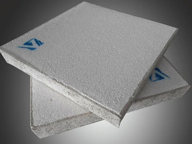
A ceramic foam filter is a three-dimensional, open-cell porous structure made from refractory ceramic material, designed to be placed in the molten metal flow path between the furnace or ladle and the casting mold. When liquid aluminium passes through the filter, non-metallic particles — oxide films, refractory fragments, intermetallic compounds, and other inclusions — are physically captured within the tortuous internal pore network and held there while clean metal continues to the mold cavity.
The structure of a ceramic foam filter looks visually similar to a natural sea sponge, but engineered with controlled pore density, interconnected void channels, and a refractory ceramic composition capable of withstanding contact with molten aluminium at temperatures up to 800°C without degradation or contamination of the metal.
We consider ceramic foam filters the single highest-impact, lowest-cost quality intervention available in aluminium casting. The filter itself may cost a few dollars per unit, but the defect reduction it enables — preventing a rejected casting worth hundreds of dollars — makes the economics overwhelming.
Why Ceramic Foam Filters Became the Industry Standard
Before ceramic foam filters gained widespread adoption in the 1970s and 1980s, aluminium foundries relied on fibreglass cloth filters, packed bed filters with loose alumina particles, or simply no filtration at all. Each earlier method had serious limitations:
- Fibreglass filters have low inclusion capture efficiency and limited thermal resistance.
- Packed bed systems are difficult to control for consistent flow and require significant infrastructure.
- No filtration produces unreliable mechanical properties and high scrap rates.
The ceramic foam filter replaced these approaches because it combines high filtration efficiency, simple installation, single-use convenience, low priming volume (the metal needed to wet the filter before flow begins), and chemical compatibility with all common aluminium alloys.
Why Inclusions in Aluminium Melt Cause Casting Failures
Understanding what inclusions are and what they do to casting properties is essential context for appreciating why filtration matters. Many procurement decisions undervalue filtration because the defect-causing role of inclusions is not fully understood.

Types of Inclusions Found in Aluminium Melt
Oxide Films (Bifilms)
Aluminium forms an oxide skin (Al₂O₃) almost instantly when the melt surface contacts air. When this oxide film folds over itself during turbulent pouring or transfer, it creates a double-layered film called a bifilm. Bifilms are the most damaging inclusion type because they act as pre-existing cracks within the solidified metal. They are typically 1–100 micrometers thick and can span millimeters in length.
Spinels (MgAl₂O₄)
In magnesium-containing alloys, magnesium reacts with aluminium oxide to form magnesium aluminate spinel particles. These hard particles are particularly difficult to remove because they tend to form stable dispersions in the melt.
Silicon Carbide and Refractory Fragments
Furnace lining erosion, ladle wear, and tooling contamination introduce hard refractory particles that cause surface defects, machining tool damage, and stress concentration points in the casting.
Intermetallic Compounds
Iron-bearing intermetallics (Al₃Fe, Al₅FeSi) precipitate during cooling when iron content exceeds the alloy’s tolerance. These plate-like particles are brittle and reduce ductility and fatigue life.
Alkali Metal Compounds
Sodium and calcium chlorides and oxides from flux treatment or raw material contamination create inclusions that can cause surface defects and reduce corrosion resistance.
How Inclusions Damage Mechanical Properties
| Inclusion Type | Primary Damage Mechanism | Typical Property Impact |
|---|---|---|
| Oxide bifilms | Pre-existing crack planes | -30 to -60% elongation reduction |
| Spinels | Hard particle stress concentrators | Fatigue life reduction |
| Refractory fragments | Machining tool damage, surface pits | Dimensional and surface defects |
| Iron intermetallics | Brittle phase in microstructure | Reduced ductility and impact strength |
| Alkali compounds | Corrosion initiation sites | Reduced corrosion resistance |
Research published in metallurgical journals consistently shows that elongation — the most inclusion-sensitive mechanical property — can drop by half or more in unfiltered aluminium compared to properly filtered metal of the same alloy and heat treatment condition. For safety-critical parts like automotive suspension components or aerospace brackets, this difference between filtered and unfiltered metal can mean the difference between a part that passes fatigue testing and one that fails prematurely.
Filtration Mechanisms: Depth Filtration vs Surface Cake Filtration
Ceramic foam filters operate through two distinct physical mechanisms, and understanding both is important for selecting the right filter grade and for interpreting filtration behavior during production.
Depth Filtration (Primary Mechanism in Early Filtration)
When metal first starts flowing through a new ceramic foam filter, the dominant mechanism is depth filtration. Inclusions are captured within the interior pore network through several sub-mechanisms:
Mechanical Straining: Particles larger than the pore throat diameter are physically blocked and cannot pass through.
Inertial Impaction: Particles with sufficient mass cannot follow the curved streamlines through the tortuous pore network and instead impact the ceramic walls.
Sedimentation: In larger pores, particles can settle onto the ceramic surface under gravity.
Surface Adhesion: The ceramic surface has a natural affinity for aluminium oxide inclusions. Once a particle contacts a pore wall, van der Waals forces and the wetting chemistry between oxide inclusion and oxide ceramic surface promote adhesion.
Cake Filtration (Progressive Buildup)
As inclusions accumulate on the filter’s upstream face, they form a layer called the filter cake. This cake itself becomes a filtration medium with even finer effective pore openings than the ceramic structure alone. Paradoxically, filtration efficiency often improves as the filter loads up — but at the cost of increasing flow resistance.
This is why ceramic foam filters are single-use items. Once a filter is saturated, the flow resistance becomes unacceptable and the risk of inclusion release increases. Re-using a spent filter introduces a major quality risk.
Priming Volume and Initial Flow
Before steady-state filtration begins, the filter must be primed — the ceramic structure must be wetted by the metal so that metal flows through rather than simply blocking at the upstream face. The priming volume is the quantity of metal required to establish flow through the filter.
Finer pore filters (higher PPI) have smaller pore openings and higher surface tension resistance, requiring more energy (metal head height) and greater priming volume. This is why very fine filters (50–60 PPI) sometimes require preheating and careful gating system design to ensure reliable priming.
Ceramic Foam Filter Material Composition and Manufacturing Process
The chemical and physical properties of the ceramic foam filter material determine its performance in aluminium applications. Not all ceramic foam filters are equal — material quality differences translate directly to filtration performance, thermal shock resistance, and contamination risk.
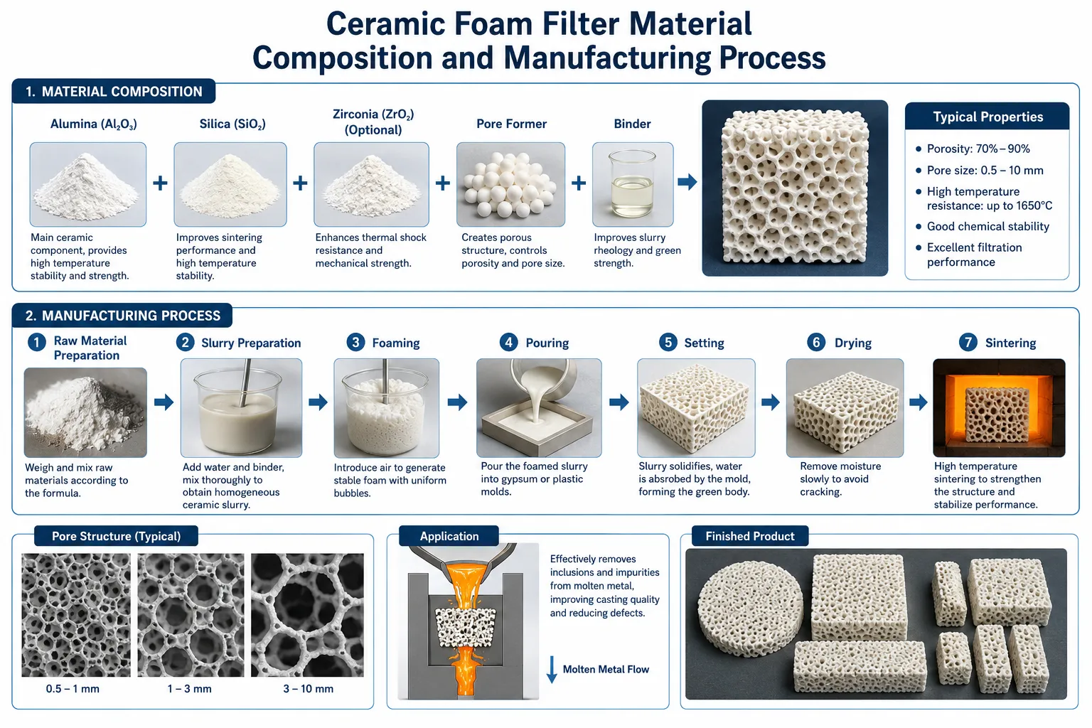
Alumina (Al₂O₃) Based Filters
Alumina ceramic foam filters are the most widely used type for aluminium filtration. The primary reasons are:
- Chemical compatibility: Al₂O₃ is thermodynamically stable in contact with molten aluminium under normal casting conditions.
- High temperature stability: Alumina maintains structural integrity above the temperature range of all aluminium casting alloys.
- Availability and cost: Alumina is one of the most commercially available refractory oxides.
Standard alumina content in quality ceramic foam filters is typically 95–99% Al₂O₃, with minor additions of silica, zirconia, or other stabilizers to improve thermal shock performance.
Zirconia (ZrO₂) Enhanced Filters
Zirconia additions to the ceramic matrix improve thermal shock resistance through the toughening mechanism associated with zirconia’s phase transformation. Some high-performance filter formulations use zirconia-mullite or partially stabilized zirconia as the primary ceramic phase. These filters are appropriate for particularly demanding conditions including very high metal flow rates, frequent thermal cycling, or contact with reactive aluminium alloys.
Silicon Carbide (SiC) Filters
Silicon carbide ceramic foam filters offer higher thermal conductivity and mechanical strength than alumina-based types. However, SiC is reactive with certain aluminium alloy compositions under specific conditions, and SiC filters are more commonly used in iron, steel, and copper alloy filtration. In aluminium applications, SiC filters are used in specific circumstances where their thermal properties justify selection.
Manufacturing Process Overview
Step 1 – Polyurethane Foam Template
Ceramic foam filter manufacturing starts with open-cell polyurethane foam cut to the required dimensions. The foam pore structure determines the final filter’s pore geometry.
Step 2 – Ceramic Slurry Coating
The polyurethane foam is immersed in a ceramic slurry containing alumina particles, colloidal silica binder, and processing additives. The slurry must be formulated to coat the foam struts uniformly without blocking the pore throats.
Step 3 – Squeeze and Blow
After impregnation, the coated foam is squeezed and blown to remove excess slurry and ensure open pore channels. This step critically determines pore uniformity.
Step 4 – Drying
The coated foam is carefully dried to remove water without cracking the green ceramic coating.
Step 5 – Firing (Burnout and Sintering)
The dried piece is fired in a kiln to first burn out the polyurethane foam template, then sinter the ceramic particles into a coherent structure. Firing temperatures typically reach 1200–1450°C.
Step 6 – Quality Inspection
Finished filters are inspected for dimensional accuracy, weight (indicating ceramic loading), visual defects, and in quality-conscious manufacturing, for pore structure and compression strength.
Quality Indicators for Ceramic Foam Filter Procurement
| Quality Parameter | Acceptable Range | Testing Method |
|---|---|---|
| Al₂O₃ content | ≥ 95% | XRF analysis |
| Compression strength | ≥ 0.6 MPa (room temp) | Compression test |
| Dimensional tolerance | ±2 mm | Caliper measurement |
| Weight uniformity | ±5% within batch | Weighing |
| Maximum service temperature | ≥ 800°C | Manufacturer certification |
| Thermal shock resistance | No cracking after rapid cooling | Thermal cycling test |
Pore Size (PPI Rating) Selection: Matching Filter Grade to Application
The PPI (pores per inch) rating is the primary specification parameter for ceramic foam filters. It indicates the number of pores counted along a one-inch linear dimension. Higher PPI means finer pores, smaller minimum particle capture size, higher filtration efficiency, and higher flow resistance.

Selecting the correct PPI for a given application is one of the most consequential decisions in filter specification. Too coarse a filter misses critical inclusions; too fine a filter creates excessive flow resistance, slows fill rates, risks cold shuts, and may not prime reliably.
Also read: How to Choose the Right PPI for Aluminum Foundry Filtration
PPI Ratings and Their Characteristics
| PPI Rating | Pore Size Range (mm) | Filtration Efficiency | Typical Application |
|---|---|---|---|
| 10 PPI | 3.0–4.0 mm | Low (coarse straining) | Pre-filter, scrap remelting |
| 20 PPI | 1.5–2.5 mm | Moderate | General gravity casting |
| 30 PPI | 1.0–1.8 mm | Good | Structural aluminium castings |
| 40 PPI | 0.6–1.2 mm | High | Automotive structural parts |
| 50 PPI | 0.4–0.8 mm | Very high | Aerospace, safety-critical |
| 60 PPI | 0.3–0.6 mm | Maximum | Premium aerospace, electronics |
Selection Criteria Beyond PPI
Metal Head Pressure: Available head (the height of metal above the filter) must be sufficient to prime the filter and maintain flow. Fine filters (50–60 PPI) require higher head. If the gating system cannot provide adequate head, a coarser filter will produce more reliable results than a fine filter that intermittently blocks.
Flow Rate Requirement: The casting fill time is determined by part weight, wall section, and alloy characteristics. The filter must allow adequate metal flow to fill the mold before premature solidification. Filter flow capacity scales with filter area — larger filter cross-sections handle higher flow rates.
Inclusion Type and Size: If the primary contamination concern is oxide bifilms (thin and flexible, often larger than 100 micrometers), even 30 PPI filters are reasonably effective. For fine intermetallic particles or fine spinel inclusions in the 10–50 micrometer range, 50–60 PPI is necessary.
Alloy Composition: High-magnesium alloys with spinel inclusions benefit from finer filtration. Silicon casting alloys with heavier oxide skins can often be adequately treated with 30–40 PPI.
Practical PPI Selection Guidelines
| Casting Type | Recommended PPI | Notes |
|---|---|---|
| HPDC (High-Pressure Die Casting) | Filtration not typical | Pressure injection bypasses filter |
| Gravity Permanent Mold | 30–40 PPI | Balance efficiency and flow |
| Sand Casting (structural) | 30–40 PPI | Larger gating systems handle flow |
| Sand Casting (automotive safety) | 40–50 PPI | Stricter quality demands |
| Investment Casting | 50–60 PPI | Very fine channels require clean metal |
| Continuous Casting (billet/slab) | 30–40 PPI inline | High throughput, continuous treatment |
| Aerospace casting | 50–60 PPI | Maximum inclusion removal |
Standard Sizes, Shapes, and Dimensional Specifications
Ceramic foam filters are manufactured in standardized dimensions to fit common filter box designs used across the industry. Understanding available sizes helps engineers design filter boxes correctly and helps procurement teams specify without ambiguity.
Common Square Filter Dimensions
| Size (mm) | Size (inches) | Typical Thickness (mm) | Typical Application |
|---|---|---|---|
| 40 × 40 | 1.5″ × 1.5″ | 22 | Small castings, jewelry |
| 50 × 50 | 2″ × 2″ | 22 | Light castings |
| 75 × 75 | 3″ × 3″ | 22 | Medium gravity castings |
| 100 × 100 | 4″ × 4″ | 22 | Standard structural castings |
| 150 × 150 | 6″ × 6″ | 25 | Large structural parts |
| 200 × 200 | 8″ × 8″ | 25–30 | Large castings, billets |
| 230 × 230 | 9″ × 9″ | 30–40 | Continuous casting |
| 300 × 300 | 12″ × 12″ | 40–50 | High-volume continuous casting |
| 381 × 381 | 15″ × 15″ | 50 | Slab casting |
Round Filter Options
Round ceramic foam filters are used in applications where circular filter boxes are preferred, particularly in certain launder systems and specialized pouring arrangements. Common diameters range from 40 mm to 300 mm with thicknesses matching the square equivalents.
Customization Capability
Beyond standard dimensions, AdTech manufactures ceramic foam filters in custom sizes, tapered profiles, stepped geometries, and with specific sealing gasket configurations. Custom filters are appropriate when standard sizes do not match existing filter box designs or when specific flow characteristics are required.
How to Install Ceramic Foam Filters Correctly in a Filter Box
Correct installation is as important as correct filter selection. A well-specified filter installed incorrectly provides little or no benefit — and can introduce its own quality problems.

Filter Box Design Requirements
The filter box (also called a filter seat or pouring basin filter seat) must:
- Support the filter on all four edges with a flat, even seating surface.
- Create a watertight (metal-tight) seal between the filter edge and the box to prevent metal bypass around the filter.
- Provide sufficient head height above the filter to prime it and maintain flow.
- Be large enough in cross-section to avoid excessive velocity above and below the filter.
- Be preheated before casting to prevent thermal shock to the filter and temperature loss in the metal.
Seating and Sealing
The most critical installation detail is sealing the filter perimeter. If molten metal finds a path around the filter edge — between the filter and the filter box wall — unfiltered metal reaches the mold cavity. The entire filtration benefit is lost.
Sealing methods include:
Refractory Fiber Gasket: A ceramic fiber rope or gasket placed in the filter box seat before the filter is placed. The filter compresses the gasket on installation, creating a seal. This is the most reliable method.
Ceramic Paste/Mortar Seal: Refractory mortar applied to the filter box seat before filter placement. Adequate when applied correctly but more variable than a fiber gasket.
Precise Dimensional Fit: If the filter box and filter dimensions are precisely matched (close tolerance), the fit itself provides adequate sealing. Less reliable than active sealing but used in some continuous casting launders.
Preheating Requirements
Cold ceramic foam filters inserted into hot aluminium metal suffer thermal shock. While quality ceramic foam filters are designed to resist thermal shock, rapid heating from room temperature to 750°C does create stress. More practically, a cold filter significantly chills the metal in contact with it, potentially causing premature freeze-off before the mold fills.
Standard practice is to preheat the filter and filter box with a torch or preheating station to at least 200–300°C before metal contact. In high-volume operations with tight cycle times, filter boxes are maintained at casting temperature between cycles.
Step-by-Step Installation Procedure
- Inspect the filter for cracks, chips, or visible damage — discard any damaged filters.
- Verify filter PPI, size, and orientation match the specification.
- Clean the filter box seating surfaces of any residue from previous castings.
- Place the sealing gasket or apply mortar to the filter seat.
- Position the filter carefully with even support on all edges.
- Preheat the filter box assembly before metal contact.
- Verify metal head height in the basin meets the minimum required for filter priming.
- After casting, do not reuse the filter — remove and dispose of the spent filter before the next heat.
Performance Testing and Inclusion Measurement Methods
Verifying that filtration is working — and quantifying improvement — requires appropriate measurement techniques. Foundries that cannot measure inclusion levels cannot optimize their filtration process.
K-Mold Test (PoDFA Precursor)
The K-Mold test samples a defined volume of metal through a standard mold geometry. The solidified sample is cross-sectioned and metallographically examined. Inclusions visible in the cross-section are counted and characterized. While relatively simple, K-Mold results are semi-quantitative and observer-dependent.
PoDFA (Porous Disk Filtration Analysis)
PoDFA is the most widely used quantitative inclusion measurement method in the aluminium industry. A defined volume of melt (typically 1–3 kg) is forced under vacuum through a fine ceramic filter disk. All inclusions larger than the disk pore size are concentrated on the disk surface. After solidification and metallographic preparation, the inclusion layer is quantified in mm²/kg — an inclusion rating that directly compares filtered vs unfiltered metal.
PoDFA can identify inclusion types (oxides, spinels, carbides) through EDX analysis of the filter residue, giving detailed information about contamination sources.
LiMCA (Liquid Metal Cleanliness Analyzer)
LiMCA uses an electrical resistance measurement principle. A small orifice is immersed in the melt, and metal is drawn through it. Inclusion particles passing through the orifice displace metal and cause a momentary increase in electrical resistance. This signal counts and sizes inclusions in real time, giving continuous cleanliness data during casting.
LiMCA is particularly valuable for continuous casting operations where real-time monitoring allows immediate response to cleanliness deterioration.
Ultrasonic Testing of Cast Samples
After solidification, ultrasonic testing of test bars or representative sections detects internal defects including inclusion clusters and porosity. This method does not identify the inclusion type but quantifies the spatial distribution of internal discontinuities.
Comparison of Inclusion Measurement Methods
| Method | Measurement Type | Speed | Quantitative | Application |
|---|---|---|---|---|
| K-Mold | Visual/semi-quantitative | Fast | No | Foundry monitoring |
| PoDFA | Quantitative (mm²/kg) | 30–60 min | Yes | R&D, qualification |
| LiMCA | Real-time particle count | Continuous | Yes | Continuous casting |
| Ultrasonic | Internal defect mapping | Variable | Partial | Post-cast QC |
| Metallographic | Visual, detailed | Hours | Yes | Root cause analysis |
Ceramic Foam Filter vs Other Filtration Methods
Multiple filtration technologies exist for aluminium, and ceramic foam filters are not the only option. Understanding the alternatives helps engineers select the right approach or combination of approaches.
Fibreglass Cloth Filters
The earliest widely adopted filter type, fibreglass cloth is woven from glass fibers into a mesh with defined aperture size. Installation is simple — the cloth is placed in the gating system. However, filtration efficiency is much lower than ceramic foam because the cloth provides only surface straining without depth filtration. Fibreglass is also temperature-limited and can contribute glass fibers as a contamination source if degraded.
Packed Bed Filters (Tabular Alumina)
Loose tabular alumina balls or chips packed in a filter box provide a deep-bed filtration medium with high inclusion capacity. Packed beds are effective but require substantial infrastructure, are not single-use in the same sense (the bed can be cleaned and reused), and provide less consistent flow compared to ceramic foam. They are most common in large-scale continuous casting operations where the filter volume and replacement logistics make ceramic foam impractical.
Ceramic Tube Filters
Porous ceramic tubes through which metal flows radially have high filtration efficiency but are primarily used in specialized applications rather than general casting. They are difficult to install in standard gating systems.
Electromagnetic Filtration
Electromagnetic stirring and filtering exploits the electrical conductivity of liquid aluminium to move the metal away from inclusions using magnetic force. This technology is highly effective for fine inclusion removal and operates continuously without physical filter replacement. The trade-off is high capital cost and complexity, limiting application to large continuous casting installations.
Comparison Table
| Filter Type | Filtration Efficiency | Capital Cost | Operating Cost | Ease of Use |
|---|---|---|---|---|
| Ceramic Foam | High | Low | Low (single use) | High |
| Fibreglass Cloth | Low-Moderate | Very low | Very low | Very high |
| Packed Bed (alumina) | High | Medium | Low (reusable) | Medium |
| Electromagnetic | Very high | Very high | Medium | Low (specialized) |
| Ceramic Tube | High | Medium | Medium | Low |
For the vast majority of aluminium casting applications — gravity casting, low-pressure casting, and semi-continuous casting — ceramic foam filters represent the optimal combination of cost, performance, and operational simplicity.
Quality Standards and Certifications That Matter
When purchasing ceramic foam filters for industrial aluminium casting, understanding applicable quality standards helps procurement teams specify filters correctly and evaluate supplier quality systems.
Industry Standards Referencing Ceramic Foam Filtration
ASTM Standards: While there is no single ASTM standard specifically for ceramic foam filters, ASTM B594 (Ultrasonic Inspection of Aluminum Alloy Wrought Products) indirectly specifies cleanliness requirements that are achieved through filtration.
AMS (Aerospace Material Specifications): Various AMS specifications for aluminium alloy castings and wrought products include cleanliness requirements that necessitate filtration. AMS 2175 covers casting classifications, and many aerospace customers specify filtration as a process requirement.
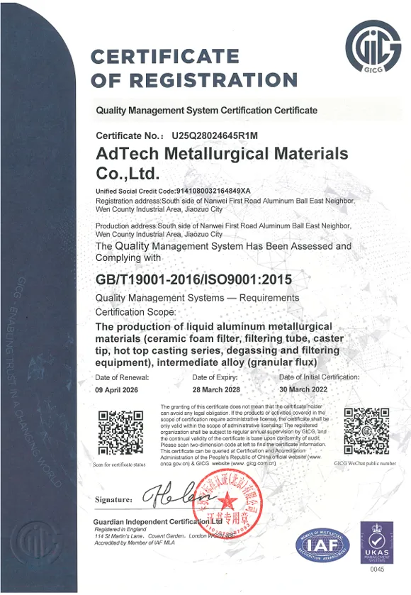
ISO 9001 / IATF 16949: Ceramic foam filter manufacturers supplying automotive foundries should hold IATF 16949 certification demonstrating a documented quality management system with process controls, dimensional inspection, and corrective action processes.
Customer-Specific Standards: Major automotive OEMs (Ford, GM, BMW, Toyota) and aerospace primes (Boeing, Airbus) typically maintain their own supplier qualification standards that ceramic foam filter manufacturers and foundries must meet.
What to Verify When Qualifying a Filter Supplier
- Material composition (XRF testing of Al₂O₃ content).
- Dimensional consistency across a batch (measure multiple filters).
- Compression strength (the filter must not fracture during installation or use).
- Batch-to-batch weight consistency (indicates consistent ceramic loading).
- Thermal shock testing results.
- References from existing customers in comparable applications.
- Production quality control documentation.
Shelf Life, Storage, and Handling Requirements
Ceramic foam filters are moisture-sensitive. Alumina is hygroscopic to a limited degree, and any absorbed moisture will be released as steam when the filter contacts hot metal. This steam can dissolve in the aluminium as hydrogen, introducing exactly the contamination the filter is meant to eliminate.
Storage Requirements
- Store filters in a dry environment with relative humidity below 60%.
- Protect from direct contact with water or condensation.
- Keep in original packaging until ready to use.
- Do not stack filters without protective packaging between them — the ceramic structure, while strong in compression, is brittle under point loads and can chip or crack.
- Store away from floors in a warehouse environment to avoid moisture from concrete.
Shelf Life
Properly stored ceramic foam filters do not have a strict expiration date — the ceramic material itself does not degrade chemically during storage. However, filters stored in humid conditions or contaminated environments should be inspected and, if in doubt, dried in an oven at 200–300°C before use. Filters showing visible moisture, contamination, or physical damage should be rejected.
Handling During Production
- Handle filters by their edges or using foam-padded tools — avoid point contact at the center of the filter face.
- Do not drop filters — even minor cracks compromise the seal and filtration integrity.
- Inspect every filter immediately before installation.
- Discard any filter with visible cracks, chips along the sealing edge, or broken struts.
Common Application Failures and How to Avoid Them
After years of supporting foundry operations, we have documented the recurring reasons why ceramic foam filtration sometimes fails to deliver expected results. Almost all failures are avoidable with proper process discipline.
Metal Bypass Around the Filter
What happens: Metal flows around the filter edge rather than through it, reaching the mold unfiltered.
Cause: Inadequate sealing between filter and filter box, oversized filter relative to box, or damaged filter edge.
Solution: Use ceramic fiber gaskets consistently. Check dimensional compatibility between filter and box. Inspect filter edges before installation.
Filter Fails to Prime
What happens: Metal does not flow through the filter, causing incomplete mold fill or excessive back-pressure.
Cause: Insufficient metal head height, very fine PPI requiring more head than available, cold filter increasing surface tension, or excessive metal viscosity (too low temperature).
Solution: Verify head height against filter flow requirements. Preheat filter adequately. Consider one PPI grade coarser if priming is chronically problematic.
Filter Fracture During Casting
What happens: The filter breaks apart during metal contact, releasing ceramic fragments into the casting.
Cause: Thermal shock from cold filter, excessive metal velocity creating pressure spike, or low-quality filter with inadequate strength.
Solution: Preheat filters before metal contact. Check metal velocity — add filter area or redesign gating to reduce velocity. Source filters from suppliers with documented compression strength testing.
Re-Contamination After Filtration
What happens: Castings show inclusions even though filtration was performed correctly.
Cause: Re-oxidation of metal between filter and mold cavity, turbulent metal flow after the filter, or oxide skins formed in the mold cavity during fill.
Solution: Minimize metal drop height after the filter. Design gating for smooth, non-turbulent fill. Review metal temperature and pouring speed.
Premature Filter Saturation
What happens: Filter loads up quickly and flow stops before the casting is complete.
Cause: Very high initial inclusion content in the melt, undersized filter for the casting, or very fine PPI filter used with heavily contaminated metal.
Solution: Address upstream contamination through degassing and melt treatment before relying solely on filtration. Use a larger filter area or two-stage filtration (coarse + fine).
Ceramic Foam Filters in Specific Aluminium Alloy Systems
A356 / A357 (Al-Si-Mg Casting Alloys)
These are the most commonly filtered aluminium casting alloys, used extensively in automotive structural applications. The primary inclusions of concern are oxide films and MgO/spinel particles from the magnesium content. We typically recommend 30–40 PPI for standard structural applications and 40–50 PPI for safety-critical parts like control arms and steering knuckles.
6061 / 6082 (Wrought Alloys via Continuous Casting)
Continuous casting of billet and slab from 6xxx series alloys uses inline ceramic foam filters in the launder system. The filter captures oxide films and spinel inclusions before the metal enters the caster, preventing surface defects and internal discontinuities in the wrought product. 30–40 PPI is standard for billet casting.
7xxx Series (Al-Zn-Mg High-Strength Alloys)
Aerospace aluminium alloys demand maximum cleanliness. Higher magnesium and zinc content increases the variety and quantity of potential inclusions. These alloys benefit most from the finest available filtration (50–60 PPI) combined with upstream degassing and, for the most critical applications, LiMCA or PoDFA verification of cleanliness.
Secondary / Recycled Aluminium
Recycled aluminium alloys inherently carry higher inclusion loads than primary metal — oxide films accumulated during remelting, intermetallics from mixed scrap compositions, and contamination from coatings or lubricants on scrap. Filtration of secondary alloys requires more careful attention to filter capacity (use larger filters or accept more frequent replacement) and upstream melt treatment to reduce inclusion load before filtration.
FAQs About Ceramic Foam Filters for Aluminium
1: Can ceramic foam filters be reused for multiple castings?
No. Ceramic foam filters are single-use items and should never be reused. After one casting, the filter has captured inclusions throughout its pore network. Reusing the filter risks releasing captured inclusions back into the metal stream as the melt’s chemistry, temperature, or flow dynamics change. Additionally, the filter may have suffered microcracking from thermal cycling that is not visible externally but compromises its structural integrity. The cost of a new filter is negligible compared to the cost of a rejected casting caused by a reused filter releasing inclusions.
2: What is the correct metal head height above a ceramic foam filter?
Minimum metal head requirements depend on filter PPI and temperature. General guidelines are: 20–30 PPI filters require approximately 75–100 mm of head; 30–40 PPI filters typically need 100–150 mm; 50–60 PPI filters may require 150–200 mm or more. These are starting points — actual requirements depend on filter area, metal temperature, and alloy composition. If the casting design cannot accommodate adequate head, a coarser filter grade should be selected.
3: How do I know if my ceramic foam filter is working?
The most practical confirmation methods are: (1) PoDFA analysis comparing inclusion levels in filtered vs unfiltered metal — a well-functioning filter reduces inclusion count by 50–90%; (2) K-Mold or density testing of cast samples; (3) Radiographic inspection of castings showing reduced or eliminated porosity; (4) Mechanical test results, particularly elongation values, which are highly sensitive to inclusion content. If casting quality improves measurably after implementing filtration, the filter is working. If quality does not improve, investigate bypass flow, incorrect PPI selection, or upstream re-contamination.
4: What causes a ceramic foam filter to turn dark or black after casting?
The black or dark coloration after casting is carbon deposition from organic residues on the scrap metal that burned during melting, or from certain flux compounds. It can also reflect the absorption of metal oxides and other dark-colored inclusions. Some darkening is normal and does not indicate a problem with the filter or the casting. If the coloration is accompanied by unusual dross formation or casting defects, investigate the scrap preparation and melt treatment process.
5: Is there a difference between Chinese-manufactured and European-manufactured ceramic foam filters?
Manufacturing location alone is not a reliable quality indicator — quality varies by individual manufacturer regardless of geography. The factors that matter are: raw material purity (Al₂O₃ content), manufacturing process control, dimensional consistency, compression strength, and quality management system. AdTech manufactures ceramic foam filters with rigorous process control and material verification. When evaluating any supplier, request material test reports, dimensional inspection records, and references from current customers. Third-party testing of sample filters before volume commitment is a sound procurement practice.
6: What size ceramic foam filter do I need for my casting?
Filter sizing depends on two main factors: the required metal flow rate and the available head height. The filter must provide enough open area to pass the required metal volume within the casting fill time without exceeding a flow velocity that would cause inclusions to push through rather than be captured. A practical starting point: for castings up to 10 kg, a 100×100 mm filter is typically adequate; for 10–50 kg castings, 150×150 mm; for 50–200 kg castings, 200×200 mm or larger. For continuous casting, filter area is calculated based on metal throughput rate and maximum acceptable pressure drop.
7: Can ceramic foam filters remove dissolved hydrogen from aluminium?
No. Ceramic foam filters capture solid and semi-solid inclusions (oxide films, particles) but have no mechanism for removing dissolved hydrogen. Hydrogen removal requires degassing — rotary impeller degassing, gas purging, or vacuum treatment. In production practice, degassing should be performed before filtration because the degassing process can generate inclusions (from melt turbulence and flux reaction) that the subsequent filter then removes. The correct sequence is: melt preparation → degassing → filtration → casting.
8: What happens if the metal temperature is too low when filtering?
Low metal temperature increases viscosity and surface tension, making it more difficult for metal to prime and flow through the filter. Below approximately 700°C for most aluminium casting alloys, priming difficulty increases significantly. Additionally, low-temperature metal is more likely to solidify within the filter pores if flow stalls, causing premature blockage. Maintain metal temperature within the alloy’s normal casting temperature range (typically 720–780°C) and ensure the filter box is preheated to avoid excessive chilling at the filter surface.
9: Do I need filtration if I am already degassing my aluminium?
Yes — degassing and filtration address different contaminant types and are complementary, not interchangeable. Degassing removes dissolved hydrogen gas. It does not effectively remove solid inclusions like oxide films, intermetallics, or refractory particles. In fact, the turbulence created by rotary degassing can generate new oxide inclusions that then need to be removed by filtration. Best practice is always to perform degassing first, then filter the degassed metal before casting.
10: How should I dispose of used ceramic foam filters?
Spent ceramic foam filters are generally classified as non-hazardous solid waste because alumina ceramic is chemically inert. However, the retained metal and any flux residues require consideration. Most foundries allow spent filters to cool, then recover the retained metal by crushing and remelting the filter in a dedicated process (noting that filter ceramic fragments in the melt would need controlled handling). The ceramic residue after metal recovery is typically sent to landfill as inert industrial waste. Check local environmental regulations — requirements vary by jurisdiction. Filters that have contacted chlorine-based fluxes may require specific disposal handling.
Summary: Key Takeaways for Engineers and Buyers
Ceramic foam filters for aluminium represent one of the most cost-effective quality investments in metal casting. The core points to retain from this technical overview are:
- Inclusion removal through ceramic foam filtration consistently improves mechanical properties, with elongation gains of 30–100% in filtered vs unfiltered metal being routinely demonstrated.
- PPI selection must balance filtration efficiency against flow requirements — 30–40 PPI covers most structural casting applications, while aerospace demands 50–60 PPI.
- Alumina-based filters are standard for aluminium compatibility, with correct Al₂O₃ content (≥95%) being a non-negotiable quality parameter.
- Proper installation with adequate sealing is as important as filter selection — bypassed metal defeats the entire filtration purpose.
- Filtration follows degassing in the correct process sequence — never substitute one for the other.
- Single-use discipline is non-negotiable — filter reuse introduces quality risk far exceeding the cost of a new filter.
- Measurement validates performance — PoDFA, LiMCA, or at minimum K-Mold testing should be used to verify that filtration is delivering the expected cleanliness improvement.
At AdTech, we manufacture ceramic foam filters across all standard PPI grades and sizes, with custom options for specialized applications. Our filters are produced with verified Al₂O₃ content, controlled dimensional tolerances, and documented quality management processes serving automotive, aerospace, and industrial aluminium casting customers worldwide.
