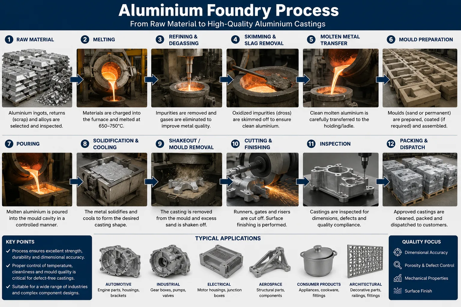
The aluminium foundry process converts raw aluminium and aluminium alloys into precisely shaped components through controlled melting, melt treatment, and casting — and when executed correctly, it produces parts that combine low density, high strength-to-weight ratio, corrosion resistance, and dimensional accuracy that few other manufacturing routes can match. After working directly with foundries across automotive, aerospace, construction, and consumer electronics supply chains, we can state with confidence that the difference between a profitable aluminium casting operation and a struggling one almost always comes down to process discipline across four stages: alloy preparation, melt quality control, casting method selection, and post-casting treatment.
If your project requires the use of Aluminum Melting De-gassing and Filtration System, you can contact us for a free quote.
Aluminium Alloy Systems Used in Foundry Operations
Which Aluminium Alloys Are Most Commonly Cast?
Not every aluminium alloy is suitable for foundry use. The casting behaviour of an alloy depends on its fluidity, solidification range, hot tearing tendency, shrinkage characteristics, and response to melt treatment. The alloy families most frequently processed in foundries fall into two broad categories: wrought alloys processed through continuous or direct chill casting, and casting alloys poured into shaped moulds.
Casting alloys are specifically formulated for good fluidity, low shrinkage, and resistance to hot cracking. Silicon is the dominant alloying element in most commercial casting alloys because it dramatically improves fluidity at lower silicon levels (around 5-7%) and provides near-eutectic flow characteristics at higher levels (10-13%). The most widely used casting alloys globally include:
| Alloy Designation | Key Alloying Elements | Typical Si Content (%) | Primary Applications |
|---|---|---|---|
| A356 / AlSi7Mg0.3 | Si, Mg | 6.5 – 7.5 | Automotive wheels, structural brackets |
| A380 / AlSi8Cu3Fe | Si, Cu, Fe | 7.5 – 9.5 | Die cast housings, covers |
| A413 / AlSi12 | Si | 11.0 – 13.0 | Marine fittings, intricate thin walls |
| A319 / AlSi6Cu3.5 | Si, Cu | 5.5 – 6.5 | Engine blocks, cylinder heads |
| A390 / AlSi17Cu4Mg | Si, Cu, Mg | 16.0 – 18.0 | Automotive compressors, wear surfaces |
| 535 / AlMg6.2 | Mg | < 0.15 | Marine hardware, corrosion-critical parts |
| A201 / AlCu4.5TiAg | Cu, Ti, Ag | < 0.10 | Aerospace high-strength castings |
Wrought alloys processed through foundry continuous casting include 1xxx, 3xxx, 5xxx, 6xxx, and 7xxx series, which are cast into billets, slabs, or wire rod for subsequent rolling, extrusion, or forging. These alloys have tighter compositional tolerances and stricter hydrogen content requirements than shaped casting alloys.
Understanding Aluminium Alloy Temper Designations
Alloy temper affects mechanical properties significantly and is often specified on engineering drawings alongside the alloy designation. For casting alloys, the common tempers are:
| Temper Code | Description | Typical Application |
|---|---|---|
| F | As-cast, no thermal treatment | Non-structural components |
| T4 | Solution heat treated, naturally aged | Moderate strength, good ductility |
| T5 | Artificially aged only (from casting) | Improved hardness without full solution treatment |
| T6 | Solution heat treated + artificially aged | Maximum strength — aerospace, automotive structural |
| T7 | Solution treated + over-aged (stabilised) | Dimensional stability under thermal cycling |
A356-T6 is arguably the most widely specified casting alloy-temper combination in automotive structural applications, delivering tensile strengths of 280-310 MPa with elongations of 8-12%.
Melting Furnace Types and Their Operational Characteristics
What Types of Furnaces Are Used in Aluminium Foundries?
Furnace selection has a direct and measurable impact on melt quality, energy consumption, metal recovery, and production throughput. We have worked with operations running all major furnace configurations, and the choice between them involves tradeoffs that are rarely captured in simple specifications.
Reverberatory Furnaces
The reverberatory furnace is the workhorse of high-volume aluminium melting. Combustion gases from burners mounted above the charge heat the melt indirectly through radiation from the furnace roof and walls, hence the name. Capacities range from 10 to over 100 tonnes of liquid aluminium.
Key characteristics:
- High throughput capability, suitable for continuous supply to downstream casting operations.
- Relatively high metal loss (2-5%) due to large surface area exposure to oxidising atmosphere.
- Lower energy efficiency per tonne compared to shaft or stack furnaces when loaded below capacity.
- Well suited to processing clean, pre-sorted scrap and primary ingot.
Crucible Furnaces
Electric resistance or gas-fired crucible furnaces heat the aluminium indirectly through a crucible (graphite-clay, silicon carbide, or steel). Capacities are smaller — typically 50kg to 2,000kg — making them ideal for job shops, alloy development, and small casting operations.
Crucible furnaces offer excellent temperature control and minimal contamination risk since the melt contacts only the crucible material. The tradeoff is higher energy cost per tonne and limited throughput.
Shaft (Stack) Furnaces
Shaft furnaces use hot combustion gases from a main chamber to pre-heat solid charge materials as they descend through a vertical shaft before entering the main melting zone. This heat recovery reduces energy consumption by 20-40% compared to a conventional reverberatory furnace. They are particularly efficient when processing clean, heavy scrap (clean sheet, extrusion scrap, machining chips after centrifuging).
Induction Furnaces
Channel induction furnaces and coreless induction furnaces use electromagnetic induction to heat the metal directly. Key advantages include:
- Very precise temperature control (±5°C achievable).
- Electromagnetic stirring promotes temperature and composition homogeneity.
- Lower metal loss than combustion furnaces due to absence of oxidising flame.
- No combustion products mean cleaner atmosphere over the melt.
The main limitation is higher capital cost and sensitivity to charge composition — high levels of oxides in the charge can cause operational problems in channel furnaces.
Furnace comparison summary:
| Furnace Type | Capacity Range | Energy Efficiency | Metal Loss | Best Application |
|---|---|---|---|---|
| Reverberatory | 10 – 100+ tonnes | Moderate | 2 – 5% | High-volume continuous production |
| Crucible (gas) | 50 kg – 2 tonnes | Low to moderate | 1 – 2% | Small batch, alloy flexibility |
| Shaft furnace | 5 – 50 tonnes | High | 1 – 3% | Clean scrap processing |
| Coreless induction | 1 – 20 tonnes | High | 0.5 – 1.5% | Precision alloys, low contamination |
| Channel induction | 5 – 60 tonnes | Very high | 0.5 – 1% | Holding and temperature homogenisation |
| Rotary furnace | 5 – 30 tonnes | Moderate | 3 – 8% | Contaminated scrap, dross recycling |
Melt Quality Control: Degassing, Fluxing, and Filtration
Why Is Melt Treatment Critical Before Casting?
Liquid aluminium is reactive. It absorbs hydrogen from atmospheric moisture, forms oxide films on its surface, and accumulates non-metallic inclusions from refractory erosion, charge contamination, and oxidation products. If these impurities are not removed before casting, they become permanently trapped in the solidified part, causing:
- Porosity (hydrogen gas evolution during solidification)
- Oxide inclusions (reduced tensile strength, fatigue resistance)
- Hard particle inclusions (machining tool damage, surface defects)
- Shrinkage porosity (inadequate feeding due to oxide films blocking flow)
The three pillars of melt quality control are degassing, fluxing, and filtration — and in a well-run foundry, all three are applied in the correct sequence.
Rotary Degassing: The Standard for Hydrogen Removal
Rotary degassing uses a spinning graphite rotor submerged in the melt to break a stream of argon (or nitrogen) into fine bubbles. These bubbles provide the interfacial surface area needed for dissolved hydrogen to transfer from the melt into the gas phase, where it is carried away as the bubble rises and exits the melt surface.
Critical operating parameters:
- Rotor tip speed: 3.5 – 6.5 m/s (optimal bubble generation range).
- Argon flow rate: 0.5 – 2.0 L/min per tonne of melt.
- Treatment temperature: 720 – 760°C.
- Treatment duration: Based on initial hydrogen measurement, typically 10-25 minutes.
The target hydrogen content varies by application, from below 0.10 mL/100g Al for aerospace to below 0.20 mL/100g Al for general castings.
Fluxing Operations in Aluminium Foundries
Fluxing serves several distinct functions depending on the flux type selected:
Cover fluxes protect the melt surface from oxidation by creating a molten salt barrier between the aluminium and the furnace atmosphere. They are applied as a thin layer to the melt surface and are particularly important in high-magnesium alloys where oxidation rates are elevated.
Cleaning fluxes react with and absorb oxide inclusions, gathering them into a removable dross layer. They typically contain chloride and fluoride salts that wet aluminium oxide surfaces and draw them into the flux phase.
Degassing fluxes (tablet or powder form) release reactive gases when immersed, generating bubbles that carry hydrogen from the melt. While less efficient than rotary degassing, they are used in smaller operations or as a supplement.
Grain refining fluxes introduce titanium and boron — typically as Al-5Ti-1B master alloy — to provide heterogeneous nucleation sites during solidification, producing a fine, equiaxed grain structure with improved mechanical properties.
Ceramic Foam Filtration: Removing Inclusions Before Casting
After degassing and fluxing, the treated melt still contains residual inclusions that are too small for visual detection but large enough to cause scrap in finished castings. Ceramic foam filters (CFF) installed in the launder or filtration box remove these inclusions through a combination of mechanical interception and surface adhesion as the melt flows through the filter’s tortuous pore network.
Filter grade selection by application:
| Filter Pore Grade (PPI) | Filtration Efficiency | Typical Application |
|---|---|---|
| 10 PPI | Low — large inclusions only | General sand castings, non-critical parts |
| 20 PPI | Moderate | Standard automotive castings |
| 30 PPI | Good | Structural automotive, thin-wall castings |
| 40 PPI | High | Aerospace, critical structural parts |
| 50 – 60 PPI | Very high | High-purity, thin-section precision castings |
AdTech manufactures ceramic foam filters in alumina, silicon carbide, and zirconia materials to cover the full temperature and application range for aluminium foundry operations.
Sand Casting: Process Principles, Advantages, and Limitations
How Does Sand Casting Work for Aluminium Components?
Sand casting is the oldest and most flexible aluminium casting method. A pattern representing the final part geometry is used to form a cavity in a sand mould, which is then filled with liquid aluminium. After solidification and cooling, the mould is broken apart to retrieve the casting.
The two main sand systems used in aluminium foundries are:
Green sand (silica sand bonded with bentonite clay and water) is the most economical option for high-volume production. The sand mixture is reusable and offers good permeability to allow gases generated during casting to escape. Green sand is suitable for parts with moderate complexity and dimensional tolerances of ±1.5 to ±3mm.
No-bake (chemically bonded) sand uses synthetic binders (furan, phenolic urethane, or sodium silicate) that cure at room temperature without heating. No-bake moulds are stronger than green sand, allow more complex geometries with tighter tolerances (±0.8 to ±1.5mm), and are better suited to low-volume or complex parts.
Sand casting process parameters:
| Parameter | Green Sand | No-Bake Sand |
|---|---|---|
| Dimensional tolerance | ±1.5 – 3.0 mm | ±0.8 – 1.5 mm |
| Surface finish (Ra) | 6.3 – 12.5 μm | 3.2 – 6.3 μm |
| Minimum wall thickness | 3 – 5 mm | 2.5 – 4 mm |
| Tooling cost | Low | Low to moderate |
| Suitable production volume | 1 – 10,000+ parts | 1 – 5,000 parts |
| Core complexity | Moderate | High |
Where sand casting excels:
- Large, complex components where die tooling costs cannot be justified.
- Low to medium production volumes.
- Parts requiring internal cavities (cores are easily incorporated).
- Prototype and short-run production.
Where sand casting falls short:
- High-volume production (cycle times of 15-60+ minutes per mould cannot compete with die casting).
- Thin-wall sections below 2.5mm.
- High dimensional precision requirements.
- Applications where superior surface finish is needed without secondary operations.
Die Casting: High-Pressure and Low-Pressure Methods Compared
What Is the Difference Between High-Pressure and Low-Pressure Die Casting?
Die casting encompasses two fundamentally different approaches to filling a permanent steel mould (die) with liquid aluminium, and the choice between them has significant implications for part quality, tooling investment, and production rate.
High-Pressure Die Casting (HPDC)
High-pressure die casting injects molten aluminium into a steel die at pressures ranging from 40 to 120 MPa (400 to 1,200 bar), at injection velocities of 30 to 80 m/s. The entire fill cycle — from injection to initial solidification — occurs in fractions of a second. This speed is what allows HPDC to achieve the thin walls, fine surface detail, and tight tolerances that make it the dominant casting method for high-volume automotive and consumer electronics components.
HPDC key process characteristics:
| Parameter | Typical Range |
|---|---|
| Injection pressure | 40 – 120 MPa |
| Metal injection velocity | 30 – 80 m/s |
| Cycle time | 15 – 120 seconds |
| Minimum wall thickness | 0.8 – 1.5 mm |
| Dimensional tolerance | ±0.1 – 0.3 mm |
| Surface finish (Ra) | 0.8 – 3.2 μm |
| Tooling cost | Very high ($50,000 – $500,000+) |
| Production volume threshold | 10,000 – 1,000,000+ parts |
The main limitation of HPDC is porosity from gas entrapment. The high injection velocity causes turbulent filling that traps air and combustion gases from the die lubricant inside the cavity. These gas pores are distributed through the casting cross-section and prevent heat treatment (gas pores expand and blister during solution treatment). Vacuum-assisted HPDC reduces this problem by evacuating the die cavity before injection, making T6 heat treatment of HPDC parts feasible.
Low-Pressure Die Casting (LPDC)
Low-pressure die casting uses a pressurised furnace below the die (typically 0.05 to 0.15 MPa air or inert gas pressure) to push liquid metal upward through a riser tube into the die cavity. The slow, controlled, bottom-up filling produces a laminar flow pattern that largely eliminates air entrapment.
Key advantages of LPDC:
- Superior metallurgical quality compared to HPDC (lower porosity, heat-treatable).
- Good dimensional consistency.
- High metal yield (80-90%) because the riser tube metal returns to the furnace between shots.
- Suitable for alloys requiring T6 treatment (automotive wheels, structural brackets).
Key limitations:
- Longer cycle times (60-180 seconds) compared to HPDC.
- Limited to moderately complex geometries.
- Higher furnace maintenance requirements.
HPDC vs. LPDC comparison:
| Criterion | High-Pressure Die Casting | Low-Pressure Die Casting |
|---|---|---|
| Fill pressure | 40 – 120 MPa | 0.05 – 0.15 MPa |
| Fill pattern | Turbulent | Laminar |
| Porosity level | Moderate to high | Low |
| Heat treatable | No (standard) / Yes (vacuum) | Yes |
| Cycle time | 15 – 120 sec | 60 – 180 sec |
| Minimum wall thickness | 0.8 mm | 2.0 mm |
| Tooling cost | Very high | High |
| Best applications | High-volume thin-wall parts | Structural components requiring T6 |
Permanent Mould Casting and Gravity Die Casting
What Is Gravity Die Casting and When Is It the Right Choice?
Gravity die casting (also called permanent mould casting in North American terminology) pours liquid aluminium into a metal mould under gravity alone — no external pressure. The steel or cast iron mould is reused for hundreds to thousands of cycles, making it more economical than sand casting for medium production volumes while avoiding the high tooling investment of die casting.
The controlled mould temperature and faster heat extraction compared to sand casting produce a finer grain structure and better mechanical properties than sand castings of equivalent geometry.
Typical gravity die casting properties (A356-T6):
| Property | Sand Cast A356-T6 | Gravity Die Cast A356-T6 | LPDC A356-T6 |
|---|---|---|---|
| Tensile strength (MPa) | 228 | 262 | 283 |
| Yield strength (MPa) | 165 | 186 | 207 |
| Elongation (%) | 5 | 6 | 9 |
| Hardness (HB) | 70 | 80 | 85 |
Gravity die casting is particularly well suited to:
- Medium production volumes (500 to 50,000 parts)
- Parts requiring better mechanical properties than sand casting.
- Components where pressure tightness is required (hydraulic housings, valve bodies)
- Geometries with moderate complexity.
Investment Casting and Lost Foam Casting for Complex Geometries
How Does Investment Casting Achieve Near-Net-Shape Aluminium Parts?
Investment casting (also called the lost wax process) produces aluminium components with exceptional dimensional accuracy and surface finish by pouring metal into ceramic moulds formed around expendable wax patterns. The process allows internal geometries, undercuts, and fine surface details that are impossible or extremely costly to achieve through any other method.
Investment casting process steps:
- Inject wax into a metal die to form the pattern.
- Assemble multiple patterns onto a wax sprue tree.
- Dip the assembly repeatedly into ceramic slurry, building a ceramic shell (8-12 dip coats).
- Melt out the wax in an autoclave (steam dewax).
- Fire the ceramic shell at 900-1,100°C to develop strength.
- Pour liquid aluminium into the preheated shell.
- Break away the ceramic after solidification.
- Cut individual castings from the sprue tree.
Aluminium investment casting tolerances and surface finish:
| Dimension Range | Achievable Tolerance | Surface Finish (Ra) |
|---|---|---|
| Up to 25 mm | ±0.13 mm | 1.6 – 3.2 μm |
| 25 – 150 mm | ±0.25 mm | 1.6 – 3.2 μm |
| 150 – 300 mm | ±0.50 mm | 3.2 – 6.3 μm |
Lost Foam Casting
Lost foam casting replaces the wax pattern with an expanded polystyrene (EPS) foam pattern that remains in the mould during casting. When liquid aluminium contacts the foam, the foam vaporises and is replaced by metal. The process combines many advantages of investment casting (complex geometry capability) with the simplicity of sand casting (no shell building, no dewaxing).
Lost foam is widely used for complex engine components like cylinder heads and intake manifolds where internal passages would otherwise require multiple sand cores.
Continuous Casting and Direct Chill Casting for Billet and Slab Production
What Is the Direct Chill Casting Process for Aluminium?
Direct chill (DC) casting is the primary method for producing aluminium billets (round cross-sections for extrusion) and rolling slabs (rectangular cross-sections for rolling mills). The process involves pouring liquid aluminium into a water-cooled mould that is open at the bottom. As the metal solidifies in the mould, a hydraulic ram lowers the solidified section continuously while fresh liquid metal is supplied from above.
Simultaneous direct water cooling of the solidified shell below the mould provides rapid heat extraction and fine microstructure. DC casting produces billets from 100mm to over 1,200mm diameter and slabs up to 2,000mm wide.
Critical DC casting parameters:
| Parameter | Typical Range | Effect of Deviation |
|---|---|---|
| Casting speed | 40 – 150 mm/min | Too fast: cold cracking; too slow: hot cracking |
| Cooling water flow | 100 – 300 L/min/m | Insufficient: surface cracks; excess: thermal shock |
| Metal temperature (tundish) | 680 – 720°C | Too hot: bleed-outs; too cold: cold shuts |
| Hydrogen content | < 0.12 mL/100g Al | Excess: porosity, reduced fatigue life |
The melt quality requirements for DC casting are stricter than for most shaped casting processes because the billets and slabs produced are subsequently deformed (extruded, rolled, forged) where hydrogen porosity and inclusions can cause cracking, surface defects, and rejection.
Casting Defect Prevention: Root Causes and Control Methods
What Are the Most Common Aluminium Casting Defects?
Understanding defect formation mechanisms is more valuable than memorising a list of defects. When you know why a defect forms, corrective action becomes logical rather than trial-and-error.
Gas porosity originates from dissolved hydrogen precipitating during solidification or from air entrapment during mould filling. Prevention: proper degassing (target H₂ below specification), controlled filling velocity, vented moulds.
Shrinkage porosity forms when the solidifying casting cannot draw in sufficient liquid metal to compensate for the 6-7% volumetric shrinkage of aluminium during solidification. Prevention: correct gating and riser design, proper solidification sequence (directed solidification from the furthest point to the riser).
Cold shuts and misruns occur when two metal streams meet with insufficient temperature to fuse properly, or when the metal freezes before filling the mould completely. Prevention: increase melt temperature, increase pour rate, preheat the mould.
Hot tearing (hot cracking) develops in the semi-solid state when thermal contraction stresses exceed the strength of the partially solidified metal. Prevention: use alloys with narrower solidification ranges, reduce mould restraint, adjust cooling rate.
Oxide inclusions are entrained oxide films from the melt surface or from turbulent filling. Prevention: proper fluxing and degassing, reduced turbulence during transfer and pouring, bottom-gated or side-gated filling systems, ceramic foam filtration.
Defect frequency by casting method:
| Defect Type | Sand Casting | HPDC | LPDC | Gravity Die | Investment |
|---|---|---|---|---|---|
| Gas porosity | Moderate | High | Low | Low | Very low |
| Shrinkage porosity | Moderate | Moderate | Low | Moderate | Low |
| Oxide inclusions | Moderate | Moderate | Low | Low | Very low |
| Cold shuts | Low | Low | Low | Moderate | Very low |
| Hot tearing | Low | Low | Very low | Low | Very low |
| Dimensional deviation | High | Very low | Low | Moderate | Very low |
Post-Casting Operations: Heat Treatment, Machining, and Surface Finishing
What Post-Casting Treatments Are Required for Aluminium Castings?
Most structural aluminium castings require at least one post-casting operation before they meet final specifications. Heat treatment, in particular, is often the step that transforms a mediocre casting into a high-performance component.
T6 Heat Treatment Sequence:
- Solution heat treatment: Heat to 520-540°C (alloy-dependent) for 4-12 hours to dissolve alloying elements into solid solution.
- Quench: Rapid transfer to water at 60-80°C within 15 seconds of furnace exit (prevents precipitation during cooling).
- Artificial ageing: Heat to 155-170°C for 4-16 hours to precipitate fine strengthening phases (Mg₂Si for A356).
Effect of T6 treatment on A356 mechanical properties:
| Condition | Tensile Strength (MPa) | Yield Strength (MPa) | Elongation (%) |
|---|---|---|---|
| As-cast (F) | 165 | 115 | 4 |
| T5 (aged only) | 207 | 165 | 3 |
| T6 (solution + age) | 283 | 207 | 9 |
Surface finishing options for aluminium castings:
| Process | Surface Improvement | Typical Application |
|---|---|---|
| Shot blasting | Removes scale, improves fatigue | Structural components |
| Machining | Dimensional accuracy, smooth contact faces | Mating surfaces, threaded features |
| Anodising | Corrosion and wear resistance | Exposed surfaces, decorative parts |
| Powder coating | Colour, corrosion protection | Architectural, consumer products |
| Electroplating | Enhanced surface properties | Functional decorative parts |
| Impregnation | Seals porosity for pressure tightness | Hydraulic housings, compressor parts |
Aluminium Foundry Applications by Industry Sector
Where Are Aluminium Castings Used Across Industries?
The breadth of aluminium casting applications is one of the strongest arguments for the material’s versatility. The combination of light weight, strength, corrosion resistance, and castability has made aluminium the material of choice across multiple demanding sectors.
Automotive sector is the largest single consumer of aluminium castings globally, driven by lightweighting mandates to improve fuel efficiency and extend electric vehicle range. Key automotive applications:
- Engine blocks and cylinder heads (A319, A380)
- Transmission housings (A380)
- Wheels (A356-T6, LPDC)
- Suspension components and knuckles (A356-T6)
- Battery trays and housings for electric vehicles (HPDC, structural die casting)
Aerospace sector uses aluminium investment castings and precision sand castings for structural frames, brackets, housings, and airframe components. The material must meet stringent porosity and inclusion specifications, typically requiring melt hydrogen below 0.10 mL/100g Al and X-ray or CT inspection of finished castings.
Construction and architecture relies on permanent mould and sand castings for window and curtain wall fittings, handrails, and decorative architectural elements where corrosion resistance and aesthetic quality are both requirements.
Electronics and telecommunications has grown rapidly as a market for thin-wall HPDC components — heat sinks, 5G antenna housings, server chassis components — where dimensional accuracy, thermal conductivity, and surface finish are critical.
Marine and offshore applications favour corrosion-resistant alloys (5xxx series, A356) for pump housings, impellers, and structural brackets exposed to salt water.
| Industry Sector | Dominant Casting Methods | Key Alloys | Critical Quality Parameters |
|---|---|---|---|
| Automotive powertrain | HPDC, sand, LPDC | A319, A380, A356 | Pressure tightness, dimensional accuracy |
| Automotive structural | LPDC, gravity die | A356-T6 | Mechanical strength, elongation |
| Aerospace | Investment, sand | A356, A201, 357 | Porosity < 0.10 mL/100g, X-ray clean |
| Electronics | HPDC | A380, ADC12 | Thin wall, surface finish, heat dissipation |
| Marine | Sand, gravity die | A356, 535 | Corrosion resistance, pressure tightness |
| Construction | Sand, permanent mould | 6xxx, A356 | Surface finish, anodising quality |
Equipment and Consumables Selection for Aluminium Foundries
What Equipment Does an Aluminium Foundry Need?
The capital equipment and consumables mix for an aluminium foundry depends heavily on casting method, production volume, and alloy range. However, the melt treatment equipment requirements are consistent across virtually all aluminium casting operations.
Core melt treatment equipment:
Rotary degassing units are available in portable (ladle treatment) and inline (continuous) configurations. Key selection criteria:
- Melt volume capacity (kg or tonnes per treatment cycle)
- Rotor material (isostatic graphite for longevity)
- RPM range and control precision
- Gas flow metering capability
Ceramic foam filter boxes hold the filter in position during metal transfer and maintain the correct filter preheat temperature. Filter box design affects both filtration efficiency and metal yield.
Launder systems transfer liquid metal from furnace to casting machine with minimal turbulence and temperature loss. Heated launder sections maintain metal temperature, while filter boxes are integrated inline.
Grain refining and modification stations add master alloys (Al-Ti-B for grain refinement, Al-Sr or Al-Na for silicon modification) at controlled rates and positions in the melt stream.
Hydrogen measurement instruments — in-line Telegas-type probes or portable Reduced Pressure Test equipment — provide the process control data needed to verify melt quality before casting.
AdTech supplies degassing units, ceramic foam filters (10-60 PPI), launder refractories, grain refiner alloys, and melt treatment fluxes to aluminium foundries and casting operations worldwide. Our engineering team supports equipment selection, parameter optimisation, and consumables specification for new and existing operations.
Environmental and Sustainability Considerations in Modern Aluminium Foundries
How Are Aluminium Foundries Reducing Their Environmental Impact?
Aluminium has a compelling sustainability story: it is 100% recyclable without loss of properties, and recycling requires only 5% of the energy needed to produce primary aluminium from bauxite. However, the foundry process itself generates environmental challenges that modern operations must actively manage.
Dross generation and management: Every aluminium melting operation generates dross — a mixture of aluminium metal and aluminium oxide that forms at the melt surface. Dross represents both a metal loss (1-5% of melt weight) and a waste disposal challenge. Modern rotary salt furnaces recover metal from dross at rates of 50-70%, returning the recovered aluminium to the production cycle.
Flux salt waste: Fluxing operations that use chloride-fluoride salts generate salt cake waste that requires careful disposal or recycling. Closed-loop salt recovery systems are increasingly used in large operations to minimise waste generation.
Energy efficiency: Shaft furnaces and channel induction furnaces represent the current state of the art in melting energy efficiency, achieving energy consumption below 450 kWh per tonne of aluminium melted. This compares favourably to older reverberatory designs consuming 700-900 kWh per tonne.
Emissions control: Natural gas combustion in reverberatory and crucible furnaces generates NOₓ, CO, and particulate emissions. Low-NOₓ burner technology, heat recovery systems, and electrification of melting operations are all active areas of investment in the aluminium foundry sector.
Recycled content: The use of post-consumer and post-industrial scrap aluminium is standard practice in most foundries. Maintaining alloy purity while maximising scrap use requires careful charge calculation and melt quality monitoring.
FAQs — Questions About the Aluminium Foundry Process
Q1: What is the aluminium foundry process in simple terms?
The aluminium foundry process involves melting aluminium alloys in a furnace, treating the liquid metal to remove dissolved hydrogen and non-metallic inclusions, and then pouring or injecting the treated melt into a mould shaped to produce a desired component. After solidification and cooling, the casting is removed from the mould and may undergo further operations such as heat treatment, machining, or surface finishing before it is delivered as a finished part.
Q2: What is the most common casting method for aluminium?
High-pressure die casting (HPDC) is the most widely used casting method for aluminium in terms of total production volume globally, driven primarily by automotive and electronics demand for thin-wall, high-volume components. Sand casting is the most commonly available method across the widest range of foundry sizes and is preferred for large, complex, or low-volume parts. Low-pressure die casting is the dominant method for aluminium alloy wheels.
Q3: What aluminium alloy is most often used in foundries?
A356 (AlSi7Mg0.3) is one of the most widely used casting alloys globally because it combines excellent castability, good mechanical properties in the T6 condition, and compatibility with most casting methods. A380 (AlSi8Cu3Fe) is the most common alloy for high-pressure die casting due to its outstanding fluidity and die-filling ability.
Q4: How is hydrogen removed from liquid aluminium before casting?
Hydrogen is removed through rotary degassing, where a spinning graphite rotor disperses fine argon or nitrogen bubbles throughout the melt. Dissolved hydrogen diffuses from the melt into these bubbles and is carried away as the bubbles rise and exit the melt surface. The treatment typically reduces hydrogen content from 0.3-0.5 mL/100g Al to below 0.10-0.15 mL/100g Al within 10-25 minutes, depending on process parameters.
Q5: What is the difference between a casting and a forging in aluminium?
Aluminium castings are produced by pouring or injecting liquid metal into a mould — the metal takes the shape of the cavity during solidification. Aluminium forgings are produced by mechanically deforming solid or semi-solid aluminium under high pressure using dies. Forgings generally have higher strength and better fatigue resistance than castings of equivalent geometry because the deformation process refines the grain structure and eliminates porosity. Castings can achieve more complex geometries, thinner walls, and are typically lower in cost for complex shapes.
Q6: What causes porosity in aluminium castings and how is it prevented?
Aluminium casting porosity has two distinct origins. Gas porosity (smooth, spherical pores) forms from dissolved hydrogen precipitating during solidification — prevented by proper degassing before casting. Shrinkage porosity (irregular, interconnected voids) forms when solidifying metal cannot draw in sufficient liquid to compensate for volumetric shrinkage — prevented by correct riser and gating design that ensures directional solidification toward feed points. The RPT (Reduced Pressure Test) and X-ray inspection are standard quality control methods for detecting and quantifying porosity.
Q7: What is the role of ceramic foam filters in the aluminium casting process?
Ceramic foam filters are installed in the metal transfer system between the furnace and the mould cavity. As liquid aluminium flows through the filter’s open-cell foam structure, solid inclusions (oxide films, refractory particles, intermetallic compounds) are captured by a combination of mechanical screening and surface adhesion. Filtration significantly improves melt cleanliness, reducing inclusion-related defects and improving the mechanical properties — particularly fatigue life and elongation — of the finished casting.
Q8: How long does the aluminium casting process take from melt to finished part?
The total cycle time depends entirely on the casting method and part complexity. High-pressure die castings can cycle in 15-120 seconds. Gravity die castings require 2-10 minutes per cycle. Sand castings may need 30 minutes to several hours for large parts to solidify completely. Investment castings have the longest preparation time (days to build the ceramic shell) but the actual casting step is rapid. Heat treatment adds 8-20 hours for T6 conditions. Total manufacturing lead time from order to finished machined part typically ranges from 2 days (HPDC) to several weeks (investment casting with heat treatment and machining).
Q9: What temperature is aluminium melted at in a foundry?
The melting point of pure aluminium is 660°C. In foundry practice, aluminium alloys are typically processed at temperatures of 700-780°C — above the liquidus temperature to ensure complete melting and adequate fluidity for mould filling. Higher temperatures improve fluidity but increase oxidation, hydrogen absorption, and energy consumption. The optimal processing temperature is alloy-specific and influenced by the casting method used. HPDC typically operates at 640-680°C at the shot sleeve (below melt furnace temperature due to rapid solidification design), while investment casting may use temperatures up to 780°C for complex thin-wall sections.
Q10: What quality standards apply to aluminium foundry products?
Aluminium castings are subject to multiple quality standards depending on the application sector. Widely referenced standards include ASTM B85 (aluminium alloy die castings), ASTM B108 (permanent mould castings), AMS standards for aerospace castings, NADCA standards for die casting tolerances and inspection, and OEM-specific standards from automotive manufacturers such as GM, Ford, and European OEMs. Melt quality is often governed by internal foundry specifications for hydrogen content (verified by RPT or Telegas) and inclusion level (verified by PoDFA or Prefil analysis for critical applications). X-ray and CT scanning to ASTM E505 or EN 12681 are standard inspection methods for porosity in structural castings.
Conclusion: Choosing the Right Process for Your Aluminium Casting Requirements
The aluminium foundry process is not a single method but a family of related techniques, each with a distinct combination of strengths, limitations, cost structures, and quality capabilities. The optimal process choice for any specific component follows from a systematic evaluation of:
- Annual production volume (die casting tooling is only cost-effective above certain quantities).
- Component geometry complexity and wall thickness requirements.
- Mechanical property and heat treatment requirements.
- Dimensional tolerance and surface finish specifications.
- Application environment (corrosion, pressure, fatigue loading).
- Budget constraints for tooling and unit piece price.
Summary matrix — aluminium casting method selection:
| Selection Criteria | Sand | Gravity Die | LPDC | HPDC | Investment | Lost Foam |
|---|---|---|---|---|---|---|
| Geometry complexity | High | Moderate | Moderate | Moderate | Very high | High |
| Minimum wall thickness | 3 mm | 2.5 mm | 2.0 mm | 0.8 mm | 0.5 mm | 2.5 mm |
| Dimensional accuracy | Low | Moderate | Good | Very good | Excellent | Good |
| Mechanical properties | Moderate | Good | Very good | Moderate | Good | Good |
| Heat treatable | Yes | Yes | Yes | Limited | Yes | Yes |
| Tooling cost | Low | Moderate | High | Very high | Low-moderate | Low |
| Optimal volume range | 1-5,000 | 500-50,000 | 5,000-200,000 | 50,000+ | 10-10,000 | 100-50,000 |
At AdTech, our engineering team has supported aluminium foundries and casting operations across four continents in optimising melt quality, selecting appropriate casting processes, and specifying the right filtration, degassing, and refractory products for their production requirements. We bring hands-on operational knowledge to every conversation — not just catalogue specifications.
