알루미늄 주조 공정은 원료 알루미늄과 알루미늄 합금을 정밀한 제어를 통해 용해, 용융 처리 및 주조 과정을 거쳐 정밀한 형상의 부품으로 변환하는 과정입니다. 이 공정이 올바르게 수행될 경우, 다른 제조 방식으로는 따라잡기 힘든 낮은 밀도, 높은 강도 대비 중량 비율, 내식성 및 치수 정밀도를 모두 갖춘 부품을 생산할 수 있습니다. 자동차, 항공우주, 건설 및 가전 제품 공급망 전반에 걸친 주조 업체들과 직접 협력해 온 경험을 바탕으로, 수익성 있는 알루미늄 주조 사업과 어려움을 겪는 사업 간의 차이는 거의 항상 합금 준비, 용융 품질 관리, 주조 방법 선정, 주조 후 처리라는 네 가지 단계에 걸친 공정 규율에 달려 있다고 자신 있게 말할 수 있습니다.
프로젝트에 알루미늄 용해 탈가스 및 여과 시스템이 필요한 경우, 다음을 수행할 수 있습니다. 문의하기 무료 견적을 요청하세요.
주조 공정에 사용되는 알루미늄 합금 시스템
어떤 알루미늄 합금이 주조용으로 가장 널리 사용되나요?
모든 알루미늄 합금이 주조용으로 적합한 것은 아닙니다. 합금의 주조 거동은 유동성, 응고 범위, 열간 균열 경향, 수축 특성 및 용융 처리 반응에 따라 달라집니다. 주조 공장에서 가장 빈번하게 가공되는 합금군은 크게 두 가지 범주로 나뉩니다. 즉, 연속 주조 또는 직접 냉각 주조를 통해 가공되는 가공용 합금과, 형틀에 주입되는 주조용 합금입니다.
주조 합금 이 합금들은 우수한 유동성, 낮은 수축률, 그리고 고온 균열 저항성을 갖도록 특별히 배합되었습니다. 실리콘은 대부분의 상용 주조 합금에서 주된 합금 원소로 사용되는데, 이는 낮은 실리콘 함량(약 5~7%)에서는 유동성을 획기적으로 향상시키고, 높은 함량(10~13%)에서는 유동 특성이 유동점에 근접하게 만들기 때문입니다. 전 세계적으로 가장 널리 사용되는 주조 합금은 다음과 같습니다:
| 합금 명칭 | 주요 합금 원소 | 일반적인 실리콘 함량 (%) | 주요 애플리케이션 |
|---|---|---|---|
| A356 / AlSi7Mg0.3 | Si, Mg | 6.5 – 7.5 | 자동차 휠, 구조용 브라켓 |
| A380 / AlSi8Cu3Fe | Si, Cu, Fe | 7.5 – 9.5 | 다이캐스팅 하우징, 커버 |
| A413 / AlSi12 | 네 | 11.0 – 13.0 | 선박용 피팅, 정교한 얇은 벽면 |
| A319 / AlSi6Cu3.5 | Si, Cu | 5.5 – 6.5 | 엔진 블록, 실린더 헤드 |
| A390 / AlSi17Cu4Mg | Si, Cu, Mg | 16.0 – 18.0 | 자동차용 압축기, 마모 부위 |
| 535 / AlMg6.2 | Mg | < 0.15 | 선박용 하드웨어, 부식이 중요한 부품 |
| A201 / AlCu4.5TiAg | Cu, Ti, Ag | < 0.10 | 항공우주용 고강도 주조품 |
단조 합금 주조 연속 주조 공정을 거치는 합금에는 1xxx, 3xxx, 5xxx, 6xxx 및 7xxx 계열이 포함되며, 이들은 빌렛, 슬래브 또는 선재로 주조된 후 압연, 압출 또는 단조 공정을 거칩니다. 이러한 합금은 성형 주조 합금에 비해 성분 공차가 더 엄격하고 수소 함량 요건도 더 까다롭습니다.
알루미늄 합금 템퍼 표기법 이해
합금의 경도 상태는 기계적 특성에 큰 영향을 미치며, 종종 공학 도면에서 합금 명칭과 함께 명시됩니다. 주조용 합금의 경우, 일반적인 경도 상태는 다음과 같습니다:
| 온도 코드 | 설명 | 일반적인 애플리케이션 |
|---|---|---|
| F | 주조 상태, 열처리 미실시 | 비구조적 구성 요소 |
| T4 | 열처리 및 자연 숙성 | 적당한 강도, 우수한 연성 |
| T5 | (주조 후) 인위적으로만 노화 처리됨 | 완전한 용액 처리를 거치지 않고 경도를 향상시킴 |
| T6 | 열처리 및 인위적 노화 처리 | 최고의 강도 — 항공우주, 자동차 구조용 |
| T7 | 용액 처리 및 과숙성(안정화) | 열 사이클링 하에서의 치수 안정성 |
A356-T6는 자동차 구조용 분야에서 가장 널리 사용되는 주조 합금-열처리 조합으로 꼽히며, 인장 강도 280~310 MPa와 연신율 8~12%를 제공합니다.
용해로의 종류와 그 작동 특성
알루미늄 주조 공장에서는 어떤 종류의 용광로를 사용하나요?
용광로 선정은 용융 품질, 에너지 소비, 금속 회수율 및 생산 처리량에 직접적이고 가시적인 영향을 미칩니다. 당사는 모든 주요 용광로 구성을 운영하는 사업장들과 협력해 왔으며, 이들 사이에서 선택을 내릴 때는 단순한 사양만으로는 파악하기 어려운 여러 가지 장단점이 존재합니다.
반사로
반사로(reverberatory furnace)는 대량 알루미늄 용해의 주력 설비입니다. 원료 적재부 상단에 설치된 버너에서 배출되는 연소 가스는 용광로 지붕과 벽면을 통해 복사열로 용융물을 간접 가열하며, 이 원리에서 설비의 이름이 유래되었습니다. 용량은 액상 알루미늄 10톤에서 100톤 이상에 이릅니다.
주요 특징:
- 높은 처리 능력을 갖추고 있어, 후속 주조 공정에 지속적으로 공급하기에 적합합니다.
- 산화성 대기에 노출된 표면적이 넓어 상대적으로 높은 금속 손실(2-5%)이 발생합니다.
- 용량을 채우지 않고 가동할 경우, 샤프트로 또는 스택로에 비해 톤당 에너지 효율이 낮습니다.
- 선별이 완료된 깨끗한 스크랩 및 1차 잉곳의 가공에 적합합니다.
용해로
전기 저항식 또는 가스 연소식 도가니 용광로는 도가니(흑연-점토, 실리콘 카바이드 또는 강철)를 통해 알루미늄을 간접적으로 가열합니다. 용량이 비교적 작아(일반적으로 50kg~2,000kg) 주문 제작 업체, 합금 개발 및 소규모 주조 작업에 이상적입니다.
도가니 용해로는 용융물이 도가니 재질과만 접촉하기 때문에 뛰어난 온도 제어 성능을 제공하며 오염 위험도 최소화됩니다. 대신 톤당 에너지 비용이 더 많이 들고 처리량이 제한적이라는 단점이 있습니다.
축(스택)로
축로(Shaft furnace)는 주 용해실로 들어가기 전 수직 축을 따라 내려오는 고체 원료를 예열하기 위해 주 용해실의 고온 연소 가스를 이용합니다. 이러한 열 회수 방식은 기존의 반사로와 비교하여 에너지 소비를 20~40% 절감합니다. 특히 깨끗하고 무거운 스크랩(청정 강판, 압출 스크랩, 원심분리 후의 가공 칩)을 처리할 때 효율이 매우 높습니다.
유도 용해로
채널 유도 용해로와 코어리스 유도 용해로는 전자기 유도를 이용하여 금속을 직접 가열합니다. 주요 장점은 다음과 같습니다:
- 매우 정밀한 온도 제어 (±5°C 범위 내 조절 가능).
- 전자기 교반은 온도와 조성의 균일성을 높여줍니다.
- 산화성 화염이 발생하지 않아 연소로보다 금속 손실이 적습니다.
- 연소 생성물이 없으므로 용융부 상공의 대기가 더 깨끗해집니다.
주요 한계는 높은 자본 비용과 원료 조성에 대한 민감도인데, 원료에 산화물이 많이 포함되면 채널식 용광로에서 운영상의 문제가 발생할 수 있다.
용광로 비교 요약:
| 용광로 유형 | 용량 범위 | 에너지 효율성 | 금속 손실 | 베스트 애플리케이션 |
|---|---|---|---|---|
| 잔향 | 10~100톤 이상 | 보통 | 2 – 5% | 대량 연속 생산 |
| 용해로 (가스식) | 50kg – 2톤 | 낮음에서 보통 | 1 – 2% | 소량 생산, 합금의 유연성 |
| 축로 | 5~50톤 | 높음 | 1 – 3% | 청정 스크랩 처리 |
| 코어리스 유도 | 1~20톤 | 높음 | 0.5 – 1.5% | 정밀 합금, 낮은 오염도 |
| 채널 유도 | 5~60톤 | 매우 높음 | 0.5 – 1% | 보관 및 온도 균일화 |
| 회전로 | 5~30톤 | 보통 | 3 – 8% | 오염된 고철, 슬래그 재활용 |
용융 품질 관리: 탈기, 플럭스 처리 및 여과
주조 전에 용융 처리가 왜 중요한가?
액체 알루미늄은 반응성이 강합니다. 대기 중 수분으로부터 수소를 흡수하여 표면에 산화막을 형성하고, 내화재의 침식, 원료 오염 및 산화 생성물로 인해 비금속 함유물이 축적됩니다. 주조 전에 이러한 불순물을 제거하지 않으면, 이들은 응고된 부품 내에 영구적으로 갇히게 되어 다음과 같은 문제를 일으킵니다:
- 다공도 (응고 과정 중 수소 가스 발생)
- 산화물 함유물 (인장 강도 및 피로 저항성 저하)
- 경질 입자 함유물 (공작 기계 손상, 표면 결함)
- 수축 기공 (산화막이 유동을 차단하여 공급이 원활하지 않은 경우)
용융 품질 관리의 세 가지 핵심 요소는 다음과 같습니다. 가스 제거, 플럭싱, 및 필터링 — 그리고 체계적으로 운영되는 주조 공장에서는 이 세 가지가 모두 올바른 순서대로 적용됩니다.
회전식 탈기: 수소 제거의 표준
회전식 탈기 방식은 용융물 속에 잠긴 회전하는 흑연 로터를 사용하여 아르곤(또는 질소) 기류를 미세한 기포로 분산시킵니다. 이러한 기포는 용융물에 용해된 수소가 기상으로 이동하는 데 필요한 계면적을 제공하며, 기포가 상승하여 용융물 표면을 빠져나갈 때 수소도 함께 제거됩니다.
주요 작동 매개변수:
- 로터 끝단 속도: 3.5–6.5 m/s (최적 기포 발생 범위).
- 아르곤 유량: 용융물 1톤당 0.5~2.0 L/min.
- 처리 온도: 720–760°C.
- 치료 기간: 초기 수소 측정 결과에 따르면, 일반적으로 10~25분 정도 소요됩니다.
목표 수소 함량은 용도에 따라 다르며, 항공우주 분야의 경우 0.10 mL/100g Al 미만에서 일반 주조물의 경우 0.20 mL/100g Al 미만까지 다양합니다.
알루미늄 주조 공장의 플럭싱 공정
플럭싱은 선택한 플럭스 유형에 따라 다음과 같은 여러 가지 기능을 수행합니다:
커버 플럭스 알루미늄과 용광로 내 대기 사이에 용융염 장벽을 형성하여 용융 표면이 산화되는 것을 방지합니다. 이는 용융 표면에 얇은 층으로 도포되며, 산화 속도가 빠른 고마그네슘 합금에서 특히 중요합니다.
세정 플럭스 산화물 흠입물과 반응하여 이를 흡수한 뒤, 제거 가능한 슬래그 층으로 모읍니다. 이러한 용제는 일반적으로 염화물 및 불화물 염을 함유하고 있어, 알루미늄 산화물 표면에 습윤 작용을 일으켜 이를 용제 상으로 끌어들이게 됩니다.
탈기 플럭스 (정제 또는 분말 형태)는 용액에 담그면 반응성 가스를 방출하여, 용융물에서 수소를 운반하는 기포를 생성합니다. 회전식 탈기 방식보다 효율은 낮지만, 소규모 공정이나 보조 수단으로 사용됩니다.
입자 미세화 플럭스 티타늄과 붕소를 — 일반적으로 Al-5Ti-1B 마스터 합금 형태로 — 첨가하여 응고 과정에서 이종 핵생성 부위를 제공함으로써, 기계적 특성이 향상된 미세하고 등축립의 결정 조직을 형성한다.
세라믹 폼 여과: 주조 전 불순물 제거
탈기 및 플럭싱 공정 후에도, 처리된 용융물에는 육안으로 식별하기에는 너무 작지만 완성된 주조품에서 불량품을 유발하기에는 충분한 크기의 잔류 내포물이 여전히 포함되어 있습니다. 주입관이나 여과함에 설치된 세라믹 폼 필터(CFF)는 용융물이 필터의 구불구불한 기공 네트워크를 통과할 때, 기계적 차단과 표면 흡착을 결합하여 이러한 불순물을 제거합니다.
용도에 따른 필터 등급 선택:
| 필터 기공 등급 (PPI) | 필터링 효율성 | 일반적인 애플리케이션 |
|---|---|---|
| 10 PPI | 낮음 — 큰 내포물만 | 일반 모래 주물, 비중요 부품 |
| 20 PPI | 보통 | 일반 자동차 주물 |
| 30 PPI | Good | 자동차용 구조용 얇은 벽면 주물 |
| 40 PPI | 높음 | 항공우주, 핵심 구조 부품 |
| 50 – 60 PPI | 매우 높음 | 고순도 박판 정밀 주조품 |
AdTech는 알루미나, 실리콘 카바이드, 지르코니아 소재의 세라믹 폼 필터를 제조하여 알루미늄 주조 공정의 모든 온도 및 적용 범위를 포괄합니다.
모래 주조: 공정 원리, 장점 및 한계
알루미늄 부품의 모래 주조는 어떻게 이루어지나요?
모래 주조는 가장 오래되고 유연한 알루미늄 주조 방법입니다. 최종 부품의 형상을 나타내는 원형을 사용하여 모래 주형에 주조 공간을 만들고, 여기에 액체 알루미늄을 주입합니다. 응고 및 냉각이 완료되면 주형을 깨뜨려 주조품을 꺼냅니다.
알루미늄 주조 공장에서 주로 사용되는 두 가지 모래 시스템은 다음과 같습니다:
녹색 모래 (벤토나이트 점토와 물로 결합한 실리카 모래)는 대량 생산에 가장 경제적인 방법입니다. 이 모래 혼합물은 재사용이 가능하며, 주조 과정에서 발생하는 가스가 빠져나갈 수 있도록 우수한 투과성을 갖추고 있습니다. 생모래는 복잡도가 중간 정도이고 치수 공차가 ±1.5~±3mm인 부품에 적합합니다.
구우지 않는 (화학적으로 결합된) 모래 가열 없이 실온에서 경화되는 합성 결합제(푸란, 페놀 우레탄 또는 규산나트륨)를 사용합니다. 노베이크 금형은 생모래 금형보다 강도가 높으며, 더 정밀한 공차(±0.8~±1.5mm)를 갖춘 복잡한 형상의 제작이 가능하고, 소량 생산이나 복잡한 형상의 부품 제작에 더 적합합니다.
모래 주조 공정 파라미터:
| 매개변수 | 녹색 모래 | 오븐 없이 만드는 모래 |
|---|---|---|
| 치수 공차 | ±1.5–3.0 mm | ±0.8–1.5 mm |
| 표면 거칠기 (Ra) | 6.3–12.5 μm | 3.2–6.3 μm |
| 최소 벽 두께 | 3~5mm | 2.5–4 mm |
| 금형 비용 | 낮음 | 낮음에서 보통 |
| 적절한 생산량 | 1 – 10,000개 이상 | 1 – 5,000개 |
| 핵심 복잡도 | 보통 | 높음 |
모래 주조의 장점:
- 다이 공구 비용을 감당하기 어려운 크고 복잡한 부품.
- 소량에서 중량 생산.
- 내부에 중공이 필요한 부품(코어를 쉽게 통합할 수 있음).
- 시제품 및 소량 생산.
모래 주조의 한계:
- 대량 생산(금형당 사이클 시간이 15~60분 이상 소요되는 경우 다이캐스팅과 경쟁할 수 없음).
- 두께가 2.5mm 미만인 얇은 단면.
- 고차원 정밀도 요구 사항.
- 후가공 없이도 우수한 표면 마감이 필요한 용도.
다이캐스팅: 고압 방식과 저압 방식 비교
고압 다이캐스팅과 저압 다이캐스팅의 차이점은 무엇인가요?
다이캐스팅은 영구적인 강철 금형(다이)에 액체 알루미늄을 주입하는 두 가지 근본적으로 다른 방식을 포함하며, 이 중 어떤 방식을 선택하느냐에 따라 부품 품질, 금형 투자 비용 및 생산 속도에 큰 영향을 미칩니다.
고압 다이캐스팅(HPDC)
고압 다이캐스팅은 40~120 MPa(400~1,200 bar)의 압력과 30~80 m/s의 주입 속도로 용융 알루미늄을 강철 금형에 주입하는 공정입니다. 주입부터 초기 응고에 이르는 전체 충전 주기는 단 몇 분의 1초 만에 완료됩니다. 이러한 속도 덕분에 HPDC는 얇은 벽 두께, 정교한 표면 디테일, 엄격한 공차를 실현할 수 있으며, 이로 인해 대량 생산되는 자동차 및 가전 부품의 주조 공법으로 널리 사용되고 있습니다.
HPDC의 주요 공정 특성:
| 매개변수 | 일반적인 범위 |
|---|---|
| 주입 압력 | 40–120 MPa |
| 금속 주입 속도 | 30–80 m/s |
| 사이클 시간 | 15~120초 |
| 최소 벽 두께 | 0.8–1.5 mm |
| 치수 공차 | ±0.1–0.3 mm |
| 표면 거칠기 (Ra) | 0.8–3.2 μm |
| 금형 비용 | 매우 높음 ($50,000 – $500,000+) |
| 생산량 기준치 | 10,000 – 1,000,000개 이상 |
HPDC의 주요 한계는 다음과 같습니다. 가스 포집에 의한 기공률. 높은 사출 속도로 인해 난류 채움이 발생하며, 이로 인해 다이 윤활유에 포함된 공기와 연소 가스가 캐비티 내부에 갇히게 됩니다. 이러한 기포는 주조물의 단면 전체에 분포되어 열처리를 방해합니다(용체화 처리 과정에서 기포가 팽창하여 기포가 생기기 때문입니다). 진공 보조 HPDC는 사출 전에 금형 캐비티의 공기를 제거함으로써 이러한 문제를 줄여주며, 이를 통해 HPDC 부품의 T6 열처리가 가능해집니다.
저압 다이캐스팅 (LPDC)
저압 다이캐스팅은 다이 아래에 위치한 가압로(일반적으로 0.05~0.15 MPa의 공기 또는 불활성 가스 압력)를 이용하여 액체 금속을 라이저 튜브를 통해 위쪽으로 밀어 올려 다이 캐비티로 주입하는 방식입니다. 느리고 제어된 하향식 충진 방식은 층류 흐름 패턴을 형성하여 공기 포집을 대부분 제거합니다.
LPDC의 주요 장점:
- HPDC에 비해 우수한 야금적 품질을 자랑합니다(기공률이 낮고, 열처리가 가능합니다).
- 치수 일관성이 우수합니다.
- 각 주조 사이마다 라이저 튜브의 금속이 용광로로 되돌아오기 때문에 금속 수율이 높습니다 (80-90%).
- T6 열처리가 필요한 합금(자동차 휠, 구조용 브라켓)에 적합합니다.
주요 제한 사항:
- HPDC에 비해 사이클 시간이 더 길다(60~180초).
- 중간 정도의 복잡도를 가진 형상에만 적용됩니다.
- 용광로 유지보수 요구 사항이 더 까다로워졌다.
HPDC와 LPDC 비교:
| 기준 | 고압 다이캐스팅 | 저압 다이캐스팅 |
|---|---|---|
| 충전 압력 | 40–120 MPa | 0.05 – 0.15 MPa |
| 채우기 패턴 | 난기류 | 층류 |
| 다공도 수준 | 보통에서 높음 | 낮음 |
| 열처리 가능 | 아니요 (표준) / 예 (진공) | 예 |
| 사이클 시간 | 15 – 120초 | 60–180초 |
| 최소 벽 두께 | 0.8 mm | 2.0 mm |
| 금형 비용 | 매우 높음 | 높음 |
| 가장 추천하는 앱 | 대량 생산되는 얇은 벽면 부품 | T6 처리가 필요한 구조용 부품 |
고정형 주조 및 중력 주조
중력 다이캐스팅이란 무엇이며, 어떤 경우에 적합한 선택일까요?
중력 주조(북미 용어로는 영구 금형 주조라고도 함)는 외부 압력을 가하지 않고 중력만을 이용하여 액체 알루미늄을 금속 금형에 주입하는 방식입니다. 강철이나 주철로 만든 금형은 수백에서 수천 회에 걸쳐 재사용될 수 있어, 중형 생산량 기준으로는 모래 주조보다 경제적일 뿐만 아니라 다이캐스팅에 필요한 막대한 금형 투자 비용도 절감할 수 있습니다.
모래 주조에 비해 온도를 정밀하게 제어하고 열을 더 빠르게 제거함으로써, 동일한 형상의 모래 주조품보다 더 미세한 결정 조직과 우수한 기계적 특성을 얻을 수 있습니다.
일반적인 중력 주조 특성과 성질 (A356-T6):
| 속성 | 모래 주조 A356-T6 | 중력 주조 A356-T6 | LPDC A356-T6 |
|---|---|---|---|
| 인장 강도 (MPa) | 228 | 262 | 283 |
| 항복 강도 (MPa) | 165 | 186 | 207 |
| 연신율 (%) | 5 | 6 | 9 |
| 경도 (HB) | 70 | 80 | 85 |
중력 다이캐스팅은 특히 다음 용도에 매우 적합합니다:
- 중간 규모의 생산량 (500개~50,000개)
- 모래 주조보다 더 우수한 기계적 특성이 요구되는 부품.
- 압력 밀폐성이 요구되는 부품(유압 하우징, 밸브 본체)
- 복잡도가 중간 정도인 기하학적 구조.
복잡한 형상을 위한 정밀 주조 및 로스트 폼 주조
정밀 주조는 어떻게 알루미늄 부품을 근사 형상으로 제작할 수 있는가?
정밀 주조(로스트 왁스 공정이라고도 함)는 일회용 왁스 모형을 주위로 형성된 세라믹 주형에 금속을 주입함으로써, 탁월한 치수 정밀도와 표면 마감을 갖춘 알루미늄 부품을 생산합니다. 이 공정을 통해 다른 방법으로는 구현하기 어렵거나 비용이 매우 많이 드는 내부 형상, 언더컷 및 미세한 표면 디테일을 구현할 수 있습니다.
정밀 주조 공정의 단계:
- 금형에 왁스를 주입하여 모형을 만듭니다.
- 여러 개의 패턴을 왁스 스프루 트리에 조립합니다.
- 조립체를 세라믹 슬러리 속에 반복적으로 담가 세라믹 쉘을 형성합니다(8~12회 도포).
- 오토클레이브에서 왁스를 녹여 제거합니다(증기 탈왁스).
- 세라믹 쉘을 900~1,100°C에서 소성하여 강도를 높입니다.
- 예열된 쉘에 액체 알루미늄을 붓습니다.
- 경화된 후 세라믹을 떼어내십시오.
- 스프루 트리에서 개별 주조품을 잘라냅니다.
알루미늄 정밀 주조의 공차 및 표면 마감:
| 치수 범위 | 달성 가능한 허용 오차 | 표면 마감 (Ra) |
|---|---|---|
| 최대 25mm | ±0.13 mm | 1.6–3.2 μm |
| 25 – 150 mm | ±0.25 mm | 1.6–3.2 μm |
| 150–300 mm | ±0.50 mm | 3.2–6.3 μm |
로스트 폼 주조
로스트 폼 주조는 왁스 모형을 발포 폴리스티렌(EPS) 폼 모형으로 대체하며, 이 폼 모형은 주조 과정에서 금형 내에 그대로 남아 있습니다. 액체 알루미늄이 폼과 접촉하면 폼은 기화되고 그 자리에 금속이 채워집니다. 이 공정은 정밀 주조(복잡한 형상 제작 가능)의 여러 장점과 모래 주조(쉘 제작 및 탈왁스 공정 불필요)의 간편함을 결합한 것입니다.
로스트 폼 공법은 실린더 헤드나 흡기 매니폴드와 같이 내부 통로가 복잡하여, 이 공법을 사용하지 않을 경우 여러 개의 모래 코어가 필요하게 되는 복잡한 엔진 부품의 제작에 널리 사용됩니다.
빌렛 및 슬래브 생산을 위한 연속 주조 및 직접 냉각 주조
알루미늄의 직접 냉각 주조 공정이란 무엇인가요?
직접 냉각(DC) 주조는 알루미늄 빌렛(압출용 원형 단면)과 압연용 슬래브(압연기용 직사각형 단면)를 생산하는 주요 방법입니다. 이 공정은 바닥이 열린 수냉식 주형에 액체 알루미늄을 주입하는 방식으로 이루어집니다. 주형 내에서 금속이 응고됨에 따라 유압 램이 응고된 부분을 지속적으로 하강시키는 동시에, 위쪽에서 새로운 액체 금속이 공급됩니다.
금형 하부의 응고된 외피에 대한 동시 직접 수냉은 신속한 열 제거와 미세한 조직을 형성합니다. DC 주조 공법을 통해 직경 100mm에서 1,200mm 이상에 이르는 빌렛과 폭 최대 2,000mm의 슬래브를 생산할 수 있습니다.
DC 주조의 주요 매개변수:
| 매개변수 | 일반적인 범위 | 편차의 영향 |
|---|---|---|
| 주조 속도 | 40–150 mm/min | 너무 빠르면: 냉간 균열; 너무 느리면: 열간 균열 |
| 냉각수 유량 | 100–300 L/min/m | 부족: 표면 균열; 과다: 열충격 |
| 금속 온도 (중간 주조 용기) | 680–720°C | 너무 뜨거우면: 블리드아웃; 너무 차가우면: 콜드 셧 |
| 수소 함량 | < 0.12 mL/100g Al | 과잉: 기공률 증가, 피로 수명 감소 |
직류 주조의 용융 품질 요구 사항은 대부분의 성형 주조 공정보다 더 엄격합니다. 이는 생산된 빌렛과 슬래브가 이후 변형 공정(압출, 압연, 단조)을 거치게 되는데, 이때 수소 기공이나 내포물이 균열, 표면 결함 및 불량품을 유발할 수 있기 때문입니다.
주조 결함 방지: 근본 원인과 관리 방법
알루미늄 주조에서 가장 흔한 결함은 무엇인가요?
결함 발생 메커니즘을 이해하는 것이 결함 목록을 암기하는 것보다 더 중요합니다. 결함이 왜 발생하는지 알게 되면, 시행착오를 거치는 대신 논리적인 시정 조치를 취할 수 있게 됩니다.
가스 다공성 이는 응고 과정에서 용해된 수소가 침전되거나, 금형 주입 시 공기가 갇히면서 발생합니다. 예방 방법: 적절한 탈기(H₂ 농도를 규격 이하로 유지), 주입 속도 조절, 통기성 있는 금형 사용.
수축 다공성 이 현상은 주조물이 응고되는 과정에서 알루미늄의 응고 시 부피 수축을 보상할 만큼 충분한 용융 금속을 흡수하지 못할 때 발생합니다. 예방 방법: 적절한 주입구 및 라이저 설계, 올바른 응고 순서(가장 먼 지점에서 라이저 방향으로의 유도 응고)를 준수해야 합니다.
콜드 셧다운 및 오실행 두 금속 흐름이 만나 제대로 용융될 만큼의 온도가 충분하지 않거나, 금형이 완전히 채워지기 전에 금속이 굳어질 때 발생합니다. 예방 방법: 용융 온도를 높이고, 주입 속도를 높이며, 금형을 예열하십시오.
열파단 (열균열) 열 수축 응력이 부분적으로 응고된 금속의 강도를 초과할 때 반고체 상태에서 발생합니다. 예방 방법: 응고 범위가 좁은 합금을 사용하고, 금형의 구속력을 줄이며, 냉각 속도를 조절합니다.
산화물 내포물 용융물 표면이나 난류 주입 과정에서 유입된 산화막입니다. 예방 방법: 적절한 플럭스 처리 및 탈기, 이송 및 주입 시 난류 감소, 하부 게이트 또는 측면 게이트 주입 시스템, 세라믹 폼 여과.
주조 공법별 결함 발생 빈도:
| 결함 유형 | 모래 주조 | HPDC | LPDC | 중력 다이 | 투자 |
|---|---|---|---|---|---|
| 가스 다공성 | 보통 | 높음 | 낮음 | 낮음 | 매우 낮음 |
| 수축 다공성 | 보통 | 보통 | 낮음 | 보통 | 낮음 |
| 산화물 내포물 | 보통 | 보통 | 낮음 | 낮음 | 매우 낮음 |
| 차가운 문 | 낮음 | 낮음 | 낮음 | 보통 | 매우 낮음 |
| 뜨거운 눈물 | 낮음 | 낮음 | 매우 낮음 | 낮음 | 매우 낮음 |
| 치수 편차 | 높음 | 매우 낮음 | 낮음 | 보통 | 매우 낮음 |
주조 후 공정: 열처리, 기계 가공 및 표면 처리
알루미늄 주조품에는 어떤 주조 후 처리가 필요한가?
대부분의 구조용 알루미늄 주조품은 최종 사양을 충족하기 위해 주조 후 최소 한 번의 후가공 공정이 필요합니다. 특히 열처리는 평범한 주조품을 고성능 부품으로 탈바꿈시키는 핵심 단계인 경우가 많습니다.
T6 열처리 순서:
- 용액 열처리: 합금 원소를 고체 용액에 용해시키기 위해 520~540°C(합금에 따라 다름)로 4~12시간 동안 가열합니다.
- 담금질: 용광로에서 나온 후 15초 이내에 60~80°C의 물로 신속하게 이송합니다(냉각 중 침전 현상을 방지하기 위함).
- 인공 노화: 155~170°C에서 4~16시간 동안 가열하여 미세한 강화 상(A356의 경우 Mg₂Si)을 침전시킨다.
T6 열처리가 A356의 기계적 특성에 미치는 영향:
| 조건 | 인장 강도(MPa) | 항복 강도 (MPa) | 연신율 (%) |
|---|---|---|---|
| 주조 상태 (F) | 165 | 115 | 4 |
| T5 (성인 전용) | 207 | 165 | 3 |
| T6 (용액 + 경과 시간) | 283 | 207 | 9 |
알루미늄 주물의 표면 처리 방법:
| 프로세스 | 표면 개질 | 일반적인 애플리케이션 |
|---|---|---|
| 사격 연마 | 물때를 제거하고 피로 회복을 돕습니다 | 구조적 구성 요소 |
| 가공 | 치수 정밀도, 매끄러운 접촉면 | 결합면, 나사산 부위 |
| 양극 산화 처리 | 내식성 및 내마모성 | 노출된 표면, 장식 부품 |
| 분체 도장 | 색상, 부식 방지 | 건축, 소비재 |
| 전기 도금 | 향상된 표면 특성 | 기능성 장식 부품 |
| 함침 | 기밀성을 위해 기공을 밀봉합니다 | 유압 하우징, 압축기 부품 |
산업 분야별 알루미늄 주조 응용 분야
알루미늄 주물은 다양한 산업 분야에서 어디에 사용되나요?
알루미늄 주조의 광범위한 적용 분야는 이 소재의 다용도성을 입증하는 가장 강력한 근거 중 하나입니다. 경량성, 강도, 내식성, 주조성을 모두 갖춘 알루미늄은 까다로운 요구 사항이 많은 다양한 분야에서 가장 선호되는 소재로 자리매김했습니다.
자동차 부문 연비 향상과 전기차 주행 거리 연장을 위한 경량화 요구에 힘입어, 전 세계에서 알루미늄 주조품의 최대 단일 소비처로 자리매김하고 있습니다. 주요 자동차 적용 분야:
- 엔진 블록 및 실린더 헤드 (A319, A380)
- 변속기 하우징 (A380)
- 휠 (A356-T6, LPDC)
- 서스펜션 부품 및 너클 (A356-T6)
- 전기차용 배터리 트레이 및 하우징 (HPDC, 구조용 다이캐스팅)
항공우주 부문 이 회사는 구조용 프레임, 브래킷, 하우징 및 기체 부품에 알루미늄 정밀 주조품과 정밀 모래 주조품을 사용합니다. 이 소재는 엄격한 기공률 및 내포물 규격을 충족해야 하며, 일반적으로 용융 수소 함량이 0.10 mL/100g Al 미만이어야 하고, 완성된 주조품에 대해서는 X선 또는 CT 검사를 실시해야 합니다.
건설 및 건축 부식 저항성과 미적 품질이 모두 요구되는 창호 및 커튼월 부속품, 난간, 장식용 건축 요소의 제작에는 영구 주형 및 모래 주조 공법을 활용합니다.
전자 및 통신 치수 정밀도, 열전도율, 표면 마감 상태가 매우 중요한 얇은 벽 두께의 HPDC 부품(방열판, 5G 안테나 하우징, 서버 섀시 부품 등) 시장으로서 급속히 성장해 왔습니다.
해양 및 해양 석유·가스 이러한 용도에서는 바닷물에 노출되는 펌프 하우징, 임펠러 및 구조용 브래킷에 내식성 합금(5xxx 계열, A356)을 주로 사용합니다.
| 산업 분야 | 주요 주조 방법 | 주요 합금 | 핵심 품질 지표 |
|---|---|---|---|
| 자동차 파워트레인 | HPDC, 모래, LPDC | A319, A380, A356 | 압력 밀폐성, 치수 정확도 |
| 자동차 구조 | LPDC, 중력 주형 | A356-T6 | 기계적 강도, 연신율 |
| 항공우주 | 투자, 모래 | A356, A201, 357 | 기공률 < 0.10 mL/100g, X선 검사 결과 이상 없음 |
| 전자제품 | HPDC | A380, ADC12 | 얇은 벽, 표면 마감, 열 방출 |
| 해병대 | 모래, 중력 주형 | A356, 535 | 내식성, 기밀성 |
| 건설 | 모래, 영구 주형 | 6xxx, A356 | 표면 마감, 양극 산화 처리 품질 |
알루미늄 주조 공장을 위한 장비 및 소모품 선정
알루미늄 주조 공장에는 어떤 장비가 필요한가요?
알루미늄 주조 공장의 자본 설비 및 소모품 구성은 주조 방식, 생산량, 합금 종류에 따라 크게 달라집니다. 그러나 용융물 처리 설비에 대한 요구 사항은 사실상 모든 알루미늄 주조 공정에서 일관되게 적용됩니다.
코어 용융 처리 장비:
회전식 탈가스 장치 이 제품은 휴대용(래들 처리 방식) 및 인라인(연속) 구성으로 제공됩니다. 주요 선정 기준:
- 용융 용량 (처리 주기당 kg 또는 톤)
- 로터 재질 (내구성을 높이기 위한 등압 흑연)
- RPM 범위 및 제어 정밀도
- 가스 유량 측정 기능
세라믹 폼 필터 박스 금속 이송 과정에서 필터를 제자리에 고정하고, 필터의 예열 온도를 적정 수준으로 유지해야 합니다. 필터 박스의 설계는 여과 효율과 금속 수율 모두에 영향을 미칩니다.
세탁 시스템 용광로에서 주조기로 액체 금속을 이송할 때 난류와 온도 손실을 최소화합니다. 가열된 주입로 구간은 금속의 온도를 유지하며, 필터 박스는 인라인으로 통합되어 있습니다.
곡물 정제 및 가공 시설 용융물 흐름 내에서 제어된 속도와 위치에 따라 마스터 합금(입자 미세화를 위한 Al-Ti-B, 규소 조절을 위한 Al-Sr 또는 Al-Na)을 첨가한다.
수소 측정 기기 — 인라인 텔레가스(Telegas)형 프로브 또는 휴대용 감압 시험 장비 —는 주조 전에 용융물의 품질을 검증하는 데 필요한 공정 제어 데이터를 제공합니다.
AdTech는 전 세계 알루미늄 주조 공장 및 주조 공정에 탈가스 장치, 세라믹 폼 필터(10~60 PPI), 주조로 내화물, 입도 미세화 합금, 용융 처리 플럭스를 공급합니다. 당사의 엔지니어링 팀은 신규 및 기존 공장에 대한 장비 선정, 매개변수 최적화, 소모품 사양 설정을 지원합니다.
현대 알루미늄 주조 공장의 환경 및 지속가능성 고려 사항
알루미늄 주조 업체들은 어떻게 환경적 영향을 줄이고 있을까?
알루미늄은 지속 가능성 측면에서 매우 주목할 만한 장점을 지니고 있습니다. 즉, 물성을 잃지 않고 100%까지 재활용이 가능하며, 재활용에 소요되는 에너지는 보크사이트에서 1차 알루미늄을 생산하는 데 필요한 에너지의 5%에 불과합니다. 그러나 주조 공정 자체는 환경적 문제를 야기하므로, 현대적인 운영 체계에서는 이를 적극적으로 관리해야 합니다.
슬래그 발생 및 관리: 모든 알루미늄 용해 공정에서는 용융물 표면에 형성되는 알루미늄 금속과 알루미늄 산화물의 혼합물인 슬래그가 발생합니다. 슬래그는 금속 손실(용융물 중량의 1-5%)을 초래할 뿐만 아니라 폐기물 처리 문제도 야기합니다. 최신 회전식 염용로는 드로스에서 금속을 50~70%의 비율로 회수하여, 회수된 알루미늄을 생산 주기로 다시 투입합니다.
플럭스 염 폐기물: 염화-불화염을 사용하는 플럭싱 공정에서는 염 케이크 폐기물이 발생하며, 이는 신중한 처분이나 재활용이 필요합니다. 대규모 공정에서는 폐기물 발생을 최소화하기 위해 폐쇄형 염 회수 시스템의 사용이 점점 더 늘어나고 있습니다.
에너지 효율: 축로와 채널 유도로는 용해 에너지 효율 면에서 현재 최첨단 기술을 대표하며, 알루미늄 1톤당 에너지 소비량을 450kWh 미만으로 낮췄습니다. 이는 톤당 700~900kWh를 소비하는 구형 반사식 용해로와 비교했을 때 훨씬 우수한 성능을 보입니다.
배출가스 제어: 반사식 및 도가니 용해로에서 천연가스를 연소하면 NOₓ, CO 및 미립자 배출물이 발생합니다. 저NOₓ 버너 기술, 열회수 시스템, 용해 공정의 전기화는 모두 알루미늄 주조 업계에서 활발히 투자되고 있는 분야입니다.
재활용 원료 함량: 대부분의 주조 공장에서는 소비 후 및 산업용 알루미늄 스크랩을 사용하는 것이 일반적인 관행입니다. 합금의 순도를 유지하면서 스크랩 사용량을 극대화하려면 원료 투입량을 신중하게 계산하고 용융 품질을 철저히 모니터링해야 합니다.
자주 묻는 질문 — 알루미늄 주조 공정에 관한 질문
Q1: 알루미늄 주조 공정은 간단히 말해 무엇인가요?
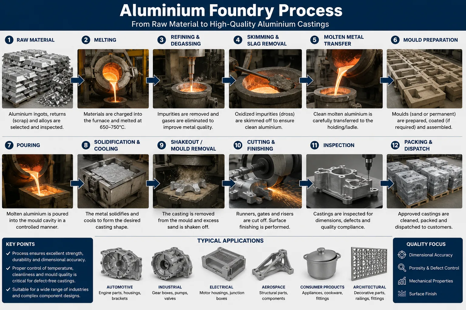
알루미늄 주조 공정은 용광로에서 알루미늄 합금을 용융하고, 용융 금속을 처리하여 용해된 수소와 비금속 함유물을 제거한 뒤, 처리된 용융물을 원하는 부품을 제작할 수 있도록 성형된 주형에 주입하거나 주입하는 과정을 포함합니다. 고형화 및 냉각 후, 주조품을 금형에서 분리하고, 열처리, 기계 가공 또는 표면 마감과 같은 추가 공정을 거친 뒤 완제품으로 납품됩니다.
Q2: 알루미늄의 가장 일반적인 주조 방법은 무엇입니까?
고압 다이캐스팅(HPDC)은 전 세계 총 생산량 기준으로 알루미늄 주조 분야에서 가장 널리 사용되는 주조 공법으로, 주로 자동차 및 전자 산업에서 얇은 벽 두께의 대량 생산 부품에 대한 수요가 이를 주도하고 있습니다. 모래 주조는 다양한 규모의 주조 공장에서 가장 널리 사용되는 방법이며, 크고 복잡한 부품이나 소량 생산 부품에 주로 선호됩니다. 저압 다이캐스팅은 알루미늄 합금 휠 제조에 주로 사용되는 방법입니다.
Q3: 주조 공장에서 가장 흔히 사용되는 알루미늄 합금은 무엇입니까?
A356 (AlSi7Mg0.3)은 뛰어난 주조성, T6 상태에서의 우수한 기계적 특성, 그리고 대부분의 주조 공법과 호환성을 모두 갖추고 있어 전 세계적으로 가장 널리 사용되는 주조 합금 중 하나입니다. A380(AlSi8Cu3Fe)은 뛰어난 유동성과 금형 충진 능력 덕분에 고압 다이캐스팅에 가장 일반적으로 사용되는 합금입니다.
Q4: 주조 전에 액체 알루미늄에서 수소는 어떻게 제거되나요?
수소는 회전식 탈기 공정을 통해 제거되는데, 이 공정에서는 회전하는 흑연 로터가 미세한 아르곤 또는 질소 기포를 용융물 전체에 분산시킵니다. 용융물에 용해된 수소는 이 기포들로 확산된 후, 기포가 상승하여 용융물 표면을 빠져나감에 따라 함께 제거됩니다. 이 처리를 통해 수소 함량은 공정 매개변수에 따라 10~25분 이내에 일반적으로 0.3~0.5 mL/100g Al에서 0.10~0.15 mL/100g Al 미만으로 감소합니다.
Q5: 알루미늄의 주조와 단조의 차이점은 무엇입니까?
알루미늄 주조품은 액체 금속을 주형에 붓거나 주입하여 생산되며, 금속은 응고 과정에서 주형의 형상을 따릅니다. 알루미늄 단조품은 다이를 사용하여 고압 하에서 고체 또는 반고체 상태의 알루미늄을 기계적으로 변형시켜 생산됩니다. 단조품은 변형 과정에서 결정립 구조가 미세해지고 기공이 제거되기 때문에, 일반적으로 동일한 형상의 주조품보다 강도가 높고 내피로성이 우수합니다. 반면 주조품은 더 복잡한 형상과 더 얇은 벽 두께를 구현할 수 있으며, 복잡한 형상의 경우 일반적으로 비용이 더 저렴합니다.
Q6: 알루미늄 주조품에 기공이 생기는 원인은 무엇이며, 이를 어떻게 방지할 수 있습니까?
알루미늄 주물의 기공은 두 가지 뚜렷한 원인으로 발생합니다. 기체 기공(매끄럽고 구형의 기공)은 응고 과정에서 용해된 수소가 침전되어 형성되며, 주조 전 적절한 탈기 처리를 통해 방지할 수 있습니다. 수축 기공(불규칙하고 서로 연결된 공극)은 응고 중인 금속이 부피 수축을 보상할 만큼 충분한 용융 금속을 흡수하지 못할 때 발생하며, 이는 주입점을 향한 방향성 응고를 보장하는 올바른 라이저 및 게이트 설계를 통해 방지할 수 있습니다. RPT(감압 시험) 및 X선 검사는 기공을 탐지하고 정량화하기 위한 표준 품질 관리 방법입니다.
Q7: 알루미늄 주조 공정에서 세라믹 폼 필터의 역할은 무엇입니까?
세라믹 폼 필터는 용광로와 주형 캐비티 사이의 금속 이송 시스템에 설치됩니다. 액체 알루미늄이 필터의 개방형 셀 폼 구조를 통과할 때, 고체 함유물(산화막, 내화물 입자, 금속간 화합물)은 기계적 선별과 표면 접착이 결합된 방식으로 포집됩니다. 이러한 여과 과정을 통해 용융물의 청정도가 크게 향상되어, 내포물 관련 결함이 감소하고 완성된 주조품의 기계적 특성, 특히 피로 수명과 연신율이 개선됩니다.
Q8: 알루미늄 주조 공정은 용융부터 완제품이 완성될 때까지 얼마나 걸리나요?
전체 사이클 시간은 전적으로 주조 방법과 부품의 복잡성에 따라 달라집니다. 고압 다이캐스팅의 경우 사이클 시간이 15~120초 정도 소요됩니다. 중력 다이캐스팅은 사이클당 2~10분이 필요합니다. 모래 주조의 경우, 대형 부품의 경우 완전히 응고되기까지 30분에서 수 시간이 걸릴 수 있습니다. 정밀 주조는 준비 시간이 가장 길지만(세라믹 쉘 제작에 며칠 소요), 실제 주조 공정은 신속하게 진행됩니다. 열처리는 T6 조건의 경우 8~20시간이 추가됩니다. 주문부터 가공이 완료된 부품이 나오기까지의 총 제조 리드 타임은 일반적으로 2일(HPDC)에서 수주(열처리 및 가공이 포함된 인베스트먼트 주조)까지 다양합니다.
Q9: 주조 공장에서 알루미늄은 몇 도에서 녹나요?
순수 알루미늄의 녹는점은 660°C입니다. 주조 현장에서는 알루미늄 합금을 일반적으로 700~780°C의 온도에서 가공하는데, 이는 완전한 용융과 주형 충진을 위한 적절한 유동성을 확보하기 위해 액상선 온도보다 높은 온도입니다. 온도가 높을수록 유동성은 향상되지만, 산화, 수소 흡수 및 에너지 소비가 증가합니다. 최적의 가공 온도는 합금마다 다르며, 사용되는 주조 공법에 따라 달라집니다. HPDC는 일반적으로 샷 슬리브에서 640~680°C로 작동하며(급속 응고 설계로 인해 용해로 온도보다 낮음), 반면 인베스트먼트 주조의 경우 복잡한 얇은 벽면 부위에 최대 780°C까지의 온도를 사용할 수 있습니다.
Q10: 알루미늄 주조 제품에는 어떤 품질 기준이 적용됩니까?
알루미늄 주조품은 용도 분야에 따라 다양한 품질 기준을 적용받습니다. 널리 참조되는 표준으로는 ASTM B85(알루미늄 합금 다이캐스팅), ASTM B108(영구 금형 주조), 항공우주용 주조에 대한 AMS 표준, 다이캐스팅 공차 및 검사에 대한 NADCA 표준, 그리고 GM, 포드 및 유럽 OEM과 같은 자동차 제조업체의 OEM별 표준이 있습니다. 용융물의 품질은 수소 함량(RPT 또는 Telegas로 검증) 및 내포물 수준(중요 용도의 경우 PoDFA 또는 Prefil 분석으로 검증)에 대한 주조소의 내부 사양에 따라 결정되는 경우가 많습니다. ASTM E505 또는 EN 12681에 따른 X선 및 CT 스캐닝은 구조용 주물의 기공을 검사하는 표준 방법입니다.
결론: 알루미늄 주조 요구 사항에 적합한 공정 선택
알루미늄 주조 공정은 단일한 방법이 아니라 서로 관련된 일련의 기술들로 구성되어 있으며, 각 기술은 고유한 장점, 한계, 비용 구조 및 품질 성능을 가지고 있습니다. 특정 부품에 대한 최적의 공정 선택은 다음 사항들에 대한 체계적인 평가를 통해 결정됩니다:
- 연간 생산량 (다이캐스팅 금형은 일정 수량 이상일 때만 비용 효율적입니다).
- 부품 형상의 복잡성과 벽 두께 요구 사항.
- 기계적 특성 및 열처리 요건.
- 치수 공차 및 표면 마감 사양.
- 적용 환경 (부식, 압력, 피로 하중).
- 금형 제작에 대한 예산 제약 및 단가.
요약 표 — 알루미늄 주조 공법 선정:
| 선정 기준 | 모래 | 중력 다이 | LPDC | HPDC | 투자 | 로스트 폼 |
|---|---|---|---|---|---|---|
| 기하학적 복잡도 | 높음 | 보통 | 보통 | 보통 | 매우 높음 | 높음 |
| 최소 벽 두께 | 3mm | 2.5mm | 2.0 mm | 0.8 mm | 0.5 mm | 2.5mm |
| 치수 정확도 | 낮음 | 보통 | Good | 매우 좋음 | 우수 | Good |
| 기계적 특성 | 보통 | Good | 매우 좋음 | 보통 | Good | Good |
| 열처리 가능 | 예 | 예 | 예 | 제한적 | 예 | 예 |
| 금형 비용 | 낮음 | 보통 | 높음 | 매우 높음 | 낮음-중간 | 낮음 |
| 최적의 부피 범위 | 1-5,000 | 500-50,000 | 5,000-200,000 | 50,000+ | 10-10,000 | 100-50,000 |
AdTech의 엔지니어링 팀은 4개 대륙에 걸쳐 알루미늄 주조 공장 및 주조 공정을 지원해 왔으며, 용융 품질 최적화, 적절한 주조 공정 선정, 그리고 각 생산 요구 사항에 맞는 여과, 탈가스 및 내화물 제품의 사양 결정 등을 도와드렸습니다. 저희는 단순한 카탈로그 사양을 넘어, 실무에 기반한 운영 지식을 모든 상담에 반영합니다.
