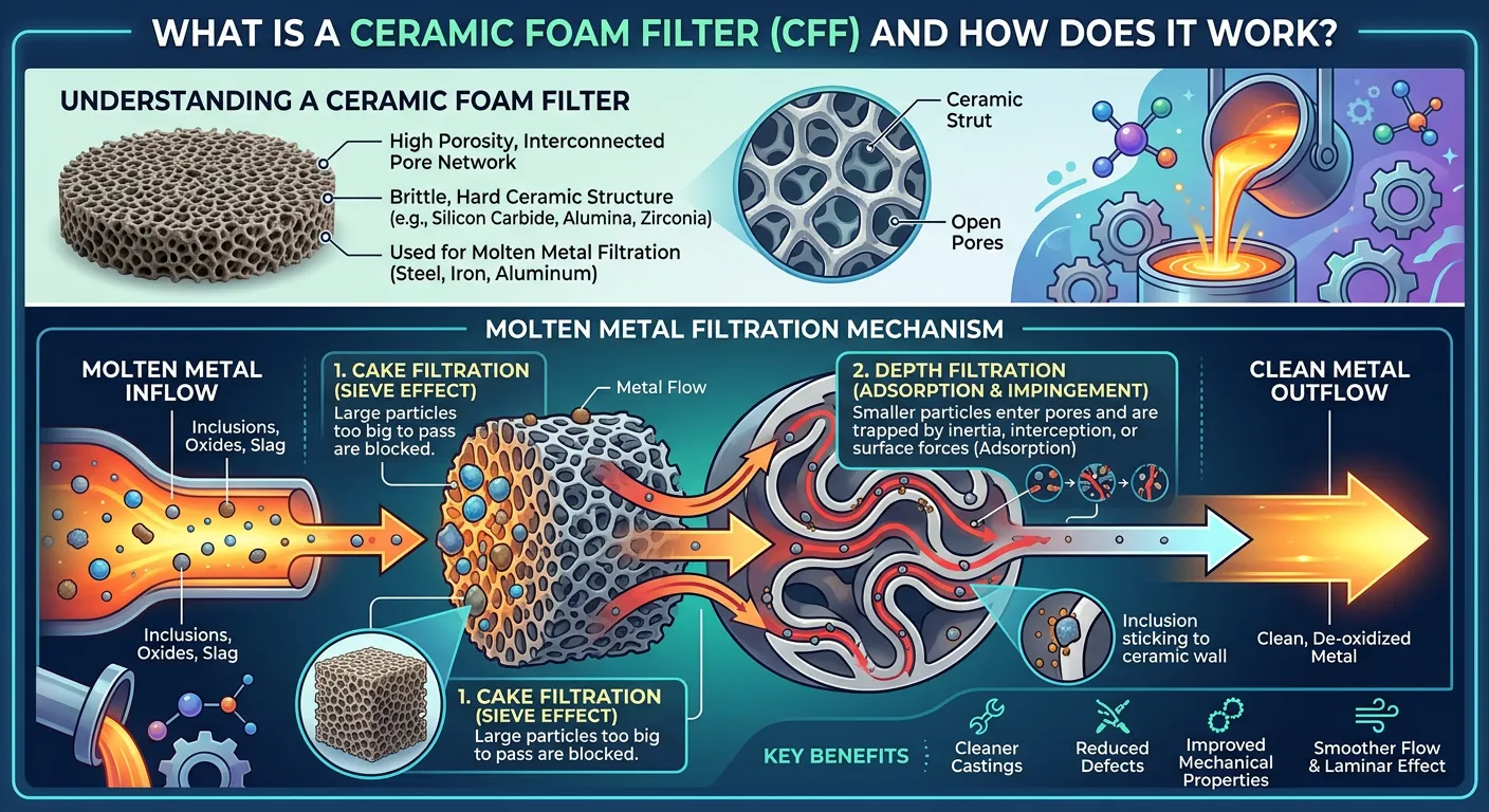
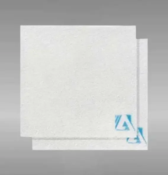
A ceramic foam filter (CFF) is a porous, three-dimensional reticulated structure made from advanced ceramic materials — most commonly alumina, silicon carbide, zirconia, or magnesia — specifically engineered to remove non-metallic inclusions, solid particles, and entrained gases from molten metal during the casting process. The filter works by forcing liquid metal through an interconnected network of tortuous flow paths, capturing inclusions through a combination of mechanical sieving, physical adhesion, and cake filtration mechanisms. The result is cleaner, higher-integrity castings with significantly reduced porosity, improved surface finish, and better mechanical properties.
If your project requires the use of Ceramic Foam Filter, you can contact us for a free quote.
In practical terms, ceramic foam filters are one of the most cost-effective quality improvement tools available in modern foundry and casting operations. We have evaluated filtration systems across aluminum, iron, steel, and copper alloy casting lines, and the evidence is consistent: integrating properly selected ceramic foam filters into a gating system reduces inclusion-related scrap rates by 40–80% while improving tensile strength, elongation, and fatigue life of the final casting. For industries where casting defects translate directly into field failures — aerospace components, automotive safety parts, and pressure-critical valves — that performance improvement is not optional.
What is a Ceramic Foam Filter and How Does It Work?
A ceramic foam filter occupies a unique position in casting technology because its structure is fundamentally different from conventional filtration media. Rather than a flat mesh or a simple perforated plate, a ceramic foam filter consists of an open-cell foam architecture — a continuous network of ceramic struts surrounding interconnected spherical voids — that replicates the geometry of a polyurethane foam template before firing.
The Three Filtration Mechanisms in Action
Understanding how ceramic foam filters actually capture inclusions requires looking at three simultaneous mechanisms:
Mechanical Sieving (Size Exclusion):
Inclusions larger than the filter pore opening are physically blocked at the filter face, forming a filter cake that itself becomes progressively more effective as metal flow continues. This is the most straightforward mechanism and applies primarily to larger inclusions (above 50–100 microns).
Tortuous Path Filtration (Depth Filtration):
This is where ceramic foam filters outperform simple mesh screens. The irregular, three-dimensional flow path forces molten metal to change direction repeatedly as it passes through the foam structure. Each direction change increases the probability that an inclusion particle will contact a ceramic strut surface and adhere to it. Inclusions as small as 10–20 microns are captured through this mechanism even when they are smaller than the nominal pore opening.
Wettability-Based Adhesion:
The ceramic surface chemistry of the filter material promotes adhesion of specific inclusion types. Alumina inclusions in aluminum melt, for example, adhere preferentially to alumina-based filter surfaces. This chemical affinity between filter substrate and inclusion type is a key reason why material selection matters far beyond temperature compatibility.
Flow Behavior Through the Filter
When molten metal first contacts the filter face, there is a brief priming period during which the metal overcomes surface tension and begins to wet the ceramic struts. Once flow is established, the pressure drop across the filter follows a modified Darcy relationship:
ΔP = (μ × L × v) / k
Where ΔP is pressure drop, μ is melt viscosity, L is filter thickness, v is flow velocity, and k is the permeability constant of the specific filter grade. In practical foundry terms, this means that filter placement in the gating system must account for the metallostatic pressure available to drive metal through the filter — insufficient head pressure results in incomplete filling or premature solidification.
Manufacturing Process: How Ceramic Foam Filters Are Made
The production of ceramic foam filters follows a process called the replica method (or polymer foam impregnation method), first developed and patented by Schwartzwalder and Somers in 1963. This manufacturing approach remains the industry standard more than six decades later, with significant refinements in slurry chemistry, binder systems, and firing control.
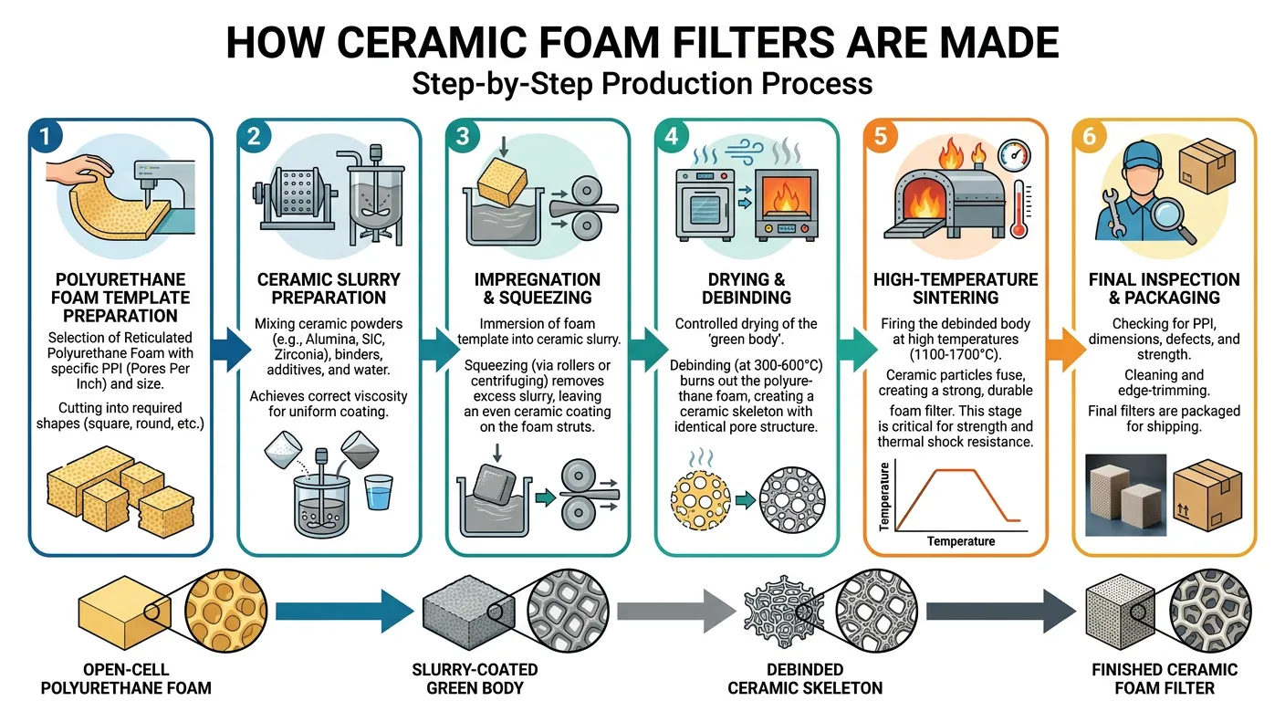
Stage 1: Polymer Foam Template Preparation
Open-cell polyurethane foam with the desired pore density (measured in PPI — pores per inch) is cut to the required dimensions. The foam template is inspected for uniform cell distribution and absence of closed pores, which would block metal flow in the final product.
Stage 2: Ceramic Slurry Preparation
A ceramic slurry is formulated from:
- Primary ceramic raw material (alumina, SiC, zirconia, etc.) in fine powder form.
- Colloidal silica, alumina sol, or phosphate binder.
- Rheology modifiers (bentonite, organic thickeners)
- Anti-foaming agents.
- Water or organic solvent carrier.
Slurry viscosity is precisely controlled — typically 1000–3000 cP for impregnation — to ensure complete cell coverage without blocking the pore openings.
Stage 3: Impregnation and Squeeze Coating
The polyurethane foam template is immersed in the ceramic slurry and manually or mechanically squeezed to ensure complete penetration of the slurry into all cells. Excess slurry is removed through controlled squeezing rolls to achieve the target coating weight and maintain open pore channels.
Stage 4: Drying
The impregnated foam is dried at 80–150°C to remove free water and develop sufficient green strength for handling. Drying must be controlled to prevent cracking from differential shrinkage stresses.
Stage 5: Burnout Firing (400–600°C)
The polyurethane foam template burns out completely during this stage, leaving behind the ceramic skeleton. This is a critical phase — if the organic burnout generates excessive internal gas pressure, the ceramic struts may crack before the structure is consolidated. Modern kilns use controlled atmosphere and slow heating rates through this range.
Stage 6: Sintering (1200–1650°C)
Final sintering densifies the ceramic struts, develops mechanical strength, and establishes the surface chemistry responsible for inclusion adhesion. The peak sintering temperature is matched to the specific ceramic system:
| Ceramic Material | Sintering Temperature Range |
|---|---|
| Alumina (Al₂O₃) | 1450–1600°C |
| Silicon Carbide (SiC) | 1900–2100°C (with sintering aids) |
| Zirconia (ZrO₂) | 1400–1550°C |
| Magnesia (MgO) | 1550–1650°C |
| Alumina-Silica (Mullite) | 1350–1500°C |
Stage 7: Quality Inspection and Sorting
Each filter undergoes visual inspection, dimensional measurement, and weight verification. Critical quality checks include:
- Pore size distribution uniformity.
- Absence of cracks or closed pores.
- Surface coating completeness.
- Dimensional tolerances (typically ±2mm on length/width, ±1mm on thickness)
Types of Ceramic Foam Filters by Material
Material selection is the first and most important decision in ceramic foam filter specification. Each ceramic system has a distinct operating temperature range, chemical compatibility profile, and filtration efficiency characteristic.
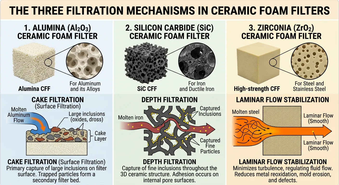
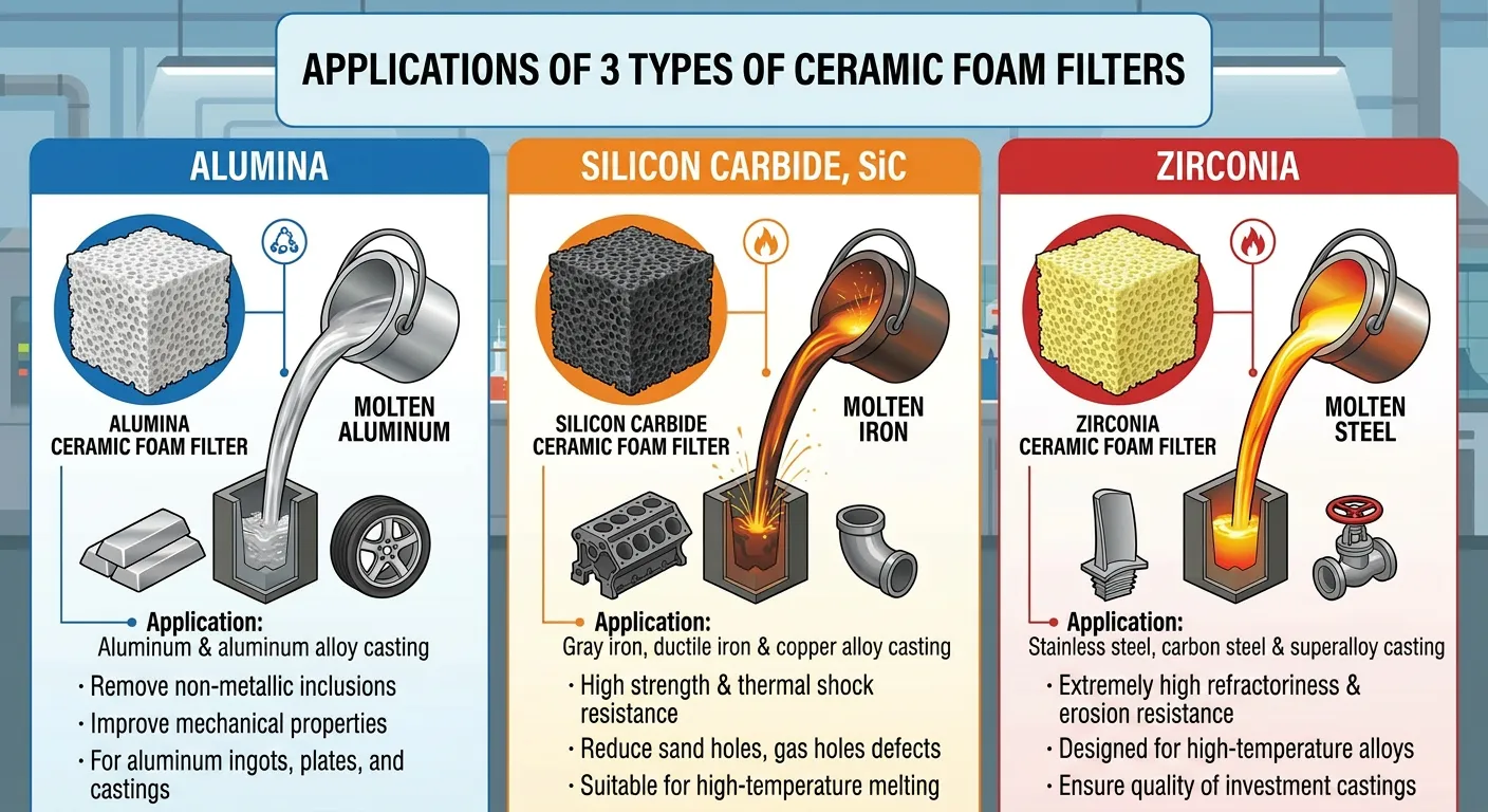
Alumina Ceramic Foam Filters
Alumina (Al₂O₃) ceramic foam filters are the most widely produced and used type globally, accounting for an estimated 60–70% of total ceramic foam filter consumption. Their dominance stems from an excellent combination of cost, temperature performance, and chemical compatibility with the majority of non-ferrous metal casting operations.
Primary Applications: Aluminum alloy casting, copper alloy casting, bronze casting
Key Properties:
- Maximum service temperature: 1100°C (for aluminum use), with high-purity grades up to 1700°C.
- Excellent chemical resistance to molten aluminum and its oxide inclusions.
- Natural affinity for alumina-type inclusions (the most common defect in Al castings).
- Available in 10–60 PPI range
Silicon Carbide (SiC) Ceramic Foam Filters
Silicon carbide filters stand apart from oxide-based filters through their exceptional thermal conductivity — approximately 10 times higher than alumina — and outstanding thermal shock resistance. These properties make SiC the material of choice for iron and some steel casting applications where thermal mass and rapid temperature changes are encountered.
Primary Applications: Gray iron, ductile iron, malleable iron casting.
Key Properties:
- Maximum service temperature: 1500°C.
- Thermal conductivity: 15–25 W/m·K (vs. 2–5 W/m·K for alumina).
- Superior thermal shock resistance reduces cracking risk during metal pour.
- SiC surface chemistry resists iron oxide inclusion adhesion (important for clean iron separation).
Zirconia Ceramic Foam Filters
Zirconia (ZrO₂) filters represent the premium tier of ceramic foam filtration, engineered for the most demanding high-temperature and chemically aggressive environments encountered in steel casting and specialty alloy processing.
Primary Applications: Steel casting, nickel-based superalloy casting, high-temperature specialty alloys.
Key Properties:
- Maximum service temperature: 1760°C+.
- Exceptional chemical resistance to molten steel slag and steel oxide inclusions.
- Low thermal conductivity (helps maintain metal temperature during filtration)
- Highest cost among standard ceramic foam filter types.
Magnesia (MgO) Ceramic Foam Filters
Magnesia-based filters are a specialty product category, primarily specified for steel casting applications where basic slag chemistry could attack alumina or silica-containing filter materials.
Primary Applications: Steel casting with basic slag conditions, specialty iron alloys
Key Properties:
- Maximum service temperature: 1750°C.
- Basic chemical character resists attack from basic slag.
- Higher density than alumina and zirconia options.
- Limited availability compared to other types.
Alumina-Silica (Mullite-Phase) Ceramic Foam Filters
Mullite-phase filters provide a cost-performance compromise between pure alumina and high-alumina grades. The mullite crystalline phase (3Al₂O₃·2SiO₂) delivers good thermal shock resistance and useful temperature capability at moderate cost.
Primary Applications: Medium-temperature aluminum alloy casting, copper alloys, some light iron applications
Material Selection Summary Table
| Filter Material | Max Service Temp | Primary Metal | Chemical Character | Relative Cost |
|---|---|---|---|---|
| Alumina (Al₂O₃) | 1100–1700°C | Aluminum, Copper | Neutral-Acidic | Low-Medium |
| Silicon Carbide (SiC) | 1500°C | Gray Iron, Ductile Iron | Neutral | Medium |
| Zirconia (ZrO₂) | 1760°C+ | Steel, Superalloys | Neutral-Basic | High |
| Magnesia (MgO) | 1750°C | Steel (basic slag) | Basic | Medium-High |
| Mullite (Al₂O₃-SiO₂) | 1400°C | Aluminum, Copper, Light Iron | Neutral | Low |
| Spinel (MgAl₂O₄) | 1700°C | Steel, Nickel Alloys | Neutral | High |
Pore Size (PPI) Ratings and What They Mean
PPI — pores per inch — is the primary specification parameter that determines filtration efficiency, flow resistance, and metal holding capacity of a ceramic foam filter. Understanding PPI selection is fundamental to optimizing filter performance in any casting application.
How PPI Is Measured and Defined
PPI refers to the number of pores (cells) counted along a linear inch of the filter cross-section. A 10 PPI filter has approximately 10 cells per inch, giving relatively large, open pore channels. A 30 PPI filter has approximately 30 cells per inch — much smaller pore openings with a correspondingly greater inclusion capture rate and higher flow resistance.
In practice, the actual pore size distribution within a single filter is not perfectly uniform. Most commercially produced filters have a ±15–20% variation in cell size across the filter face, which is normal and acceptable. Filters with tighter cell size distribution command a premium for critical applications.

PPI Rating Performance Comparison
| PPI Rating | Approx. Pore Size | Filtration Efficiency | Flow Resistance | Best Application |
|---|---|---|---|---|
| 10 PPI | 2.5–3.0 mm | Lower (coarse inclusions only) | Very Low | High flow rate, large castings |
| 20 PPI | 1.2–1.5 mm | Moderate | Low | General purpose, automotive parts |
| 25 PPI | 0.9–1.1 mm | Good | Moderate | Aluminum structural castings |
| 30 PPI | 0.7–0.9 mm | High | Moderate-High | Aerospace, pressure-tight parts |
| 40 PPI | 0.5–0.7 mm | Very High | High | Critical castings, medical |
| 50 PPI | 0.4–0.55 mm | Maximum | Very High | Superalloys, ultra-clean metal |
| 60 PPI | 0.3–0.4 mm | Maximum | Extremely High | Research, specialty applications |
Choosing PPI: Practical Decision Framework
The optimal PPI selection involves balancing three competing requirements:
1. Required Cleanliness Level: Higher cleanliness requirements push toward higher PPI ratings. Aerospace castings may specify 30–40 PPI, while general industrial castings may adequately use 20 PPI.
2. Available Metallostatic Pressure: Higher PPI means higher flow resistance. The available head pressure in the gating system must be sufficient to fill the mold cavity before solidification begins. We calculate minimum required head based on the specific filter dimensions and PPI rating before finalizing filter specification.
3. Metal Flow Rate Requirements: Large castings with thin sections require high flow rates. Specifying too high a PPI can starve the mold of metal, causing misruns and cold shuts — defects worse than some inclusions.
Key Performance Properties and Technical Specifications
When sourcing ceramic foam filters, procurement teams and engineers need to evaluate a standardized set of technical properties. Here is what matters most and why:
Thermal Properties
Thermal Shock Resistance:
Expressed as the number of thermal shock cycles a filter withstands without cracking under standardized test conditions (typically room temperature to 1000°C rapid immersion). SiC filters generally achieve 5–10+ cycles; alumina filters typically 3–6 cycles. Poor thermal shock resistance causes filter cracking during the pour, releasing ceramic fragments into the melt — which is far worse than no filtration at all.
Maximum Service Temperature:
The upper temperature limit at which the filter maintains structural integrity and does not contaminate the melt through dissolution or decomposition. Always verify this against the maximum pouring temperature of the specific alloy, with a minimum safety margin of 50°C.
Thermal Conductivity:
High thermal conductivity (SiC filters) minimizes temperature loss in the metal passing through the filter. Low thermal conductivity (zirconia) acts as a thermal insulator, maintaining metal temperature in the filter zone but potentially accelerating solidification at the filter face.
Mechanical Properties
| Property | Test Method | Typical Range | Significance |
|---|---|---|---|
| Cold Compressive Strength | ASTM C133 | 0.5–2.5 MPa | Handling and installation resistance |
| Hot Modulus of Rupture | ASTM C583 | 0.3–1.5 MPa | Structural integrity during pour |
| Bulk Density | ISO 5017 | 0.25–0.45 g/cm³ | Indirect porosity indicator |
| Total Porosity | Archimedes method | 75–90% | Higher porosity = higher flow rate |
| Specific Surface Area | BET method | 0.3–1.5 m²/g | Influences inclusion capture area |
Filtration Performance Properties
Filtration Efficiency (FE):
The percentage of inclusions removed from a metal sample passing through the filter compared to an unfiltered reference. Measured through metallographic analysis of K-value (reduced pressure test) or PoDFA (Prefil-Footprinter) analysis before and after filtration.
Priming Pressure:
The minimum metallostatic pressure required to initiate metal flow through the filter. This value must be exceeded in the gating system design. Typical values: 50–150 mm of metal head, depending on PPI and metal surface tension.
Metal Holding Capacity:
The maximum mass of inclusions the filter can capture before becoming fully blocked. Expressed in grams of inclusion per square centimeter of filter face area.
How Ceramic Foam Filters Improve Casting Quality
The connection between ceramic foam filtration and final casting quality is well-documented in peer-reviewed metallurgical literature and supported by decades of foundry production data. Here is a quantified look at what filtration actually delivers:
Inclusion Removal and Metal Cleanliness
Non-metallic inclusions are the most common and damaging source of casting defects. They originate from multiple sources:
- Oxide films: Formed when molten metal contacts oxygen during pouring
- Refractory erosion products: From ladles, runners, and riser sleeves
- Slag entrainment: Carried in from melting furnace
- Dross: Partially solidified metal skin folded into the melt stream
- Intermetallic compounds: Precipitated from alloy chemistry imbalances
Ceramic foam filters interrupt the transport of these inclusions from the gating system to the mold cavity. Published data from multiple sources shows:
| Casting Parameter | Without Filter | With 30 PPI Filter | Improvement |
|---|---|---|---|
| Tensile Strength (Al A356) | 215 MPa | 248 MPa | +15% |
| Elongation at Break | 4.5% | 7.2% | +60% |
| Fatigue Life (cycles to failure) | 85,000 | 140,000 | +65% |
| Porosity Area Fraction | 0.8% | 0.2% | -75% |
| Inclusion Count (per cm²) | 12.4 | 2.1 | -83% |
| Surface Roughness (Ra) | 6.3 μm | 4.1 μm | -35% |
Data aggregated from published foundry industry studies, 2018–2024.
Turbulence Reduction and Flow Regularization
Beyond inclusion capture, ceramic foam filters fundamentally alter the flow character of metal entering the mold. Unfiltered metal enters a mold cavity in a turbulent, chaotic stream that entrains air and folds oxide films. The filter converts this turbulent flow into a smooth, laminar stream — a transformation that prevents new inclusions from forming downstream of the filter.
This turbulence damping effect is sometimes more valuable than the direct inclusion removal, particularly in long-flow casting configurations where oxide film generation during filling is the dominant defect mechanism.
Thermal Regulation Benefits
In iron casting applications specifically, SiC ceramic foam filters act as a preheating reservoir for the metal stream. The high thermal mass and conductivity of the filter briefly contacts and slightly superheats the metal in contact with the hot filter surface during steady-state pour, helping maintain mold fill before solidification begins in thin sections.
Industrial Applications and Metal-Specific Uses
Aluminum Casting Industry
The aluminum casting industry is the largest global consumer of ceramic foam filters by volume, driven by the explosive growth in aluminum automotive components and aerospace structural parts. The typical application involves alumina ceramic foam filters at 20–40 PPI positioned in the runner system of gravity, low-pressure, or high-pressure die casting tooling.
Key aluminum alloy families filtered:
- A356/A357 (structural automotive components)
- 319, 380 series (engine blocks, transmission housings)
- 2xxx and 7xxx series wrought alloys (aerospace billets)
- 6xxx series extrusion billets.
Specific filtration benefit in aluminum: The primary inclusion in aluminum is aluminium oxide (Al₂O₃) in bifilm and dispersed particle forms. Alumina filter material shares chemistry with these inclusions, promoting preferential adhesion and high capture efficiency.
Iron and Ductile Iron Casting
Iron foundries use silicon carbide ceramic foam filters to manage graphite inclusions, slag, and sand erosion products. The high pouring temperatures of gray iron (1300–1400°C) and ductile iron (1380–1450°C) demand the thermal shock resistance that SiC filters provide.
Applications in iron casting:
- Automotive brake discs and drums.
- Engine blocks and cylinder heads.
- Pipes and fittings.
- Agricultural equipment components.
- Pump housings and valve bodies.
Steel Casting
Steel presents the most demanding filtration environment: pouring temperatures of 1550–1650°C, aggressive oxidizing slag, and high metallostatic pressure. Zirconia ceramic foam filters are the standard choice, often used in combination with fibrous refractory filter seats and ceramic dams.
Applications in steel casting:
- Mining wear parts (crusher jaws, mill liners)
- Railway components (wheels, bogies)
- Pressure vessel components.
- Industrial pump and valve bodies.
- Defense and ballistic protection components.
Copper and Copper Alloy Casting
Copper alloys including brass, bronze, and copper-nickel alloys are filtered using alumina or mullite ceramic foam filters at relatively lower temperatures (1000–1200°C pouring). Filtration in copper alloy casting specifically targets:
- Sand inclusions from mold erosion
- Oxide skins formed during pouring
- Refractory erosion products
Nickel and Titanium Superalloy Investment Casting
The aerospace investment casting sector uses the finest PPI ratings (40–60 PPI) with high-purity zirconia or spinel ceramic foam filters for producing turbine blades, vanes, and structural airframe components. The absolute cleanliness requirements for these parts — where a single significant inclusion can cause catastrophic fatigue failure — justify the use of the highest-performance filtration systems available.
How to Select the Right Ceramic Foam Filter
Selection of the optimal ceramic foam filter requires a structured evaluation process rather than simple product lookup.
Step 1: Identify the Casting Metal and Pouring Temperature
| Metal Category | Pouring Temperature Range | Recommended Filter Material |
|---|---|---|
| Aluminum alloys | 680–780°C | Alumina (Al₂O₃) |
| Copper alloys | 1000–1200°C | Alumina or Mullite |
| Gray/Ductile Iron | 1300–1450°C | Silicon Carbide (SiC) |
| Carbon/Low-Alloy Steel | 1550–1620°C | Zirconia (ZrO₂) |
| Stainless Steel | 1580–1650°C | Zirconia (ZrO₂) |
| Nickel Superalloys | 1400–1550°C | Zirconia or Spinel |
| Titanium Alloys | 1650–1700°C | Yttria-stabilized ZrO₂ |
Step 2: Determine Required Filtration Level
Consider the end-use requirements of the casting. Structural aerospace components need maximum filtration efficiency (30–40 PPI). General industrial castings may be adequately served by 20 PPI. Decorative non-load-bearing castings may use 10–15 PPI for flow control without aggressive filtration.
Step 3: Calculate Required Filter Area
The filter face area must be sufficient to pass the required metal volume within the available fill time without exceeding the maximum permissible flow velocity. A commonly used guideline:
Minimum Filter Area (cm²) = Metal Mass (kg) / (Fill Time (sec) × Maximum Flow Rate Factor)
For aluminum with a 20 PPI filter, the typical maximum flow rate is approximately 0.3–0.5 kg/cm²/second. Undersizing the filter is a common error that causes back pressure buildup, mold misfill, and filter fracture.
Step 4: Specify Dimensions and Thickness
Standard ceramic foam filter dimensions follow industry conventions, though custom sizes are available:
| Standard Sizes (mm) | Thickness Options (mm) | Common Application |
|---|---|---|
| 40 × 40 | 15, 22 | Small castings, runners |
| 50 × 50 | 15, 22 | General purpose |
| 75 × 75 | 15, 22, 25 | Medium castings |
| 100 × 100 | 22, 25 | Automotive, structural |
| 150 × 150 | 22, 25 | Large iron castings |
| 200 × 200 | 25 | Very large castings |
| Round: Ø40–Ø230 | 15–25 | Ladle well blocks, specialized |
Installation, Gating System Integration, and Best Practices
Correct installation is as important as correct filter selection. A high-quality filter improperly positioned in the gating system delivers far less than its potential performance.
Filter Seat Design
The filter seat is the recess in the runner bar or dedicated filter housing that positions and retains the filter. Critical seat design principles:
Seal Integrity: The filter must sit in a seat that prevents metal from bypassing around the filter edges. Even a 1mm gap between filter edge and seat allows metal to channel around the filter, dramatically reducing effective filtration efficiency. We recommend a seat depth of 2–3mm and a seat width of 3–5mm beyond the filter dimension on each side.
Filter Support: The downstream runner must provide adequate support area to prevent filter fracture under the hydraulic pressure of metal flow. Minimum support contact: 20% of filter face area.
Venting: Air trapped below the filter before metal arrival must have a vent path to escape. Without venting, back pressure from trapped air delays filter priming and can cause turbulence during the initial fill phase.
Positioning in the Gating System
| Filter Position | Advantages | Limitations |
|---|---|---|
| Sprue base | Catches all inclusions early | High velocity metal arrival, thermal shock risk |
| Runner bar | Most common position, good head pressure | Must account for metal cooling in long runners |
| Ingate position | Filters metal immediately before cavity | Small filter area, high flow rate per unit area |
| Riser base | Filters during feeding phase | Less effective for fill-related defects |
Pre-Heating Filters
In steel and high-temperature iron casting, pre-heating ceramic foam filters to 200–400°C before placing them in the mold assembly reduces thermal shock during the initial metal contact. For aluminum casting, pre-heating is generally not required, but avoiding contact with moisture or cold surfaces before installation prevents thermal shock-induced cracking.
Handling and Storage
- Always handle ceramic foam filters with clean gloves — oil contamination from skin can interfere with metal wetting.
- Store in dry conditions at ambient temperature in original packaging.
- Do not stack more than 10 filters per column to prevent crushing under weight.
- Check for cracks or damage before installation — damaged filters must be discarded.
Comparing Ceramic Foam Filters to Other Filtration Methods
Understanding where ceramic foam filters outperform alternatives helps engineers make justified specification decisions.
Comparison Table: Filtration Methods for Metal Casting
| Parameter | Ceramic Foam Filter | Fibrous Filter (Fiberglass) | Extruded Ceramic Filter | Strainer Core | No Filter |
|---|---|---|---|---|---|
| Temperature Limit | Up to 1760°C | Up to 1000°C | Up to 1600°C | Up to 1500°C | N/A |
| Inclusion Removal | Excellent | Good | Moderate | Poor-Moderate | None |
| Flow Resistance | Moderate | Low | Moderate-High | Low-Moderate | None |
| Turbulence Damping | Excellent | Moderate | Moderate | Poor | None |
| Thermal Shock Resistance | Good-Excellent | Poor | Moderate | Good | N/A |
| Cost Per Filter | Moderate | Low | Low-Moderate | Very Low | None |
| Available for Steel? | Yes (Zirconia) | No | Limited | Limited | Yes |
| Surface Area for Capture | Very High | Moderate | Low | Very Low | None |
| Relative Filtration Efficiency | 100% reference | 40–60% | 30–50% | 10–20% | 0% |
Why Ceramic Foam Wins in High-Demand Applications
The combination of three-dimensional tortuous path, high specific surface area, and high-temperature capability makes ceramic foam the definitive choice for castings where cleanliness directly impacts mechanical performance. The only scenario where alternative filtration may be preferred is extremely high flow rate applications where the pressure drop of a foam filter would restrict fill — in these cases, extruded honeycomb filters may be substituted.
Quality Standards, Testing, and Certification
Applicable International Standards
| Standard | Organization | Scope |
|---|---|---|
| ISO 26910 | ISO | Ceramic foam filters for metal casting — requirements |
| ASTM C1674 | ASTM | Flexural strength of advanced ceramics with open porosity |
| GB/T 25139 | China GB | Ceramic foam filters for aluminum alloy casting |
| GB/T 30840 | China GB | Ceramic foam filters for iron and steel casting |
| EN 993-1 | European | Physical testing of dense shaped refractory products |
| JIS R 2412 | Japanese | Ceramic filter products for molten metal |
Key Quality Tests for Incoming Inspection
Visual Inspection:
100% of filters should be visually inspected for cracks, incomplete coating, closed pores, and dimensional compliance. We recommend using a standardized light table inspection setup for high-volume foundry operations.
Dimensional Verification:
Random sampling of 5–10% of received filters for dimensional measurement against drawing tolerances.
Compressive Strength Testing:
Random sample lot testing using ASTM C133 or equivalent. Minimum acceptable cold compressive strength varies by material and application.
Pore Count Verification:
PPI rating verification through standardized cell counting across multiple sections of sample filters. Variation of more than ±2 PPI from nominal rating is cause for rejection.
Thermal Shock Testing:
For critical applications, pre-qualification thermal shock testing of filter lots exposed to rapid temperature change cycles confirms resistance to cracking during actual pour conditions.
Also read:
Procurement Guide: Sizing, Pricing, and Supplier Evaluation
Pricing Overview (2026 Market Reference)
| Filter Type | Size Range | Approximate Unit Price Range |
|---|---|---|
| Alumina, 20–30 PPI | 50×50×22mm | $0.15–0.45 USD |
| Alumina, 20–30 PPI | 100×100×22mm | $0.50–1.20 USD |
| SiC, 20–30 PPI | 100×100×22mm | $0.80–2.00 USD |
| Zirconia, 30 PPI | 100×100×22mm | $3.00–8.00 USD |
| Zirconia, 40 PPI | 150×150×25mm | $8.00–20.00 USD |
| Custom sizes | Various | 30–100% premium over standard |
Prices vary significantly by order volume, supplier region, and raw material market conditions.
Supplier Evaluation Framework
When assessing ceramic foam filter suppliers, we apply the following criteria structure:
Technical Capability:
- Range of materials and PPI grades offered.
- Dimensional range and custom capability.
- In-house testing laboratory with published test methods.
- Technical data sheets with complete property listings.
Quality Management:
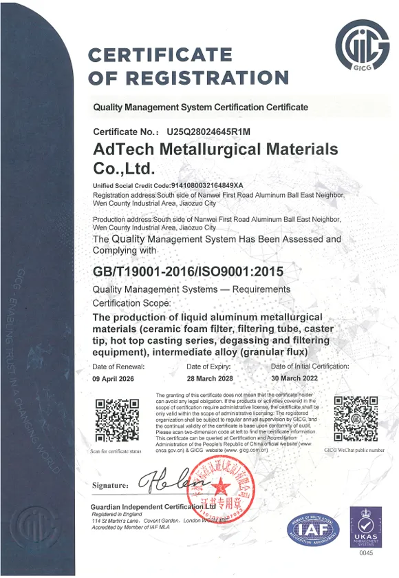
- ISO 9001 certification as minimum.
- Batch traceability system.
- Certificate of conformance with each shipment.
- Defined sampling and acceptance criteria.
Supply Reliability:
- Regional warehouse or local stock availability.
- Minimum order quantity requirements.
- Lead time for standard and custom products.
- Track record of delivery performance.
Technical Support:
- Application engineering support capability.
- Willingness to conduct foundry trials and performance evaluation.
- Published case studies or application references.
Common Ordering Mistakes to Avoid
- Specifying only material and PPI without temperature verification: Always confirm the filter’s rated maximum service temperature against actual pouring temperature.
- Undersizing filter area to save cost: The cost of one failed casting far exceeds the cost difference between a correctly sized and undersized filter.
- Ignoring moisture during storage: Wet ceramic filters can fracture explosively when contacted by molten metal.
- Mixing filter types from different lots in the same production run: Property variations between lots can cause inconsistent results.
- Overlooking filter seat design: Even the best filter performs poorly in a poorly designed seat.
Frequently Asked Questions (FAQs)
Q1: What is the primary purpose of a ceramic foam filter in metal casting?
The primary purpose is to remove non-metallic inclusions — oxide particles, slag fragments, sand grains, and refractory erosion products — from molten metal before it enters the mold cavity. A secondary but equally important function is converting turbulent metal flow into a smooth, laminar stream that prevents new oxide formation during mold filling. Together, these functions reduce casting defects and improve the mechanical properties of the finished part.
Q2: Can ceramic foam filters be reused in production?
No. Ceramic foam filters are single-use consumables. Once a filter has passed molten metal, its pores are partially or fully saturated with captured inclusions and solidified metal. Attempting to reuse a filter would expose the casting to those captured inclusions plus any additional contamination from the degraded filter structure. The cost of a filter is a small fraction of the casting value, making reuse economically unjustifiable in any production context.
Q3: What PPI rating should I use for aluminum casting?
For most structural aluminum casting applications — automotive suspension parts, engine brackets, and similar components — a 20–30 PPI alumina ceramic foam filter delivers the best balance of inclusion removal and flow rate. For aerospace or safety-critical applications requiring the highest cleanliness, 30–40 PPI is appropriate. For simple non-structural decorative castings, 10–20 PPI is often sufficient.
Q4: What is the difference between a ceramic foam filter and an extruded ceramic filter?
A ceramic foam filter has a three-dimensional, irregular, reticulated pore structure created by the replica foam method. This tortuous path provides deep filtration, capturing inclusions smaller than the nominal pore size. An extruded ceramic filter has straight, parallel channels — like a honeycomb — that only allow surface sieving of inclusions larger than the channel opening. Ceramic foam filters are significantly more effective for fine inclusion removal but have higher flow resistance than extruded alternatives.
Q5: How do I know if my ceramic foam filter has worked effectively?
Post-casting evaluation methods include: metallographic examination of cross-sections from the casting (counting and sizing inclusions), reduced pressure testing (K-value) of metal samples taken before and after the filter position, and PoDFA or LAIS analysis in aluminum casting operations. A simpler field indicator is examining the filter after casting — a heavily loaded filter face with visible inclusion buildup confirms active capture.
Q6: What causes a ceramic foam filter to crack during pouring?
Cracking during pouring is most commonly caused by thermal shock when cold or room-temperature filters contact hot molten metal. The rapid temperature rise creates thermal gradient stresses that exceed the filter’s modulus of rupture. Prevention strategies include pre-heating the filter assembly, ensuring the filter is completely dry before use, and using silicon carbide filters (with superior thermal shock resistance) for iron and steel applications.
Q7: Do ceramic foam filters affect metal temperature?
Yes, to a measurable but manageable degree. Metal passing through a room-temperature ceramic foam filter loses some thermal energy to the filter mass during the initial pour phase. For aluminum at typical volumes, this temperature loss is typically 3–8°C across the filter. For iron and steel with their much higher thermal mass of metal, the effect is smaller proportionally. In most production casting operations, this temperature drop is accounted for in the pouring temperature specification.
Q8: Are ceramic foam filters suitable for high-pressure die casting (HPDC)?
No. Standard ceramic foam filters are not used in high-pressure die casting because the injection velocities and pressures (up to 150 MPa) would immediately fracture any ceramic foam structure. Filtration in HPDC is achieved through other means: vacuum systems, optimized gating design, and degassing equipment. Ceramic foam filters are appropriate for gravity die casting, low-pressure die casting (LPDC), investment casting, and sand casting processes.
Q9: What is the environmental impact of ceramic foam filter disposal?
Used ceramic foam filters are classified as solid industrial waste. After casting, filters contain solidified metal inclusions and possibly small amounts of metal. In most jurisdictions, they are disposed of as non-hazardous industrial waste in licensed facilities. Some foundries recover residual metal value through recycling of high-metal-content used filters. The ceramic material itself is chemically stable and does not leach hazardous components, making landfill disposal generally acceptable under standard industrial waste regulations.
Q10: Can ceramic foam filters be customized for unusual shapes or sizes?
Yes. While standard square and rectangular sizes are most common and economical, ceramic foam filters can be manufactured in round, oval, trapezoidal, and other custom geometries. Minimum order quantities for custom sizes are typically 500–2000 pieces depending on complexity. Lead times for custom tooling and initial production run from 4–12 weeks. For very high-volume custom applications, the economics of custom sizing typically justify the tooling investment within the first production year.
Conclusion
Ceramic foam filters occupy a critical position in modern metal casting quality systems. Their ability to simultaneously remove inclusions, regularize metal flow, and improve casting mechanical properties makes them one of the few consumable components where investment directly and measurably increases product quality and reduces scrap cost.
The key takeaways for engineers: material selection must match both metal chemistry and operating temperature; PPI selection must balance cleanliness requirements against available gating pressure; and filter sizing must be calculated rather than estimated. For procurement professionals: unit cost per filter is a misleading metric — total value calculation must include scrap rate reduction, machining yield improvement, and warranty claim reduction attributable to cleaner castings.
At AdTech, we work with foundries and casting operations across aluminum, iron, steel, and specialty alloy sectors. The consistent lesson from that experience is straightforward: a well-specified ceramic foam filter, correctly installed, pays for itself many times over in every casting cycle.
