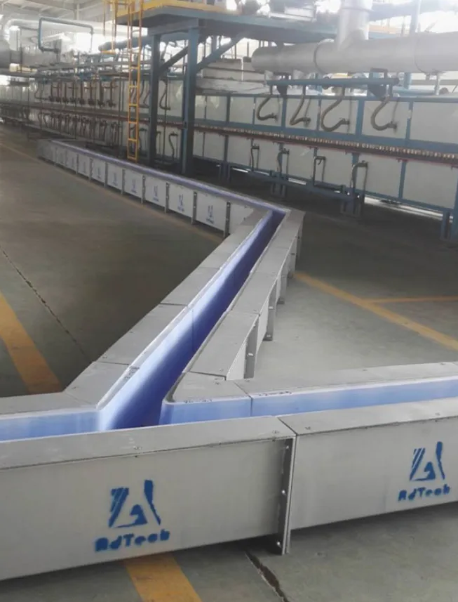
AdTech’s custom molten aluminum transfer launder system represents the most advanced solution for safe, efficient, and contamination-free liquid aluminum transportation in modern aluminum smelting and casting operations. Our engineered launder systems combine refractory-lined channels, precision thermal management, and modular configuration capabilities to reduce aluminum oxidation losses by up to 35%, maintain melt temperature within ±5°C, and extend service life beyond 10 years under continuous industrial conditions.
If your project requires the use of Aluminum Transfer Launder, you can contact us for a free quote.
What Is a Molten Aluminum Transfer Launder System?
A molten aluminum transfer launder system is a purpose-built channel network that moves liquid aluminum at temperatures between 680°C and 780°C from a holding or melting furnace to a casting machine, degassing unit, or filtration station without compromising melt chemistry or temperature. Unlike simple troughs or manually handled ladles, an engineered launder system is a permanent or semi-permanent infrastructure component that integrates into the casting production line as a continuous flow conduit.
At AdTech, we have spent more than a decade refining our launder engineering methodology. The fundamental challenge our clients face is that molten aluminum is chemically reactive, thermally sensitive, and structurally demanding on any containing material. A poorly designed channel creates turbulence that entrains oxides, allows heat loss that promotes premature solidification, and absorbs contaminants from incompatible lining materials. Every one of these failure modes leads directly to casting defects, scrap generation, and production downtime.
The launder system addresses these challenges through four integrated engineering disciplines: refractory material science, thermal systems engineering, fluid dynamics modeling, and structural fabrication. When all four are executed correctly, the launder becomes an invisible but critical part of a high-throughput aluminum casting line.
What Types of Launders Exist in Industrial Aluminum Production?
Industrial aluminum transfer launders fall into several distinct categories based on function, geometry, and installation method:
| Launder Type | Primary Function | Typical Length | Operating Temperature |
|---|---|---|---|
| Straight Channel Launder | Point-to-point melt transfer | 1–20 meters | 700–760°C |
| Curved/Angled Launder | Layout-constrained routing | Custom | 700–760°C |
| Heated Launder (Gas/Electric) | Long-distance transfer with heat maintenance | 5–50 meters | 700–780°C |
| Insulated Launder (Passive) | Short transfers with minimal heat loss | 1–10 meters | 680–750°C |
| Degassing Launder | Inline hydrogen removal | 2–8 meters | 710–760°C |
| Filtration Launder | Inline ceramic foam filtration | 1–4 meters | 700–750°C |
| Tundish/Distribution Launder | Multi-strand casting distribution | Custom | 700–770°C |
We manufacture all categories listed above with standardized base modules and customizable end configurations. The selection between a heated and passive insulated launder, for example, depends on transfer distance, ambient temperature, alloy sensitivity, and flow rate, all of which our engineering team calculates before any fabrication begins.
Why Does Launder Design Directly Affect Aluminum Casting Quality?
This is the question that separates buyers who understand aluminum metallurgy from those who treat the launder as a simple plumbing component. The launder is not a neutral pipe. It is an active participant in the metallurgical condition of your melt.
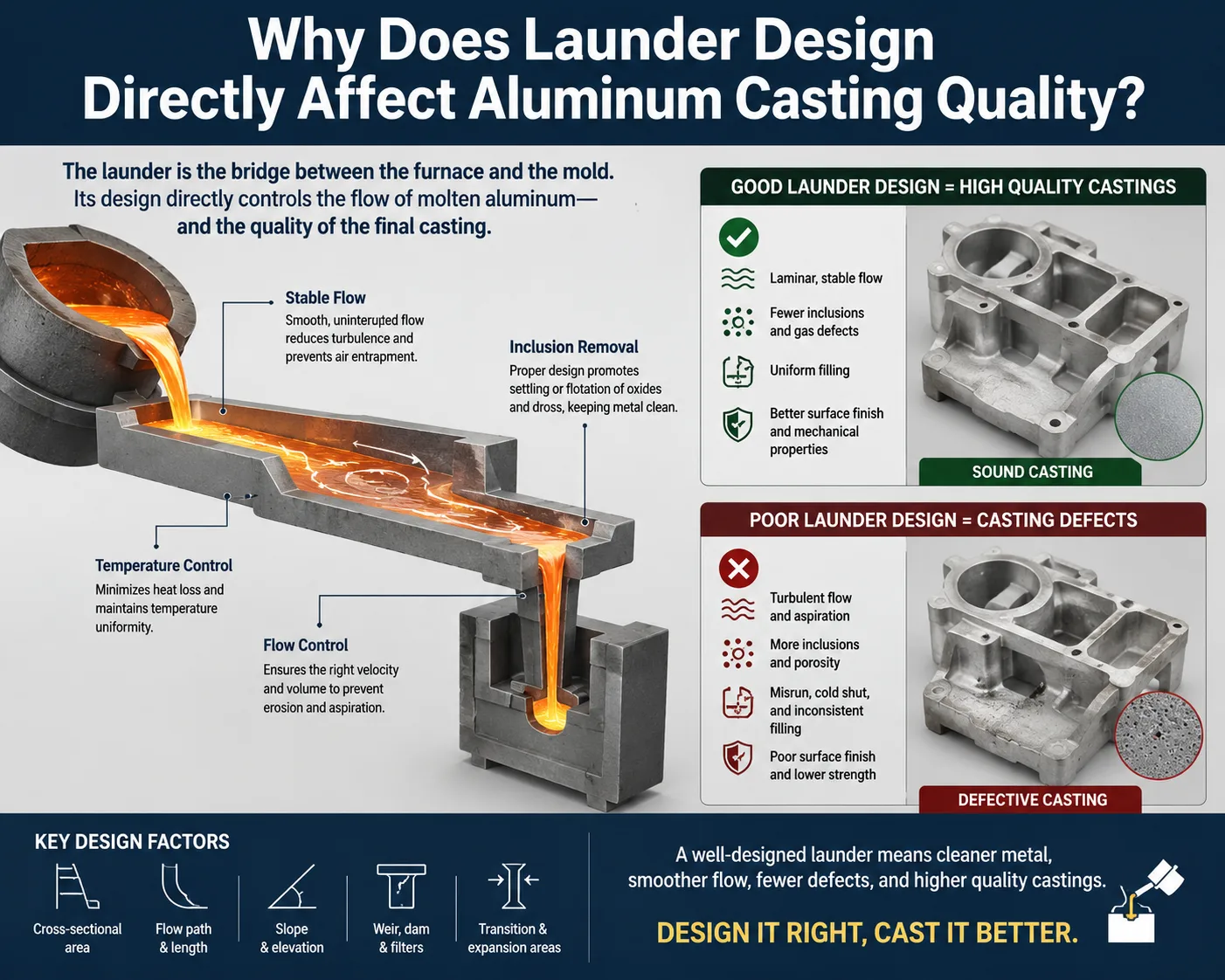
How Turbulence in the Launder Channel Generates Oxide Inclusions
Molten aluminum oxidizes immediately when its surface contacts atmosphere. The oxidation rate accelerates dramatically when the melt surface is disturbed. A poorly designed launder with abrupt changes in cross-section, excessive slope, or rough interior surfaces creates turbulent flow conditions that fold surface oxide films into the bulk melt. These folded oxide films, known as bifilms, are among the most damaging inclusion types in aluminum castings. They reduce tensile strength, elongation, and fatigue life in the final product.
Research published in the International Journal of Metalcasting demonstrates that bifilm content in cast aluminum increases by 60–120% when melt flow velocity exceeds 0.5 m/s without flow control measures. Our launder systems are designed with flow velocity targets below 0.3 m/s at all points, achieved through precise calculation of channel cross-section, slope angle, and transition geometry.
What Happens When Melt Temperature Drops Below Target During Transfer?
Temperature loss during transfer is not simply a comfort problem. When aluminum alloys cool below their liquidus temperature, they begin forming dendritic solid networks. Even partial solidification events that subsequently remelt leave behind oxide-rich zones and microstructural heterogeneity that weakens cast products.
For aluminum alloy 6063, for example, the liquidus temperature is approximately 655°C and the solidus is approximately 615°C. A launder that allows the melt to drop to 640°C during a 15-meter transfer creates a partially solidified front that then remixes with hotter incoming metal. The result is an inconsistent melt temperature entering the casting machine, leading to variation in cooling rate, grain structure, and mechanical properties from billet to billet.
Our heated launder systems maintain temperature within ±5°C over transfer distances up to 50 meters. This is verified by embedded thermocouple arrays that our monitoring systems log continuously.
What Materials Are Used in Refractory Lining for Aluminum Launders?
The refractory lining is the most technically critical component of any molten aluminum launder. It must simultaneously resist chemical attack from liquid aluminum, maintain dimensional stability under thermal cycling, provide low thermal conductivity to minimize heat loss, and release no contaminants into the melt.
Comparison of Refractory Materials Commonly Used in Aluminum Launders
| Material | Aluminum Wetting Resistance | Thermal Conductivity (W/m·K) | Max Service Temperature | Typical Service Life |
|---|---|---|---|---|
| Fused Silica | Excellent | 1.4–1.7 | 1050°C | 5–8 years |
| High-Alumina Castable | Good | 1.8–2.5 | 1400°C | 3–6 years |
| Calcium Silicate Board | Good | 0.12–0.18 | 870°C | 2–4 years (backup layer) |
| Silicon Carbide (SiC) | Excellent | 15–25 | 1650°C | 8–12 years |
| Boron Nitride Coating | Superior | 30–60 | 2000°C+ | Depends on substrate |
| Fused Alumina | Very Good | 2.0–3.5 | 1800°C | 4–8 years |
AdTech uses fused silica as the primary channel lining material in most standard applications because it offers the ideal balance of aluminum non-wetting behavior, thermal expansion compatibility, and cost-effectiveness over a 10-year service horizon. For aggressive high-silicon alloys or applications involving elevated processing temperatures, we specify SiC-enhanced formulations that our materials laboratory has tested under simulated production conditions.
Why Thermal Expansion Compatibility Matters More Than Raw Strength
A common misconception among procurement teams is that a harder, denser refractory material is always better. In aluminum launder applications, thermal expansion mismatch between the structural shell and the refractory lining creates internal stress that leads to cracking, spalling, and ultimately lining failure. Our engineering team calculates the coefficient of thermal expansion (CTE) for every material layer in the launder assembly and designs expansion joint spacing to accommodate the thermal cycling between cold installation state and operating temperature.
We use finite element thermal modeling to simulate 500 heat-up and cool-down cycles before finalizing a lining specification. This predictive approach has allowed us to extend average lining service life from the industry standard of 3–5 years to 8–12 years in multiple client installations.
How Does AdTech Engineer a Custom Launder System from Specification to Installation?
Our engineering process follows a structured methodology that we have refined across more than 200 custom launder projects worldwide. The process is not a one-size-fits-all template but a discipline-by-discipline analysis that produces a unique solution for each client’s production conditions.
Phase 1: Site Survey and Process Data Collection
Before any design work begins, our engineering team collects:
- Furnace tap-hole height and geometry.
- Casting machine inlet height and location.
- Available floor space and routing constraints.
- Alloy compositions being processed.
- Casting rates (kg/min or tonnes/hour)
- Maximum and minimum melt temperature requirements
- Existing infrastructure (gas supply, electrical capacity, crane access)
- Local ambient temperature range.
This data collection phase typically takes 2–5 days for a new facility and involves both remote document review and an on-site visit by our lead engineer.
Phase 2: Hydraulic and Thermal Modeling
Using computational fluid dynamics (CFD) software, we model the melt flow behavior through every section of the proposed launder geometry. The model calculates velocity distribution, surface turbulence intensity, residence time, and temperature profile along the channel length.
Simultaneously, our thermal modeling calculates heat loss rates through the lining layers, the required heater power density for heated sections, and the expected temperature at the launder outlet under worst-case ambient conditions.
The outputs of this modeling phase directly define:
- Channel cross-section dimensions
- Slope angle (typically 1°–3° for gravity flow)
- Heating element power and spacing
- Lining thickness by layer
- Number and location of thermocouple monitoring points.
Phase 3: Detailed Mechanical Design
The structural shell of our launder sections is fabricated from mild steel or 304 stainless steel, depending on the operating environment. We use SolidWorks for 3D mechanical modeling, producing fully detailed fabrication drawings that specify weld sequences, surface treatments, and dimensional tolerances.
Each launder section is designed with:
- Flanged joints for field assembly and future maintenance access.
- Lifting lugs rated to 4× the section weight for crane installation.
- Drain plugs at low points for maintenance cleaning.
- Cover systems (insulating lids or gas purging covers) to reduce surface oxidation.
Phase 4: Fabrication and Quality Control
All fabrication is performed at our manufacturing facility under ISO 9001:2015 quality management procedures. Key quality control checkpoints include:
| QC Checkpoint | Method | Acceptance Criterion |
|---|---|---|
| Shell weld inspection | Visual + Dye Penetrant | Zero cracks, zero porosity |
| Shell dimensional check | Laser measurement | ±1 mm over any 2-meter span |
| Refractory mixing ratio | Gravimetric | ±2% of specification |
| Curing temperature profile | Thermocouple log | Per material spec sheet |
| Heating element resistance | Ohmmeter | Within 5% of rated value |
| Final assembly leak test | Water pressure test | Zero leakage at 1.5× operating head |
Phase 5: Installation and Commissioning
Our field service team manages on-site installation, including positioning, leveling, alignment with furnace and casting machine, connection of heating systems, thermocouple wiring, and first heat-up procedures. The first heat-up is a carefully managed process that drives moisture from the refractory lining. Rushing this step causes steam-induced cracking that can destroy a new lining before it ever contacts molten aluminum.
Our standard first heat-up protocol takes 48–72 hours and follows a step-cure temperature schedule that we provide in written format to every client’s operations team.
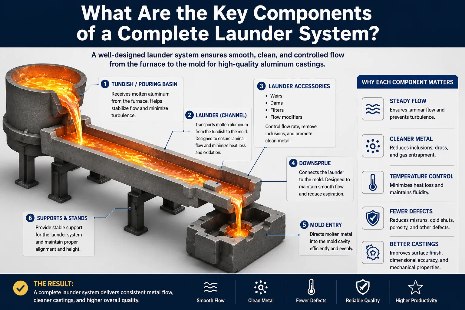
What Are the Key Components of a Complete Launder System?
Understanding the individual components helps both engineers and buyers evaluate system completeness and avoid procurement gaps.
| Component | Function | Material Options | Service Interval |
|---|---|---|---|
| Structural Shell | Mechanical housing and support | Mild steel, 304SS | 15–20 years |
| Primary Refractory Lining | Melt containment and chemical resistance | Fused silica, SiC castable | 8–12 years |
| Backup Insulation Layer | Heat retention | Calcium silicate, ceramic fiber | 5–8 years |
| Resistance Heating Elements | Temperature maintenance | SiC rods, MoSi2 elements, gas burners | 2–5 years |
| Thermocouple Assemblies | Temperature monitoring | Type K, Type N thermocouples | 1–3 years |
| Launder Cover/Lid System | Oxidation reduction, heat retention | Cast iron, ceramic fiber board | 3–8 years |
| Transition Spouts | Furnace-to-launder and launder-to-mold connections | Fused silica, graphite | 1–3 years |
| Drain Plugs and Gates | Flow control and maintenance drainage | Graphite, SiC | 2–5 years |
| Monitoring and Control Panel | Temperature regulation and alarm management | PLC-based industrial controller | 10–15 years |
| Expansion Joints | Thermal movement accommodation | Ceramic fiber rope, castable | 3–6 years |
How Do Thermal Insulation and Heating Technologies Work in Launder Systems?
Passive Insulation vs. Active Heating: When to Choose Each
Passive insulation relies on low-conductivity backup layers to slow heat loss. This approach works well for transfer distances below 8 meters and where melt flow rates are high enough to maintain temperature through the heat content of the metal itself. A launder moving 5 tonnes per hour over 5 meters with well-designed fused silica lining and calcium silicate backup can often maintain temperature within ±10°C without any external heating.
Active heating becomes necessary when:
- Transfer distance exceeds 8–10 meters.
- Flow rates are variable or include periods of low flow.
- Alloy liquidus temperature is above 720°C.
- Ambient temperature drops below 5°C seasonally.
- Temperature uniformity tighter than ±8°C is required.
Electric Resistance Heating in Aluminum Launders
Electric resistance heating uses silicon carbide (SiC) rods or molybdenum disilicide (MoSi2) elements mounted above or alongside the melt channel. SiC elements are more commonly used in aluminum applications because they operate effectively at the temperature range of 700–900°C and are relatively tolerant of the moisture-laden atmospheres present during launder startup.
A typical heated launder section of 2 meters length requires 6–12 kW of installed electrical power to compensate for heat losses and maintain melt temperature. Our control systems use PID (Proportional-Integral-Derivative) algorithms to modulate heater output based on thermocouple feedback, achieving ±3°C temperature control in most applications.
Gas-Fired Launder Heating
For facilities with abundant natural gas supply and limited electrical capacity, gas-fired launder heating uses radiant burners positioned above the launder channel. Gas-fired systems typically have higher peak heating capacity than electric systems, making them suitable for applications requiring rapid temperature recovery after a cold start or after a production interruption.
The trade-off is that gas combustion introduces combustion products above the melt surface. In applications where hydrogen absorption is a concern, combustion atmosphere management becomes an additional engineering challenge.
What Industry Standards and Certifications Govern Aluminum Launder Design?
Compliance with recognized standards is not optional for reputable aluminum producers. Buyers should verify that any launder manufacturer can demonstrate conformance with the following frameworks:
| Standard / Specification | Scope | Relevance to Launder Systems |
|---|---|---|
| ISO 9001:2015 | Quality Management Systems | Manufacturing quality control |
| ASTM C401 | Classification of Alumina Refractories | Lining material classification |
| ASTM C862 | Practice for Preparing Refractory Castable Specimens | Curing and testing procedures |
| EN 1092-1 | Flanges and Their Joints | Flange design for modular connections |
| NFPA 86 | Standard for Ovens and Furnaces | Safety requirements for heated systems |
| IEC 60079 | Explosive Atmospheres | Electrical system safety near molten metal |
| Aluminum Association Standards | Alloy and process specifications | Alloy-specific material compatibility |
AdTech maintains ISO 9001:2015 certification and designs launder systems to comply with NFPA 86 requirements for heated enclosures and IEC 60079 for electrical installations in hazardous areas adjacent to molten metal operations.
How Do You Select the Right Launder Configuration for Your Foundry Layout?
Configuration selection involves matching the physical constraints of your facility to the hydraulic and thermal requirements of your production process. The following decision framework summarizes the key selection factors:
Launder Configuration Selection Matrix
| Facility Condition | Recommended Configuration | Key Design Feature |
|---|---|---|
| Short transfer (< 5 m), high flow rate | Passive insulated straight launder | Thick fused silica lining, calcium silicate backup |
| Long transfer (> 15 m), variable flow | Electrically heated modular launder | PID temperature control, SiC heating elements |
| Complex routing with elevation changes | Multi-section curved launder with transition spouts | CFD-optimized bends, zero dead zones |
| Inline degassing required | Degassing launder with rotary impeller housing | Integrated impeller port, sealed cover system |
| Multi-strand casting machine | Tundish distribution launder | Even flow distribution to each strand |
| High-purity alloy production | Filtered launder with ceramic foam filter box | Integral filter housing, pressure drop monitoring |
| Outdoor or cold-climate installation | Fully enclosed heated launder with thermal blanket | Enhanced insulation, frost protection heating |
We strongly advise against selecting launder configuration based on catalog descriptions alone. Our experience shows that production conditions at two seemingly identical facilities can require fundamentally different launder designs due to differences in casting rhythm, alloy mix, and operator practices.
What Is the Total Cost of Ownership for a Custom Aluminum Launder System?
Procurement teams frequently compare launder systems on initial purchase price, which is a poor basis for decision-making. The total cost of ownership (TCO) over a 10-year operating period reveals a very different picture.
10-Year TCO Breakdown: AdTech Heated Launder vs. Generic Supplier
| Cost Category | AdTech Launder | Generic Supplier Launder |
|---|---|---|
| Initial Purchase Price | $85,000–$120,000 | $45,000–$65,000 |
| Installation and Commissioning | $12,000–$18,000 | $10,000–$15,000 |
| Refractory Reline (10 years) | 1× reline at year 9–10: $15,000 | 3–4 relines at years 3, 5, 7, 9: $45,000–$60,000 |
| Energy Cost (heating, 10 years) | $28,000–$35,000 | $38,000–$50,000 (less efficient insulation) |
| Maintenance and Parts | $8,000–$12,000 | $18,000–$28,000 |
| Scrap and Defect Losses (reduced) | Baseline | +$40,000–$80,000 in additional scrap |
| Total 10-Year TCO | $148,000–$200,000 | $196,000–$308,000 |
The numbers above are based on actual operational data from clients who transitioned from generic launder suppliers to AdTech systems. The dominant cost saving comes from extended lining life and reduced casting scrap, not from the purchase price difference itself.
How Does AdTech’s Launder System Compare to Competitors in Performance?
We are aware that several suppliers in China, Europe, and North America offer molten aluminum launder systems. Rather than making claims without basis, we present objective performance parameters that buyers can verify through factory trials or third-party audits.
Performance Comparison: Key Metrics
| Performance Metric | AdTech System | Industry Average | Premium European Systems |
|---|---|---|---|
| Temperature uniformity (over 10 m) | ±5°C | ±15°C | ±5–8°C |
| Lining service life | 8–12 years | 3–5 years | 6–10 years |
| Oxide inclusion generation | < 0.5 mg/kg melt | 2–5 mg/kg melt | < 1 mg/kg melt |
| Aluminum absorption by lining | < 0.1% per heat | 0.3–0.8% per heat | < 0.15% per heat |
| Modular delivery time | 6–10 weeks | 10–16 weeks | 12–20 weeks |
| Available customization | Full custom | Limited | Full custom |
| After-sales service response | 24-hour | Varies | 48–72 hour |
The oxide inclusion generation data is particularly significant because oxide inclusions are directly linked to casting defect rates. Our launder geometry design, lining surface quality, and cover system design work together to minimize melt surface disturbance and atmospheric exposure.
What Are Common Failure Modes and How Are They Prevented?
Understanding failure modes is essential for both engineers designing maintenance schedules and procurement managers evaluating supplier quality.
Failure Mode Analysis for Aluminum Launder Systems
| Failure Mode | Root Cause | Prevention Method | Detection Method |
|---|---|---|---|
| Refractory cracking | Thermal shock during startup, improper curing | Controlled heat-up protocol, correct material selection | Visual inspection, thermocouple anomaly |
| Aluminum penetration into lining | Cracks, porous lining, chemical attack | High-density fused silica, non-wetting coatings | Post-campaign core sample analysis |
| Heater element burnout | Overtemperature, mechanical damage, moisture | Proper curing, element rating selection | Resistance monitoring, visual check |
| Oxide buildup at bends | Turbulent flow, dead zones | CFD-optimized geometry, regular cleaning | Flow monitoring, visual inspection |
| Shell distortion | Excessive heat loss through joints, inadequate support | Proper expansion joint design, structural analysis | Dimensional survey |
| Thermocouple drift | Contamination, aging | Calibration schedule, protective sheathing | Cross-reference between multiple sensors |
| Leakage at joints | Improper sealing, thermal cycling damage | Ceramic rope gaskets, proper bolt torque | Visual inspection, metal detector under launder |
We recommend a quarterly maintenance inspection protocol that covers all failure modes listed above. Our service team provides clients with a structured inspection checklist and, for larger installations, offers annual service contracts that include thermocouple recalibration, joint resealing, and lining condition assessment.
How Is a Molten Aluminum Launder System Installed and Commissioned?
Pre-Installation Requirements
Before our installation team arrives on site, the following conditions must be in place:
- Civil foundation work completed and cured (concrete at 28-day strength).
- Furnace tap-hole at final height with mounting bracket welded.
- Electrical service run to within 2 meters of launder position.
- Gas supply (if applicable) run to within 1 meter of launder position.
- Crane or forklift with minimum rated capacity of 2 tonnes available.
- Safe work area cleared and barricaded.
- Client operations supervisor available for process coordination.
Step-by-Step Installation Sequence
Step 1: Positioning and leveling — Individual launder sections are set on pre-surveyed support brackets and leveled to within 0.5 mm/meter using precision shims.
Step 2: Section joining — Flange connections are made with ceramic fiber rope gaskets compressed to the specified torque values. This step is critical: under-torqued joints leak; over-torqued joints crack the refractory.
Step 3: Cover system installation — Launder lids or covers are positioned and their lifting/hinged mechanisms are tested for smooth operation.
Step 4: Electrical connection — Heating element leads, thermocouple extension cables, and control panel wiring are connected and continuity-verified before any power is applied.
Step 5: First dry-out cycle — The launder is heated from ambient temperature to 150°C and held for 8 hours, then to 300°C for 8 hours, then to 600°C for 12 hours, and finally to 750°C for 4 hours. Temperature hold at each stage allows moisture and chemically bound water to escape gradually without creating steam pressure that could fracture the lining.
Step 6: First metal trial — The first charge of molten aluminum through a newly commissioned launder should be conducted at a reduced flow rate with the full operations team present. Our commissioning engineer monitors thermocouple readings, visually inspects the launder outlet for signs of turbulence or cold metal, and verifies control system response.
Frequently Asked Questions (FAQs)
1. What is the minimum order quantity for a custom aluminum launder system from AdTech?
AdTech does not impose a minimum order quantity restriction on custom launder systems. Whether you need a single 2-meter transition spout or a complete 40-meter heated launder network, we engineer each project individually. Our minimum project scope for the full engineering design, fabrication, and commissioning service is one complete launder run connecting a furnace to a casting or degassing unit. Clients purchasing only replacement lining kits or spare heating elements do not face minimum quantity restrictions. Contact our sales engineering team with your process parameters, and we will provide a project-specific quotation within 5 business days.
2. How long does a custom launder system take from order placement to delivery?
For a standard heated launder system of 10–20 meters total length, our typical lead time from order confirmation to factory-ready delivery is 8–12 weeks. This includes 2 weeks for detailed engineering finalization, 4–6 weeks for shell fabrication and refractory installation, and 2 weeks for quality control inspection and pre-shipment testing. Highly complex multi-section systems with integrated degassing or filtration modules may require 14–18 weeks. We recommend initiating the engineering phase before formal order placement to compress the overall project schedule, particularly for clients with production startup deadlines.
3. Can AdTech launder systems handle all aluminum alloys, including high-magnesium and high-silicon variants?
Yes, but material specification must reflect the specific alloy chemistry. High-magnesium alloys (Mg content > 3%) present aggressive chemical attack on conventional fused silica lining because magnesium reacts with silica at operating temperatures, forming magnesium silicate compounds that degrade the lining surface. For high-magnesium alloys such as 5182 or 5083, we specify calcium aluminate or alumina-spinel castable linings instead of fused silica. High-silicon alloys (Si > 12%) are generally compatible with fused silica lining. We request full alloy composition data before finalizing any lining specification for a new client.
4. What thermocouple types are used in AdTech launder temperature monitoring systems?
We use Type K thermocouples (chromel-alumel) for applications up to 750°C and Type N thermocouples (nicrosil-nisil) for applications where long-term accuracy is prioritized or where temperatures intermittently reach 850°C. Type N thermocouples exhibit superior drift resistance compared to Type K at elevated temperatures, making them the preferred choice for heated launder applications where calibration interval is more than 6 months. All thermocouples are supplied with mineral-insulated (MI) cable construction and ceramic protection tubes to resist the corrosive atmosphere near molten aluminum. Our standard monitoring panel logs thermocouple data at 1-minute intervals with alarm setpoints programmable by the client.
5. How do you calculate the required launder slope for reliable gravity flow?
The slope calculation requires three primary inputs: melt flow rate (kg/min), channel cross-section area, and melt viscosity (approximately 1.2 mPa·s for most aluminum alloys at 720°C). Using the Manning equation adapted for non-Newtonian behavior corrections, our hydraulic models target a flow velocity of 0.2–0.4 m/s. This velocity range maintains smooth laminar-to-transitional flow while preventing both dead zones (velocity < 0.1 m/s leads to freeze-up risks) and turbulent conditions (velocity > 0.5 m/s generates oxide entrainment). Typical calculated slopes range from 1° to 3°, with the specific value depending on channel width and depth. We do not recommend using rule-of-thumb slopes without completing a hydraulic calculation.
6. What is the best way to clean a launder between production campaigns?
The most effective launder cleaning procedure involves draining residual aluminum through the drain plug while the launder is still at operating temperature, then using a dry refractory scraper tool to remove any freeze skull while the lining is still above 200°C. Never apply water or water-based cleaning agents to a hot launder. Allow the launder to cool to below 80°C before any wet cleaning or inspection work. For stubborn skull buildup at bends or transition points, a mild pneumatic chipping tool can be used with caution to avoid damaging the primary lining surface. We recommend full interior visual inspection at each major campaign break and photographic documentation for trending over time.
7. Can the AdTech launder system be integrated with an existing degassing unit or online filtration box?
Integration with degassing units such as rotary impeller degassers and with ceramic foam filtration boxes is a standard feature of our modular launder design. We design transition sections that connect the launder outlet to the degassing unit inlet without creating dead zones or turbulence. For ceramic foam filtration, we supply integrated filter box housings that are precast with the same fused silica lining as the launder channel. The filter box is sized to accommodate 30, 40, 50, or 60 pore per inch (PPI) foam filters depending on the inclusion removal target. Our engineering team coordinates dimensional interfaces with the degassing unit manufacturer’s specifications.
8. What safety systems are required for a heated aluminum launder installation?
NFPA 86 and local safety regulations typically require the following systems for heated aluminum launders: (1) High-temperature overtemperature cutout switches that de-energize heating elements if the thermocouple reading exceeds the setpoint by more than 30°C; (2) Emergency power cutoff accessible from two locations, one at the launder and one at the main control panel; (3) Molten metal detection sensors below the launder to alarm in case of any lining breach; (4) Interlocks that prevent heating element activation until the launder has completed the dry-out curing protocol; (5) Fire-resistant cable insulation for all wiring within 500 mm of the launder shell exterior. We design all electrical systems to IEC 60364 and provide full electrical schematic documentation for client review by their safety officer.
9. How does AdTech support clients in countries without a local service presence?
Our international service model uses a combination of digital remote support and trained local service partner networks in regions where we do not maintain permanent offices. For commissioning support, our engineers travel to the installation site regardless of location. Post-commissioning, we provide 24/7 remote monitoring support via our cloud-connected control panel option, which transmits thermocouple data and alarm status to our engineering team in real time. We have successfully supported launder installations in Southeast Asia, the Middle East, Africa, and South America through this model. Spare parts are maintained in bonded warehouses in strategic locations to ensure delivery within 5–7 working days to most destinations.
10. What documentation is provided with an AdTech custom launder system?
Every AdTech launder system is delivered with a complete documentation package that includes: (1) Full mechanical assembly drawings in PDF and DXF format; (2) Electrical schematic and wiring diagrams; (3) Refractory material data sheets and compliance certificates; (4) First heat-up and dry-out protocol document; (5) Operating and maintenance manual in the client’s requested language; (6) Spare parts list with AdTech part numbers; (7) Quality control inspection report with test data from factory; (8) ISO 9001:2015 certificate of conformance; (9) Packing list and shipping documents. We also provide a digital version of all documentation through our client portal, which remains accessible throughout the launder’s service life.
Summary: Why AdTech’s Custom Launder Engineering Matters
The molten aluminum transfer launder system is not a commodity product. Its performance directly determines melt quality, casting productivity, and the total cost of your aluminum production operation. At AdTech, we bring together materials science expertise, computational engineering tools, and more than a decade of field installation experience to design launder systems that consistently outperform industry benchmarks.
Our clients who have transitioned from lower-specification launder systems report reductions in casting scrap rates of 15–40%, extension of lining service intervals from 3 years to 8+ years, and improvement in temperature uniformity that directly supports tighter casting tolerances. These are not theoretical projections. They are documented outcomes from operational aluminum plants across four continents.
If you are evaluating launder options for a new casting line, upgrading an existing installation, or troubleshooting recurring melt quality problems, we encourage you to contact our engineering team with your process parameters. We provide a no-obligation preliminary engineering assessment that identifies the most critical design factors for your application.
