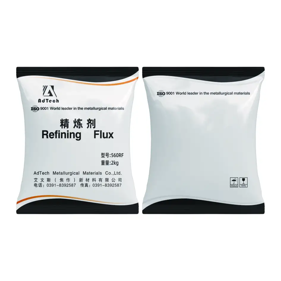
When melting aluminum, the correct flux depends on your specific metallurgical objective: use degassing flux (KCl-NaCl-fluoride granular formulations) to remove dissolved hydrogen and prevent casting porosity, apply drossing flux (powder-form chloride-fluoride salts) to separate and recover metallic aluminum trapped in surface dross, specify covering flux (granular KCl-NaCl mixtures) to protect the melt surface from atmospheric oxidation during holding periods, and choose refining flux (fine powder chloride-fluoride blends) to coagulate and float fine non-metallic inclusions — with AdTech’s complete aluminum flux product range covering all four functions in formulations optimized for temperatures of 680–780°C across automotive die casting, foundry gravity casting, secondary aluminum smelting, and continuous casting operations.
If your project requires the use of Aluminum Fluxes, you can contact us for a free quote.
At AdTech, we field this question constantly from foundry metallurgists, plant managers at secondary smelters, and engineers setting up new aluminum casting lines. The difficulty is that “what flux to use when melting aluminum” is not one question — it is four or five different questions depending on what problem you are trying to solve. We have seen foundries applying drossing flux when their real problem was dissolved hydrogen porosity, and operations spending heavily on premium refining flux when their fundamental issue was moisture in the charge material. Selecting the wrong flux type wastes money and fails to address the actual metallurgical problem.
Why Aluminum Needs Flux Treatment: The Core Metallurgical Problems
Before selecting a flux, understanding precisely why aluminum melt treatment is necessary prevents the common mistake of treating symptoms rather than root causes.
Dissolved Hydrogen: The Porosity Problem
Molten aluminum absorbs hydrogen from multiple sources — atmospheric moisture, wet charge materials, humid furnace gases, and contaminated scrap. The solubility of hydrogen in aluminum drops dramatically at solidification: liquid aluminum at 660°C holds approximately 0.69 ml H₂ per 100g, while solid aluminum at the same temperature holds only 0.036 ml/100g. This 20-fold solubility drop forces dissolved hydrogen to nucleate as gas bubbles during solidification, creating porosity in the finished casting.
The acceptable hydrogen content for most structural aluminum castings is below 0.10–0.15 ml H₂ per 100g Al. Secondary aluminum (recycled scrap) routinely contains 0.30–0.60 ml/100g before treatment — three to six times the acceptable level. Degassing flux addresses this specific problem.
Dross and Metal Loss: The Yield Problem
Every time molten aluminum contacts air, a surface oxide film forms instantly. Turbulence during melting, charging, and stirring folds these films into the melt body and accumulates them as dross on the melt surface. In secondary aluminum operations, dross generation commonly represents 3–8% of total charge weight, with metallic aluminum comprising 40–70% of that dross mass — representing direct revenue loss. Drossing flux addresses this yield problem.
Surface Reoxidation: The Contamination Problem
Between treatment cycles and during holding periods before casting, exposed aluminum melt surfaces continuously form new oxide. Each new oxide layer that forms on the melt surface and is subsequently disturbed creates new bifilm inclusions. Covering flux prevents this reoxidation.
Fine Inclusions and Alkali Metals: The Quality Problem
Even after effective degassing and drossing, aluminum melts contain fine oxide bifilms, spinel particles, and dissolved alkali metals (sodium, calcium, potassium from scrap contamination) that degrade casting mechanical properties. Sodium content above approximately 15 ppm in aluminum-silicon alloys causes eutectic modification to become excessive and can cause hydrogen absorption to accelerate. Refining flux removes these fine contaminants.
The Four Main Types of Aluminum Melting Flux and What Each Does
Quick Reference: Flux Type vs. Problem Solved
| Flux Type | Primary Problem Solved | Secondary Benefit | Physical Form | When Applied |
|---|---|---|---|---|
| Degassing flux | Dissolved hydrogen / porosity | Some inclusion flotation | Granular powder | During or after complete melt |
| Drossing flux | Dross metal loss / surface oxide | Cleaner skim line | Fine powder | When dross accumulates |
| Covering flux | Surface reoxidation during holding | H₂ absorption barrier | Coarse granular | After skimming / during holding |
| Refining flux | Fine inclusions / alkali metals | Grain refinement support | Fine powder | Before casting, after degassing |
| Multipurpose flux | Combined functions | Simplified treatment | Granular powder | General treatment |
| Furnace cleaning flux | Wall / hearth oxide buildup | Metal recovery from buildup | Coarse granular | Maintenance periods |
Understanding When You Need Each Type
The four-question diagnostic we use with new foundry clients:
Are you seeing gas porosity or sponge porosity in castings? → Primary need is degassing flux, combined with rotary degassing equipment if porosity is severe.
Is your aluminum metal recovery below 93–95%? → Primary need is drossing flux to reduce metal trapped in surface oxide.
Is your casting hydrogen content rising during long holding periods? → Primary need is covering flux to prevent atmospheric hydrogen absorption during holding.
Are you seeing mechanical property scatter, elongation shortfalls, or machined surface inclusions? → Primary need is refining flux to remove fine bifilm inclusions and alkali contamination.
Many operations have multiple problems simultaneously — in these cases, a treatment sequence using dedicated fluxes in the correct order outperforms any single multipurpose product.
Degassing Flux: When to Use It, How It Works, and Correct Dosing
The Mechanism of Hydrogen Removal
Degassing flux works through a physical bubble-transport mechanism rather than direct chemical reaction with hydrogen. When flux granules or powder contact molten aluminum, chloride salt components react with trace moisture and aluminum to generate very fine gas bubbles — primarily chlorine gas (Cl₂) and chloride vapors. These bubbles rise through the melt.
As each rising bubble passes through the aluminum, dissolved hydrogen diffuses from the surrounding metal into the bubble interior, driven by the concentration gradient between the hydrogen-saturated metal and the essentially hydrogen-free bubble. The bubble carries this hydrogen to the melt surface where it escapes to the atmosphere.
The process efficiency depends critically on bubble size (smaller bubbles have dramatically higher surface area per unit volume and collect more hydrogen) and bubble distribution (uniform distribution throughout the melt depth removes hydrogen from all zones, not just near the lance or injection point). This explains why rotary degassing units — which produce bubbles 2–5mm diameter distributed uniformly — outperform lance injection significantly.
When to Specify Degassing Flux
Degassing flux is the correct choice when:
- Casting porosity is the primary quality problem.
- Density Index (DI) measurements exceed 4–5% before treatment.
- Hydrogen content measurement exceeds 0.15 ml/100g Al.
- The operation uses secondary aluminum (recycled scrap) as the primary feedstock.
- Production has experienced recent increases in scrap due to porosity.
- Castings are failing pressure testing or X-ray porosity inspection.
Degassing Flux Specifications
| Parameter | Standard Degassing Flux | Premium Degassing Flux | Test Method |
|---|---|---|---|
| KCl content | 40–50% | 38–45% | XRF analysis |
| NaCl content | 22–32% | 20–30% | XRF analysis |
| Na₃AlF₆ (cryolite) | 15–22% | 16–22% | XRF analysis |
| K₂TiF₆ (in premium) | None | 8–14% | XRF analysis |
| Moisture content | ≤ 0.30% | ≤ 0.20% | Karl Fischer |
| Particle size | 0.5–2.5mm | 0.5–2.0mm | Sieve analysis |
| Melting point range | 650–720°C | 640–710°C | DSC |
| Application temperature | 700–750°C | 700–745°C | Thermocouple |
Degassing Flux Dosing Guidelines
| Application Method | Flux Dose (kg/ton Al) | Carrier Gas | Treatment Time | H₂ Reduction |
|---|---|---|---|---|
| Surface spread + stirring | 3.0–5.0 | None | 10–20 min | 20–35% |
| Flux tablet plunging | 2.0–4.0 | None | 8–15 min | 30–50% |
| Lance injection | 1.5–3.0 | N₂: 5–10 L/min/ton | 10–18 min | 45–65% |
| Rotary degassing unit | 0.8–1.8 | N₂: 4–8 L/min/ton | 12–18 min | 60–80% |
| Rotary + flux combined | 0.5–1.5 | N₂/Ar: 4–7 L/min/ton | 12–20 min | 70–90% |
How to Verify Degassing Effectiveness
The Density Index (DI) test is the most accessible field verification method:
- Take two small metal samples simultaneously from the treated melt.
- Solidify one at atmospheric pressure, one under vacuum (80–100 mbar)
- Weigh both samples precisely.
- Calculate: DI (%) = (ρ_atm − ρ_vac) / ρ_atm × 100.
- Acceptable DI for most casting: below 3–5%; for critical parts: below 1–2%.
A well-executed rotary degassing treatment using quality degassing flux should reduce DI from 10–20% (typical untreated secondary aluminum) to 1–4%.
Drossing Flux: Recovering Metal from Surface Oxide and Reducing Losses
What Dross Actually Contains
Understanding dross composition explains why drossing flux works and why the economics of dross treatment are so compelling:
| Dross Component | Typical Content | Notes |
|---|---|---|
| Metallic aluminum (trapped) | 40–70% | Primary recovery target |
| Aluminum oxide (Al₂O₃) | 15–35% | Non-recoverable |
| Aluminum nitride (AlN) | 5–15% | Forms from N₂ atmosphere contact |
| Magnesium oxide (MgO) | 1–8% | Higher in Mg-bearing alloys |
| Spinels (MgAl₂O₄) | 2–6% | From Mg alloy surface oxidation |
| Salt flux residue | 2–8% | From previous treatments |
The metallic aluminum content represents recoverable revenue. In a foundry melting 500 tons per month with 3% dross generation and 55% metal content in dross (typical untreated baseline), the trapped metal is approximately 8.25 tons/month. At USD 2,500/ton aluminum value, that is over USD 20,000/month in potential metal recovery — the economics for drossing flux investment are immediate.
How Drossing Flux Works
Drossing flux acts on the dross layer through two mechanisms:
Viscosity reduction: The chloride-fluoride salts dissolve into the oxide matrix of the dross, reducing its melting point and viscosity. Liquid metal droplets trapped within the dross structure can then coalesce and drain back into the melt under gravity. The treated dross becomes dry, crumbly, and non-adhesive — easy to skim cleanly.
Surface tension modification: Flux components reduce the interfacial tension between metallic aluminum and aluminum oxide, allowing the oxide skin to release its trapped metal content more readily.
Untreated dross is wet, sticky, and tears metal from the melt surface during skimming. Flux-treated dross is dry and separates cleanly, leaving a bright metal surface behind.
Drossing Flux Specifications
| Parameter | Standard Drossing Flux | Heavy-Duty (Secondary Al) |
|---|---|---|
| KCl content | 52–62% | 48–58% |
| NaCl content | 18–26% | 16–24% |
| Na₃AlF₆ content | 12–18% | 14–20% |
| KF content | 5–12% | 8–16% |
| Moisture | ≤ 0.30% | ≤ 0.25% |
| Particle form | Powder 0.1–0.5mm | Granular 0.5–2.0mm |
| Dosing rate | 5–12 kg/ton dross | 8–18 kg/ton dross |
| Metal recovery improvement | 15–30% vs. no flux | 20–40% vs. no flux |
Correct Drossing Procedure
- Let dross accumulate naturally — do not stir it back into the melt prematurely.
- Reduce melt agitation and allow the surface to calm.
- Apply drossing flux powder uniformly across the entire dross surface.
- Work the flux into the dross body using a perforated skimmer — the flux must penetrate into the dross interior, not just coat the surface.
- Allow 3–5 minutes contact time for the flux to react.
- Skim the treated dross in a single smooth motion from one side of the furnace to the other.
- Inspect the melt surface — it should be bright and clean, not gray or dull.

Covering Flux: Protecting the Melt During Holding and Transfer
The Hydrogen Reabsorption Problem During Holding
After effective degassing treatment, cleaned aluminum reabsorbs hydrogen from furnace atmosphere at a rate of 0.03–0.08 ml H₂ per 100g Al per hour in an unprotected gas-fired furnace. A 4-hour holding period without surface protection can raise hydrogen content from the post-treatment target of 0.10 ml/100g back up to 0.30–0.40 ml/100g — requiring re-treatment before casting.
Covering flux floats on the metal surface as a molten salt blanket, physically preventing atmospheric contact and dramatically slowing hydrogen reabsorption to approximately 0.005–0.020 ml H₂ per 100g Al per hour — a 4–8× reduction.
When to Use Covering Flux
Covering flux is particularly valuable in:
- Operations with batch casting that involve significant holding time between treatment and casting.
- Overnight or shift-change holding of metal in holding furnaces.
- Low-pressure casting operations with sealed holding furnace designs.
- Any operation where re-degassing before every casting cycle is costly or impractical.
- Transfer operations where metal moves between furnaces through open launders.
Covering Flux Specifications
| Parameter | Specification | Notes |
|---|---|---|
| KCl content | 62–75% | Primary carrier phase |
| NaCl content | 20–30% | Eutectic adjustment |
| Na₃AlF₆ content | 5–12% | Oxide dissolution |
| Moisture content | ≤ 0.30% | Critical — wet covering flux absorbs H₂ |
| Particle size | 2–8mm granular | Coarse for spreading and layer formation |
| Melting point | 640–680°C | Must melt and flow at Al holding temps |
| Flux density | 1.6–1.9 g/cm³ | Must be less dense than Al (2.7 g/cm³) |
| Application rate | 5–10 kg/m² melt surface | Sufficient for continuous coverage |
| Layer thickness | 15–30mm effective | Thinner layers allow atmospheric contact |
Refining Flux: Removing Fine Inclusions and Alkali Metals
Why Standard Degassing and Drossing Leave Residual Problems
Even after thorough degassing and drossing treatment, a residual population of fine inclusions remains in the melt:
- Sub-millimeter oxide bifilm fragments too light to skim and too fine for bubble flotation.
- Spinel (MgAl₂O₄) particles that resist standard treatment.
- Dissolved alkali metals (Na, Ca, K) from scrap contamination that cannot be removed by hydrogen bubble flotation.
Sodium contamination above approximately 10–15 ppm in Al-Si alloys causes eutectic over-modification, reduces elongation, and accelerates hydrogen absorption. Calcium above 5–8 ppm has similar effects. These alkali metals require specific fluoride chemistry to form removable compound salts.
How Refining Flux Addresses Fine Inclusions
Refining flux works through two additional mechanisms beyond standard degassing and drossing chemistry:
Inclusion coagulation: Fine fluoride components in refining flux reduce the surface tension of fine oxide particles, promoting their agglomeration into larger clusters that are more easily removed by flotation. This is the mechanism that makes refining flux particularly effective at improving elongation and fatigue life in automotive aluminum castings.
Alkali metal extraction: Fluoride components (particularly KF and Na₂SiF₆) react with dissolved sodium and calcium in the melt to form complex fluoride compounds (NaAlF₄, Ca₂AlF₇) that are insoluble in aluminum and float to the dross layer for removal. This chemistry can reduce sodium content from 30–80 ppm (typical contaminated secondary scrap) to below 10 ppm after thorough refining flux treatment.
Refining Flux Specifications
| Parameter | Standard Refining Flux | Premium Refining Flux |
|---|---|---|
| KCl content | 38–48% | 35–45% |
| NaCl content | 18–26% | 16–24% |
| Na₃AlF₆ content | 20–28% | 22–30% |
| KF content | 10–16% | 12–18% |
| Na₂SiF₆ | None | 3–6% |
| Particle form | Powder 0.1–0.3mm | Fine powder 0.05–0.2mm |
| Dosing rate | 1.5–3.0 kg/ton Al | 1.0–2.5 kg/ton Al |
| Na reduction | 40–65% | 55–75% |
| Application method | Injection / tablet | Injection preferred |
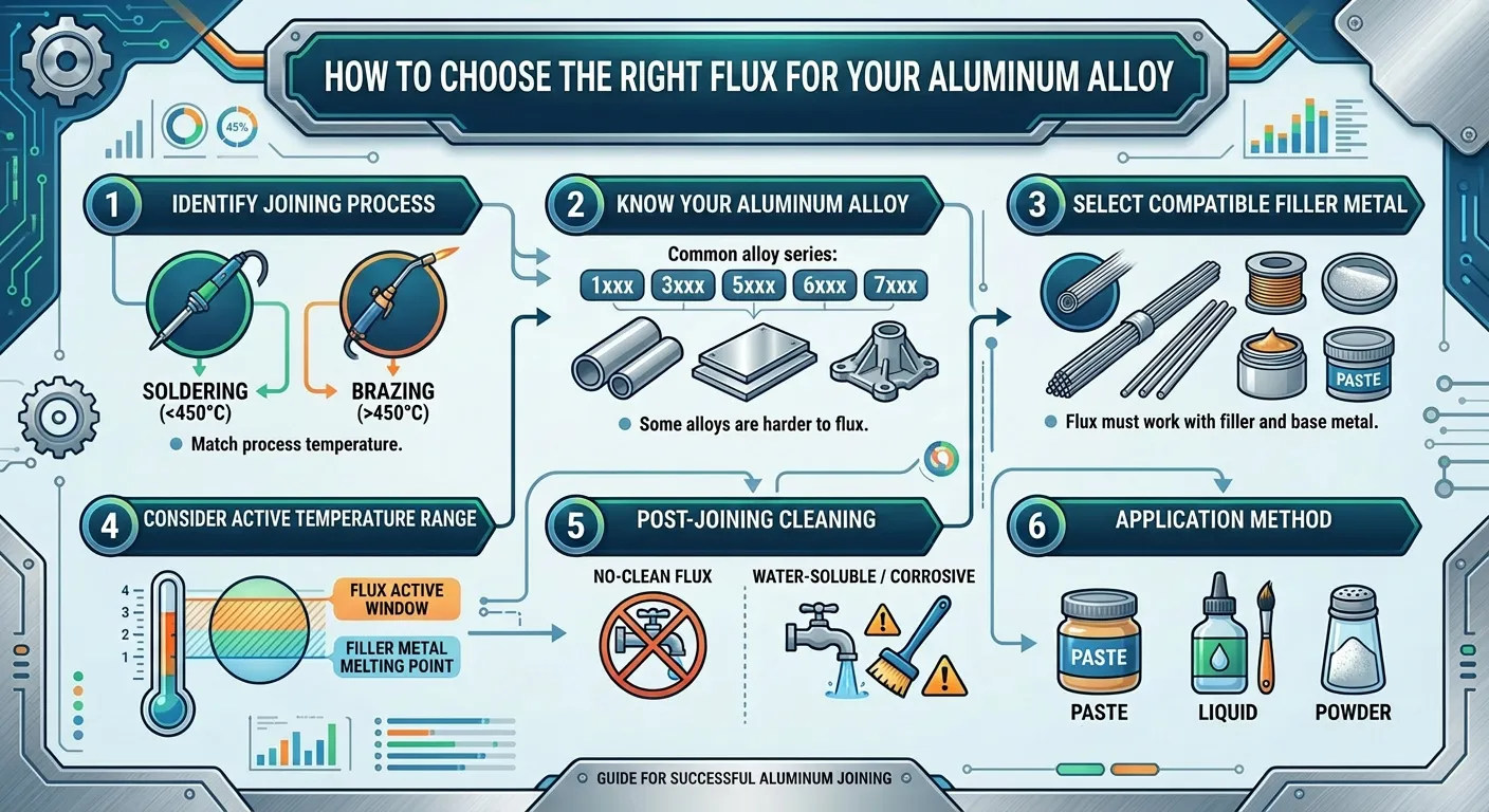
How to Choose the Right Flux for Your Aluminum Alloy
Alloy-Specific Flux Selection Table
| Alloy Type | Primary Challenge | Recommended Flux | Secondary Flux | Special Consideration |
|---|---|---|---|---|
| A356 / A357 (Al-Si-Mg) | H₂ porosity + spinel | DG flux + RF refining | CV covering | Mg increases dross rate; use heavy drossing |
| A380 / ADC12 (Al-Si-Cu) | H₂ + secondary scrap inclusions | DG flux + DR drossing | CV covering | High volume; cost-sensitive; multipurpose viable |
| 319 (Al-Si-Cu) | Copper inclusion management | DG flux + DR drossing | RF refining | Cu intermetallics can block filters |
| A413 / LM6 (Al-Si eutectic) | Moderate H₂; surface oxide | DG flux + DR drossing | CV covering | Standard treatment; responsive to flux |
| 2xx.x (Al-Cu) | High H₂ at elevated temp | DG flux (high dose) + CV | RF refining | Treat at 730–750°C; copper sensitivity |
| 5xx.x (Al-Mg, >3% Mg) | Very aggressive oxidation | DR heavy-duty + DG flux | CV covering | Mg content doubles dross generation rate |
| 7xx.x (Al-Zn-Mg) | Complex inclusions + Zn | DG flux + RF refining | CV covering | Zinc fume; ventilation critical |
| Secondary / recycled alloys | High H₂ + high inclusion load | DG + DR + RF combined | CV covering | Most demanding treatment requirement |
| 1xxx high-purity Al | Minimal inclusions; H₂ | DG flux (low dose) | CV covering | Very clean; fine PPI filtration downstream |
Secondary vs. Primary Aluminum: Why Treatment Intensity Differs
This is one of the most important distinctions in flux selection that many guides overlook. Primary aluminum (produced from alumina by electrolysis) arrives at the foundry with low hydrogen content (typically 0.05–0.15 ml/100g) and minimal oxide inclusion load. Secondary aluminum (recycled scrap) carries:
- 3–6× higher dissolved hydrogen content.
- 5–10× higher oxide inclusion population.
- Potential alkali metal contamination from scrap coatings and lubricants.
- Physical debris from scrap surface contamination.
The correct flux treatment program for secondary aluminum is fundamentally more intensive than for primary aluminum:
| Treatment Parameter | Primary Aluminum | Secondary Aluminum |
|---|---|---|
| Degassing flux dose | 0.5–1.0 kg/ton | 1.2–2.5 kg/ton |
| Drossing frequency | As needed | Every melting cycle |
| Refining flux | Usually not needed | Recommended for automotive quality |
| Rotary degassing | Recommended | Strongly recommended |
| Post-treatment DI target | ≤ 2% | ≤ 4% (≤ 2% for critical parts) |
| Treatment cycle time | 10–15 min | 15–25 min |
Flux Application Methods: From Manual to Rotary Degassing Systems
Why Application Method Matters as Much as Flux Selection
The same flux product delivers dramatically different results depending on how it is applied. This is perhaps the most underappreciated factor in aluminum flux treatment. We have seen foundries using premium flux products and achieving poor results because of inadequate application technique, while other operations achieve excellent results with standard flux products through proper rotary degassing equipment.
Comparative Application Method Performance
| Method | Equipment | H₂ Removal | Flux Efficiency | Capital Investment |
|---|---|---|---|---|
| Surface spread + manual stirring | Steel ladle/skimmer | 20–35% | Low | Minimal |
| Flux tablet/briquette submersion | Bell plunger | 30–50% | Medium-Low | Very Low |
| Lance injection (N₂ carrier) | Lance + gas supply | 45–65% | Medium | Low-Medium |
| Rotary degassing (no flux) | Rotary unit + gas | 55–75% | N/A | Medium-High |
| Rotary degassing + flux injection | Full system | 70–90% | Very High | High |
Manual Application Best Practice
For operations without injection equipment, manual application can achieve meaningful results:
- Verify melt temperature is within 700–740°C range.
- Remove any accumulated dross by skimming before flux application.
- Weigh the correct flux dose precisely — eyeballing leads to under-dosing consistently.
- Distribute flux across the melt surface in sections rather than dumping in one location.
- Using a perforated steel plunger, work the flux below the surface repeatedly across the full melt volume.
- Allow a minimum 8–12 minutes of active treatment before skimming.
- Skim cleanly, then assess surface condition before proceeding to casting.
Rotary Degassing Unit Operation
For operations above 2 tons melt capacity where casting quality matters, rotary degassing is the correct approach. The graphite rotor spinning at 200–500 RPM generates bubbles of 2–5mm diameter — versus 15–40mm from manual lance injection — providing dramatically more surface area for hydrogen collection per cubic meter of gas consumed.
AdTech manufactures graphite rotor and shaft degassing systems optimized for use with our flux products:
Key rotary unit parameters:
- Rotor speed: 300–450 RPM (typical optimal range for most applications)
- Rotor immersion depth: 100–150mm above furnace hearth
- Carrier gas (N₂ or Ar): 4–8 L/min per ton of aluminum being treated
- Treatment duration: 12–18 minutes per ton for secondary aluminum
- Flux injection rate: 0.8–1.5 kg/ton delivered via flux injector unit
Flux Chemistry Explained: What the Ingredients Actually Do
Understanding the function of each chemical component in aluminum flux helps in evaluating supplier products and troubleshooting treatment problems.
Component Function Reference Table
| Chemical Component | Chemical Formula | Function in Flux | Typical Content | What Happens Without It |
|---|---|---|---|---|
| Potassium chloride | KCl | Carrier salt; eutectic formation; low melting point | 35–55% | Flux melting point rises; reduced fluidity |
| Sodium chloride | NaCl | Carrier salt; eutectic adjustment | 18–32% | Similar to KCl absence; composition shift |
| Cryolite | Na₃AlF₆ | Dissolves Al₂O₃; reduces oxide film viscosity | 12–25% | Reduced oxide removal; harder dross |
| Potassium fluoride | KF | Aggressive oxide dissolution; alkali metal removal | 5–18% | Less effective alkali removal; harder dross |
| Potassium fluorotitanate | K₂TiF₆ | Nucleation sites for H₂ bubbles; finer bubble generation | 5–14% | Larger bubbles; less efficient degassing |
| Sodium hexafluorosilicate | Na₂SiF₆ | Cleaning agent; wall oxide dissolution | 3–8% | Less effective furnace cleaning flux |
| Calcium fluoride | CaF₂ | Melting point adjuster; supplemental flux | 2–8% | Melting point may rise slightly |
Why Moisture Content Is Critical
Moisture content in flux is the single most critical quality parameter — more important than any active ingredient ratio. Even 0.5% moisture in degassing flux causes:
- Violent steam generation when flux contacts 720°C aluminum (steam pressure exceeds atmospheric instantly at these temperatures)
- Potential molten metal spray creating burn hazard
- HCl gas generation from moisture-chloride reaction before flux reaches optimal treatment temperature
- Reduced degassing efficiency because steam bubbles collect less hydrogen per unit volume than properly generated treatment gas
AdTech specifications require moisture content below 0.30% (0.20% for premium grades) and we ship flux in moisture-proof sealed packaging. Opened containers must be resealed immediately and stored below 60% relative humidity.
Common Flux Treatment Mistakes and How to Avoid Them
The Eleven Most Damaging Errors in Aluminum Flux Practice
Mistake 1: Applying drossing flux when the problem is dissolved hydrogen
Drossing flux treats surface dross; it does not remove dissolved hydrogen. If your problem is gas porosity, specify degassing flux. The diagnostic is simple: if porosity is subsurface and uniform, it is hydrogen-related; if defects are surface oxide-related, drossing flux is relevant.
Mistake 2: Under-dosing to save flux cost
Under-dosing flux saves perhaps USD 0.50–2.00 per ton of metal while achieving 30–40% of potential hydrogen reduction — a false economy when each casting rejection costs USD 10–500. Dose to specification based on actual melt weight.
Mistake 3: Treating at incorrect temperature
Flux treatment below 680°C is ineffective because flux melting point approaches melt temperature, reducing flux fluidity and chemical activity. Treatment above 780°C accelerates reoxidation and hydrogen absorption faster than flux can remove it. Target 710–740°C.
Mistake 4: Using wet or moisture-contaminated flux
Visually identical to dry flux but creates safety hazards, generates excessive fumes, and delivers dramatically inferior metallurgical performance. Check container seals before every use; do not use flux from damaged packaging.
Mistake 5: Skimming before full treatment time
Most foundries underestimate the required treatment duration. Effective degassing requires 12–18 minutes per ton using rotary equipment, not the 4–6 minutes some operators use. Check DI results systematically — they will reveal if treatment is being cut short.
Mistake 6: Treating with existing dross present
Dross on the melt surface before degassing treatment insulates the metal from flux bubble contact in the near-surface zone and absorbs flux preferentially. Always skim dross before degassing treatment begins.
Mistake 7: Ignoring alloy-specific requirements
A flux dose appropriate for primary A356 aluminum is insufficient for secondary ADC12 with high inclusion load. Alloy type and metal source (primary vs. secondary) should drive flux selection and dosing.
Mistake 8: Not following treatment with ceramic foam filtration
Flux treatment removes coarse inclusions and dissolved hydrogen. It cannot remove fine bifilm inclusions — that requires downstream ceramic foam filtration. Operating flux treatment without filtration leaves a residual inclusion population that causes casting defects.
Mistake 9: Allowing re-oxidation between treatment and casting
Treated metal left without covering flux protection reabsorbs hydrogen at 0.03–0.08 ml/100g per hour. Apply covering flux immediately after degassing if casting is not immediate.
Mistake 10: Applying flux to a turbulent melt
Turbulence during flux treatment introduces new oxide films faster than flux removes them. Minimize stirring and agitation during treatment except for deliberate flux distribution movements.
Mistake 11: No measurement before and after treatment
Without DI measurement or other hydrogen assessment, there is no way to know if treatment achieved the target. Implement systematic DI testing as a minimum process control.
AdTech Aluminum Flux Product Range: Specifications and Ordering
AdTech Complete Flux Product Matrix
| Product Code | Flux Type | Main Composition | Form | Dose Rate | Primary Application |
|---|---|---|---|---|---|
| AdTech DG-1 | Degassing flux (premium) | KCl 42%, NaCl 24%, Na₃AlF₆ 20%, K₂TiF₆ 10%, KF 4% | Granular 0.5–2mm | 0.8–1.8 kg/ton | Rotary degassing injection |
| AdTech DG-2 | Degassing flux (standard) | KCl 47%, NaCl 28%, Na₃AlF₆ 18%, KF 7% | Powder 0.1–0.5mm | 1.5–3.0 kg/ton | Lance injection / manual |
| AdTech DR-1 | Drossing flux (standard) | KCl 55%, NaCl 20%, Na₃AlF₆ 15%, KF 10% | Powder 0.1–0.5mm | 5–12 kg/ton dross | Standard foundry dross |
| AdTech DR-2 | Drossing flux (heavy-duty) | KCl 50%, NaCl 17%, Na₃AlF₆ 18%, KF 15% | Granular 0.5–2mm | 8–18 kg/ton dross | Secondary Al; heavy dross |
| AdTech CV-1 | Covering flux | KCl 67%, NaCl 23%, Na₃AlF₆ 10% | Granular 2–8mm | 5–10 kg/m² | Holding furnace protection |
| AdTech RF-1 | Refining flux | KCl 40%, NaCl 20%, Na₃AlF₆ 24%, KF 16% | Fine powder | 1.5–3.0 kg/ton | Automotive; alkali removal |
| AdTech MP-1 | Multipurpose flux | KCl 44%, NaCl 22%, Na₃AlF₆ 20%, KF 14% | Granular 0.5–2mm | 2.0–4.0 kg/ton | General treatment programs |
| AdTech CL-1 | Cleaning flux | Na₃AlF₆ 40%, KF 30%, KCl 30% | Granular 1–4mm | 10–20 kg/m² oxide | Furnace wall / hearth cleaning |
| AdTech LC-1 | Low-chloride flux | Organic salt 50%, fluoride 35%, KCl 15% | Powder | 1.5–2.5 kg/ton | EU / regulated markets |
Minimum Order and Lead Time
AdTech flux products are supplied in 25kg moisture-proof sealed bags, with standard pallet quantities of 1,000kg (40 bags). For trial orders, 5-bag minimums (125kg) are available. Standard lead time from order confirmation is 7–15 business days for stocked formulations. Custom formulations or low-chloride grades require 15–25 business days.
Frequently Asked Questions (FAQs)
Q1: What is the best flux to use when melting aluminum for casting?
The best flux depends on your specific objective. For reducing casting porosity from dissolved hydrogen, specify a degassing flux based on KCl-NaCl-fluoride chemistry applied via lance injection or rotary degassing unit at 1.0–2.0 kg per ton of aluminum. For reducing dross metal loss, use a drossing flux powder applied directly to the dross surface at 5–15 kg per ton of dross. Most production aluminum foundries need both: a degassing treatment to address porosity, followed by drossing flux to skim cleanly and recover maximum metal. For operations that hold metal for extended periods, add covering flux after skimming. AdTech’s DG-1 degassing flux and DR-1 drossing flux are the correct starting specifications for the majority of automotive aluminum casting operations.
Q2: Can I use a single multipurpose flux instead of separate degassing and drossing flux?
Multipurpose fluxes provide convenience and simplified treatment procedures, making them suitable for smaller operations and applications where the quality target is moderate. However, dedicated single-function fluxes consistently outperform multipurpose products because each formulation can be optimized for its specific mechanism — the optimal chemistry for hydrogen bubble nucleation differs from the optimal chemistry for dross viscosity reduction. For automotive safety-critical castings, aerospace components, or any application requiring consistent achievement of DI below 2%, dedicated degassing flux through rotary equipment is strongly recommended over multipurpose alternatives.
Q3: How much degassing flux do I need per ton of aluminum?
Flux dosing depends primarily on your application method. For rotary degassing units: 0.8–1.8 kg of degassing flux per ton of aluminum being treated, combined with nitrogen or argon carrier gas at 4–8 L/min per ton, for 12–18 minutes treatment time. For lance injection without a rotary unit: 1.5–3.0 kg/ton for 10–18 minutes. For manual surface treatment without injection equipment: 3.0–5.0 kg/ton with active stirring for 15–20 minutes. Note that secondary aluminum (recycled scrap) requires the higher end of these ranges due to higher initial hydrogen content and greater inclusion load compared to primary aluminum.
Q4: What happens if I use too much flux when melting aluminum?
Over-dosing degassing or drossing flux beyond approximately 2× the recommended rate has several negative consequences: increased HCl and fluoride gas generation requiring more ventilation, greater volume of flux-contaminated dross requiring disposal, potential for excess flux residue to remain in the melt if not properly skimmed (introducing salt inclusions into castings), and unnecessary cost without additional metallurgical benefit. The response to poor treatment results should be to improve application method (switching to rotary degassing) rather than simply increasing flux dose.
Q5: Should I use nitrogen or argon as the carrier gas for degassing flux injection?
Both nitrogen and argon are effective carrier gases for degassing flux injection. Nitrogen is significantly less expensive (typically 5–10× lower cost than argon) and is appropriate for most aluminum alloys including A356, A380, ADC12, and most commercial casting alloys. Argon is preferred for: magnesium-bearing alloys where nitrogen can form aluminum nitride at the melt surface, high-purity aluminum grades sensitive to nitrogen contamination, and any application where the absolute minimum gas-related inclusions are required. For most commercial foundry operations, nitrogen is the appropriate choice. Use ultra-high-purity grades (99.999%) of either gas to minimize moisture and oxygen contamination.
Q6: How do I know if my flux treatment is actually working?
The most accessible verification is the Density Index (DI) test: solidify one sample at atmospheric pressure and one under vacuum (80–100 mbar), weigh both, and calculate DI = (atm density − vac density) / atm density × 100. Take measurements before and after treatment. A properly executed rotary degassing treatment should reduce DI from 10–20% (typical untreated secondary aluminum) to 1–5%. If post-treatment DI remains above 6–8%, investigate: treatment temperature (check that melt is at 710–740°C), carrier gas flow rate (verify flow meter calibration), flux moisture (test or replace flux), treatment duration (extend if under 12 minutes per ton), and rotor condition (inspect for wear or blockage).
Q7: Can I use table salt (NaCl) as a flux when melting aluminum?
Technically, sodium chloride does provide some metallurgical function in molten aluminum — it is one of the base components in commercial chloride-based flux formulations. However, using table salt alone as a flux is ineffective for several reasons: it lacks the fluoride components (cryolite, KF) that provide the critical oxide dissolution and fine inclusion removal functions, it contains moisture and anti-caking agents that generate excessive HCl fumes, and it lacks the optimized eutectic composition that gives commercial flux products their correct melting point and fluidity at treatment temperature. Table salt also provides no degassing benefit — hydrogen removal requires the specific bubble nucleation chemistry provided by fluoride components. Use properly formulated commercial degassing flux for any application requiring measurable metallurgical improvement.
Q8: What flux should I use for melting aluminum with high magnesium content (like 5xxx alloys)?
High-magnesium aluminum alloys (5xxx series, or any alloy with Mg above 1%) present a more challenging treatment environment. Magnesium oxidizes approximately 1,000× faster than aluminum at melt temperatures, generating dross at a dramatically higher rate. Recommendations: use heavy-duty drossing flux (AdTech DR-2) rather than standard drossing flux, increase the drossing flux application rate by 25–40% compared to standard Al-Si alloys, apply covering flux immediately after each skimming operation to protect the Mg-rich melt surface, and reduce holding time between treatment and casting. For degassing, standard KCl-NaCl-fluoride flux remains appropriate, but consider argon rather than nitrogen as the carrier gas to minimize aluminum nitride formation, which is more problematic with high-Mg alloys.
Q9: How long does treated aluminum remain clean before I need to re-treat it?
Degassed and cleaned aluminum begins reabsorbing hydrogen immediately after treatment ends, at a rate of 0.03–0.08 ml H₂ per 100g Al per hour in an unprotected gas-fired furnace. Without covering flux, hydrogen content can rise from post-treatment levels of 0.10 ml/100g back to 0.25–0.35 ml/100g within 3–4 hours, requiring re-treatment. With covering flux maintaining a protective salt blanket over the melt surface, reabsorption slows to 0.005–0.020 ml/100g per hour, extending the window for clean metal to 6–10 hours before re-treatment becomes necessary. The practical recommendation: for standard castings, treat and cast within 45–60 minutes; for critical applications (aerospace, pressure-tight hydraulic parts), cast within 20–30 minutes of treatment completion, regardless of covering flux application.
Q10: What is the difference between flux used in a rotary degassing unit versus flux used manually?
The same flux formulation can be used in both methods, but the physical form and particle size should be optimized for each. Rotary degassing unit injection requires finer granular flux (0.5–2.0mm particle size) that flows reliably through the flux injector mechanism without bridging or blockage in the feed tubes — AdTech DG-1 is formulated specifically for this application. Manual application (surface spreading or lance injection without a rotary unit) works better with powder form flux (0.1–0.5mm) — AdTech DG-2 is the appropriate formulation. Using coarse granular flux intended for rotary injection in manual surface application reduces effectiveness because large particles sink slowly through the melt rather than distributing rapidly; conversely, fine powder flux can clog rotary injection equipment. Beyond particle size, rotary unit application typically uses 40–60% less flux per ton of aluminum to achieve equivalent or better hydrogen reduction, because the rotor’s bubble-generation efficiency dramatically reduces the amount of flux needed per unit of metallurgical work performed.
Summary: Building a Complete Aluminum Melt Treatment Program
Choosing what flux to use when melting aluminum requires matching flux type precisely to the metallurgical objective you are trying to achieve. The framework is straightforward:
For porosity from dissolved hydrogen: Degassing flux (KCl-NaCl-Na₃AlF₆ system), applied via rotary degassing unit at 0.8–1.8 kg/ton Al with nitrogen carrier gas, targeting post-treatment DI below 3%.
For dross metal loss and poor metal yield: Drossing flux (chloride-fluoride powder), applied directly to dross surface at 5–15 kg per ton of dross with 3–5 minutes contact time before skimming.
For hydrogen reabsorption during holding periods: Covering flux (coarse KCl-NaCl granular), spread at 5–10 kg/m² melt surface immediately after skimming.
For fine inclusion removal and alkali metal contamination: Refining flux (high-fluoride fine powder), injected at 1.5–3.0 kg/ton before casting for automotive and critical quality applications.
For furnace productivity and oxide wall buildup: Cleaning flux (high-fluoride granular), applied to oxide buildup zones during planned maintenance.
The correct sequence — drossing first, then degassing, then covering — is as important as flux selection. Combining proper flux treatment with downstream ceramic foam filtration (Al₂O₃ 30–40 PPI filter in the gating system) addresses the full spectrum of aluminum casting quality problems, since flux removes hydrogen and coarse inclusions while filtration captures the fine bifilm population that flux treatment cannot reach.
AdTech’s complete aluminum flux product range covers every position in this treatment sequence, manufactured under ISO 9001:2015 quality management with documented performance specifications and full chemical analysis certification.
This article is prepared by AdTech’s technical editorial team. Product specifications, dosing guidelines, and performance data reflect current AdTech flux formulations as of 2025–2026. Contact AdTech’s technical team for application-specific flux selection recommendations and current pricing.
