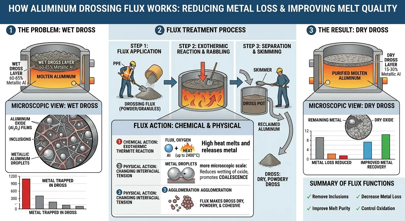
Aluminum melt treatment fluxes are inorganic salt-based or chemical compound formulations applied to molten aluminum at temperatures of 680–780°C to perform three critical metallurgical functions: degassing (removing dissolved hydrogen gas that causes porosity), drossing (separating and removing non-metallic inclusions and oxide films from the melt surface), and furnace wall cleaning (dissolving and removing sintered oxide buildups from furnace linings) — with AdTech’s flux product range covering granular degassing flux, powdered drossing flux, covering flux, and refining flux in formulations based on chloride-fluoride salt systems, achieving hydrogen content reductions of 50–80% and dross metal loss reductions of 40–60% when applied correctly in aluminum foundry and smelting operations.
If your project requires the use of Aluminum Melt Treatment Fluxes, you can contact us for a free quote.
At AdTech, we formulate, manufacture, and supply aluminum melt treatment fluxes to foundries, die casting operations, secondary aluminum smelters, and continuous casting facilities on a global basis. The metallurgical challenges our customers face are consistent across geographies: excessive porosity in castings traced to dissolved hydrogen, unacceptably high dross metal loss consuming valuable aluminum, furnace productivity losses from oxide buildup on walls and hearths, and inconsistent casting mechanical properties linked to inadequate inclusion removal. Flux treatment, when properly specified and applied, addresses all of these challenges simultaneously.

The Metallurgical Case for Aluminum Melt Treatment: Understanding Hydrogen and Inclusion Problems
Molten aluminum presents two fundamental quality challenges that flux treatment addresses directly. Understanding why these problems exist — not just that they exist — is essential for selecting and applying fluxes effectively.
The Hydrogen Solubility Problem
Aluminum has an unusual and problematic relationship with hydrogen. At room temperature, solid aluminum dissolves almost no hydrogen (approximately 0.036 ml H₂ per 100g Al at the melting point solid side). At its melting point liquid state, aluminum dissolves approximately 0.69 ml H₂ per 100g Al — a 20-fold increase in solubility across the solid-liquid transition.
This dramatic solubility change has severe practical consequences during casting. As the liquid aluminum solidifies in the mould, hydrogen solubility drops precipitously. The excess dissolved hydrogen cannot remain in solution and must leave the metal. If it cannot escape through the solidifying metal surface quickly enough (which in most casting situations it cannot, due to rapid solidification), it forms gas bubbles that become trapped porosity in the solidified casting.
The hydrogen enters the aluminum melt from multiple sources: atmospheric moisture (H₂O reacts with molten aluminum: 2Al + 3H₂O → Al₂O₃ + 3H₂), wet or contaminated scrap (organic residues, surface moisture, oil contamination), wet refractory linings and furnace tools, humid combustion gases in gas-fired furnaces, and wet alloy additions.
The quantitative target for most aluminum casting applications is a dissolved hydrogen content below 0.10–0.15 ml H₂ per 100g Al before casting. For critical aerospace or pressure-tight applications, the target may be below 0.08 ml/100g. Untreated secondary aluminum melts commonly contain 0.30–0.60 ml/100g — three to six times the acceptable level.
The Inclusion and Oxide Film Problem
Simultaneously with the hydrogen problem, molten aluminum accumulates non-metallic inclusions that degrade casting quality:
Surface oxide films (Al₂O₃ bifilms): Form instantly when the metal surface contacts air. Turbulence folds these films into the melt body, creating double-layer oxide inclusions (bifilms) with an unbonded internal surface that acts as a pre-existing crack in the solidified casting.
Spinels (MgAl₂O₄): Form in magnesium-bearing alloys (including A356) from the reaction of magnesium with aluminum oxide. Spinel inclusions are harder and more stable than Al₂O₃, making them particularly damaging to machining operations.
Alkali metal compounds: Sodium and calcium from scrap contamination or flux carry-over form aluminum-alkali compounds that reduce surface tension and increase hydrogen absorption, compounding the porosity problem.
Refractory fragments: Physical wear particles from ladle linings, furnace walls, and tools that contaminate the melt stream.
Effective flux treatment addresses both the hydrogen problem (through degassing flux application) and the inclusion problem (through drossing and refining flux application), working synergistically to produce clean, low-hydrogen metal ready for casting or filtration.
Classification of Aluminum Melt Treatment Fluxes: Types, Functions, and Chemistry
Aluminum melt treatment fluxes are not a single product — they are a family of chemically distinct formulations, each designed to perform a specific metallurgical function. Using the wrong flux type for a given function produces poor results and may introduce new problems.
Primary Flux Categories
| Flux Type | Primary Function | Secondary Functions | Physical Form | Typical Application |
|---|---|---|---|---|
| Degassing flux | Hydrogen removal | Some inclusion flotation | Granular or powder | Lance injection into melt body |
| Drossing flux | Dross separation and fluidity | Metal recovery from dross | Powder or granular | Surface application and stirring |
| Covering flux | Melt surface protection | Hydrogen barrier | Granular | Surface blanket layer |
| Refining flux | Inclusion removal and coagulation | Alkali removal | Powder or tablet | Injection or stirring |
| Cleaning flux | Furnace wall cleaning | Hearth cleaning | Granular | Direct application to furnace surfaces |
| Combined (multipurpose) flux | Multiple simultaneous functions | Various | Powder or granular | General melt treatment |
| Salt-free / low-chloride flux | Degassing (environmentally optimized) | Reduced emission | Powder or tablet | Environmentally regulated operations |
Flux Selection Decision Framework
Flux type selection depends on the specific metallurgical objective:
Primary objective: Porosity reduction → Specify degassing flux; apply via lance injection or rotary degassing unit for maximum hydrogen removal efficiency.
Primary objective: Dross metal recovery → Specify drossing flux; apply to dross surface and work into dross body to liquefy metal inclusions.
Primary objective: Inclusion cleanliness → Specify refining flux; combine with ceramic foam filtration downstream for maximum effect.
Primary objective: Furnace productivity → Specify cleaning flux; apply during planned maintenance periods to dissolve oxide buildup.
General production improvement → Specify multipurpose flux combining degassing, drossing, and refining functions; best for operations without dedicated flux injection systems.

Degassing Flux: Specifications, Mechanisms, and Application Methods
How Degassing Flux Works
Degassing flux removes dissolved hydrogen from molten aluminum through a mechanism that differs fundamentally from simple chemical reaction. The flux does not chemically react with dissolved hydrogen — instead, it creates conditions that allow hydrogen to leave the aluminum melt by diffusion.
When degassing flux granules or powder are injected into the melt below the surface (via lance or rotary degassing unit), the flux materials vaporize or react to generate very fine gas bubbles. These bubbles — primarily from the generation of chlorine gas (Cl₂) from chloride salt components reacting with aluminum — rise through the melt. As each rising bubble contacts dissolved hydrogen in the surrounding metal, the hydrogen diffuses from the metal into the bubble interior (driven by the zero partial pressure of hydrogen inside a fresh bubble) and is carried to the surface and removed.
The efficiency of this process depends on:
- Bubble size: Smaller bubbles have higher surface area per unit volume and collect more hydrogen per unit of gas generated.
- Bubble distribution: Uniformly distributed bubbles throughout the melt depth collect hydrogen more efficiently than large bubbles rising in concentrated streams.
- Bubble residence time: Slower-rising bubbles (smaller size) spend more time in contact with the metal, collecting more hydrogen.
- Melt temperature: Higher temperature increases hydrogen diffusion coefficient, improving removal rate.
This is why rotary degassing units (which produce very fine, uniformly distributed bubbles through a spinning rotor) dramatically outperform simple lance injection (which produces larger, less uniformly distributed bubbles). Degassing flux amplifies both methods but works much more effectively in rotary degassing systems.
AdTech Degassing Flux Chemical Specifications
| Parameter | Standard Grade | Premium Grade | Test Method |
|---|---|---|---|
| Primary salt system | KCl + NaCl + Na₃AlF₆ | KCl + NaCl + K₂TiF₆ + Na₃AlF₆ | XRF / wet chemistry |
| Chloride content (total) | 55–70% | 50–65% | Titration |
| Fluoride content | 10–18% | 12–20% | Ion selective electrode |
| Alkali metal content (Na+K) | 30–45% | 28–42% | Flame photometry |
| Moisture content | ≤ 0.3% | ≤ 0.2% | Karl Fischer / LOD |
| Particle size (granular) | 0.5–3.0mm | 0.5–2.5mm | Sieve analysis |
| Melting point range | 650–720°C | 640–710°C | DSC analysis |
| Bulk density | 0.85–1.20 g/cm³ | 0.90–1.25 g/cm³ | Cylinder method |
| pH (10% solution) | 7.5–9.5 | 7.5–9.5 | pH meter |
Degassing Flux Performance Targets
| Performance Parameter | Baseline (No Treatment) | After Degassing Flux (Lance) | After Degassing Flux (Rotary) |
|---|---|---|---|
| Dissolved H₂ (ml/100g Al) | 0.30–0.60 | 0.15–0.25 | 0.08–0.15 |
| Density Index (%) | 8–25% | 3–8% | 1–4% |
| K-mold Bifilm Index | High | Moderate | Low-Moderate |
| Treatment time (per ton) | N/A | 8–15 minutes | 12–20 minutes |
| Flux consumption (kg/ton Al) | N/A | 1.5–3.0 kg | 0.8–2.0 kg |
| Gas consumption (N₂ or Ar, m³/ton) | N/A | 0.5–1.5 | 2.0–5.0 |
Degassing Flux Application Methods
Method 1: Manual lance injection
A steel lance pipe (diameter 25–40mm) attached to a nitrogen or argon gas supply is plunged into the melt. Degassing flux granules or powder are introduced through the lance via a flux injector unit or a simple pressurized hopper. Gas carries the flux into the melt body where it disperses, vaporizes, and generates treatment bubbles.
This method is appropriate for small-to-medium operations (melts below 3–5 tons) and for operations without rotary degassing equipment. It is lower in capital cost but less efficient in hydrogen removal per kg of flux used.
Method 2: Rotary degassing unit with flux injection
A graphite rotor spinning at 200–600 RPM breaks the combined nitrogen/argon carrier gas and entrained flux powder into very fine bubbles (typical diameter 2–8mm versus 15–40mm for lance injection). These fine bubbles distribute uniformly through the melt volume, providing dramatically superior hydrogen removal efficiency.
AdTech manufactures rotary degassing units (graphite rotor and shaft systems) that integrate directly with our flux product line for optimized system performance. We recommend this method for any operation above 2 tons melt capacity where casting quality is critical.
Method 3: Flux tablet/briquette submergence
Pre-formed flux tablets or briquettes are plunged below the melt surface using a steel bell plunger. The tablet dissolves and generates treatment gases. This method is simpler than injection equipment and suitable for smaller operations, though efficiency is lower than rotary degassing.
Method 4: Powder spreading with stirring
For operations with no injection equipment, degassing flux powder can be spread across the melt surface and worked in with a steel ladle or skimmer. This is the least efficient method but provides meaningful improvement over no treatment.
Drossing Flux: Specifications, Mechanisms, and Metal Recovery
The Dross Problem in Aluminum Processing
Dross is the surface layer that forms on molten aluminum through oxidation, nitridation, and entrapment of non-metallic materials. In secondary aluminum operations (recycling foundries and smelters), dross generation can represent 2–8% of the total melt weight — with metallic aluminum often comprising 40–70% of the dross mass. This trapped metal represents direct revenue loss and is the primary target of drossing flux treatment.
The composition of typical aluminum dross:
- Metallic aluminum (trapped): 40–70%.
- Aluminum oxide (Al₂O₃): 15–35%.
- Aluminum nitride (AlN): 5–15%.
- Magnesium oxide (MgO): 1–5% (in Mg-bearing alloys)
- Spinels (MgAl₂O₄): 2–8%.
- Other salts, carbides, other oxides: 2–5%.
How Drossing Flux Works
Drossing flux acts on the dross layer through two primary mechanisms:
Mechanism 1: Reduction of dross melting point and viscosity
The chloride-fluoride salt components of drossing flux dissolve into the oxide matrix of the dross, reducing its melting point and viscosity. This allows the metallic aluminum droplets trapped within the dross structure to coalesce and drain back into the melt, increasing metal recovery.
Mechanism 2: Surface tension modification
Drossing flux reduces the surface tension of the molten aluminum relative to the oxide films, causing oxide films to release their trapped metal content more readily. This is particularly important for the fine, dispersed metal droplets that represent the majority of dross metal content.
The practical result: dross treated with appropriate drossing flux becomes fluffy, dry, and non-sticky (sometimes described as “short” dross), making it easy to skim cleanly from the melt surface while leaving maximum metal behind. Untreated dross remains wet, sticky, and difficult to skim — dragging metal with it and leaving adhesive residue on furnace walls.
AdTech Drossing Flux Specifications
| Parameter | Standard Drossing Flux | Heavy-Duty Drossing Flux | Low-Salt Drossing Flux |
|---|---|---|---|
| Primary composition | KCl-NaCl-Na₃AlF₆ | KCl-NaCl-Na₃AlF₆-KF | Organic salt + fluoride |
| Chloride content | 60–75% | 55–70% | 20–40% |
| Fluoride content | 8–15% | 12–20% | 5–15% |
| Application temperature | 700–760°C | 700–780°C | 680–750°C |
| Particle form | Powder (0.1–0.5mm) | Granular (0.5–2.0mm) | Powder |
| Moisture content | ≤ 0.3% | ≤ 0.25% | ≤ 0.4% |
| Dosing rate | 5–15 kg/ton dross | 8–18 kg/ton dross | 4–12 kg/ton dross |
| Metal recovery improvement | 15–35% vs. no flux | 20–40% vs. no flux | 10–25% vs. no flux |
Dross Metal Recovery Performance Data
| Treatment Method | Dross Metal Content (after skimming) | Metal Recovery vs. Baseline |
|---|---|---|
| No treatment (baseline) | 55–70% metal in dross | Baseline |
| Manual flux + stirring | 35–50% metal in dross | +15–25% metal recovered |
| Mechanical dross press (no flux) | 30–45% metal in dross | +20–30% metal recovered |
| Drossing flux + mechanical press | 15–25% metal in dross | +35–50% metal recovered |
| AdTech heavy-duty drossing flux | 18–28% metal in dross | +30–45% metal recovered |
Dross Application Procedure
The correct drossing flux application sequence maximizes metal recovery:
- Allow dross to accumulate on the melt surface naturally during the melting cycle.
- Reduce agitation and allow the melt to calm for 2–3 minutes before flux application.
- Apply drossing flux powder uniformly across the entire dross surface at the recommended dosing rate.
- Work the flux into the dross using a perforated steel skimmer or mechanical dross stirrer — the flux must contact the interior of the dross mass, not just the surface.
- Allow 3–5 minutes for the flux to act (metal droplets coalesce and drain).
- Skim the treated dross cleanly in one direction, not repeatedly scraping back and forth (which reincorporates metal).
- Check that the melt surface is clean and bright after skimming — residual dark areas indicate incomplete dross removal.
Covering and Protective Flux: Preventing Oxidation During Melting and Holding
The Need for Melt Surface Protection
Between active treatment operations (degassing, drossing), molten aluminum left exposed to the furnace atmosphere continues to oxidize at the surface. This oxidation generates new dross, absorbs atmospheric hydrogen, and degrades the metal quality that flux treatment has achieved.
Covering flux solves this problem by floating as a molten salt layer on the aluminum melt surface, physically separating the metal from the atmosphere. The flux layer must:
- Melt and spread at aluminum holding temperatures (680–750°C).
- Have lower density than aluminum (2.7 g/cm³) to float stably.
- Create a continuous, non-permeable barrier to atmospheric gases.
- Not react chemically with the aluminum or introduce contamination.
- Remain fluid enough to be skimmed off before casting.
AdTech Covering Flux Specifications
| Parameter | Standard Covering Flux | High-Temperature Covering Flux |
|---|---|---|
| Composition | KCl-NaCl base | KCl-NaCl-K₂SO₄ base |
| Chloride content | 65–80% | 60–75% |
| Fluoride content | 3–8% | 5–12% |
| Application temperature | 680–740°C | 700–780°C |
| Melting point of flux | 620–680°C | 640–700°C |
| Flux density | 1.6–1.9 g/cm³ | 1.7–2.0 g/cm³ |
| Layer thickness (effective) | 15–30mm | 20–40mm |
| Application rate | 5–10 kg/m² melt surface | 6–12 kg/m² melt surface |
| H₂ absorption prevention | 60–80% reduction | 70–85% reduction |
| Particle size | 2–8mm granular | 2–8mm granular |
Covering Flux in Long-Duration Holding Operations
For aluminum holding furnaces that maintain metal at temperature for extended periods (between casting cycles, overnight holding, or shift-change holding periods), covering flux provides a quantifiable benefit. Without covering flux, metal in a gas-fired holding furnace at 720°C absorbs approximately 0.03–0.06 ml H₂ per 100g Al per hour of holding. With a properly maintained covering flux layer, this absorption rate drops to 0.005–0.015 ml H₂ per 100g Al per hour — a 4–6× reduction in hydrogen pickup rate during holding.
This means that a 4-hour overnight hold that would raise hydrogen content from 0.10 to 0.30 ml/100g (requiring re-degassing before the next shift’s casting) instead raises it only to 0.12–0.15 ml/100g — often eliminating the need for re-degassing and saving both treatment time and flux consumption.
Furnace Wall Cleaning Flux: Removing Sintered Oxide Buildup
The Furnace Productivity Impact of Oxide Buildup
Over weeks and months of operation, aluminum melting furnaces accumulate sintered oxide buildups (also called skulls or bath crusts) on furnace walls, hearth surfaces, and ramp areas. These buildups:
- Trap metallic aluminum, reducing melt yield.
- Reduce furnace capacity as buildup thickness increases.
- Create local hot spots from their insulating effect, accelerating refractory wear.
- Generate oxide inclusions when pieces break off and enter the melt.
- Increase energy consumption per ton of aluminum melted.
Mechanical removal of these buildups (chipping, grinding) is labor-intensive, risks damaging refractory linings, and cannot access complex furnace geometries. Furnace wall cleaning flux dissolves these buildups chemically during furnace operation.
AdTech Furnace Cleaning Flux Specifications
| Parameter | Standard Cleaning Flux | Heavy-Duty Cleaning Flux |
|---|---|---|
| Primary system | KF-NaF-Na₃AlF₆ | Na₃AlF₆-K₂TiF₆-KCl |
| Fluoride content | 25–40% | 35–50% |
| Application temperature | 720–780°C | 740–800°C |
| Physical form | Granular (1–4mm) | Granular (2–5mm) |
| Application frequency | Monthly or quarterly | Quarterly or semi-annual |
| Application method | Direct on oxide buildup | With raking/stirring |
| Oxide dissolution rate | 2–5 kg oxide/kg flux | 3–7 kg oxide/kg flux |
| Contact time required | 15–45 minutes | 20–60 minutes |
Cleaning Flux Application Protocol
- Allow furnace to reach treatment temperature (720–780°C) with melt present.
- Reduce or stop metal flow into the furnace.
- Apply cleaning flux directly onto the oxide buildup areas.
- Allow flux to react without disturbance for 15–30 minutes.
- Rake softened oxide buildup into the melt body where it dissolves into the flux layer.
- Skim the resulting flux-oxide mixture from the melt surface.
- Resume normal operations after removing cleaning flux residue.
We recommend scheduling cleaning flux treatment during planned maintenance windows rather than during production, since the process temporarily reduces melt quality and generates substantial dross.
Flux Chemistry: Chloride-Fluoride Salt Systems and Their Metallurgical Functions
The Foundation: Why KCl-NaCl-Fluoride Systems Work
The dominant chemistry in commercial aluminum melt treatment fluxes is the potassium chloride-sodium chloride-fluoride system. Understanding why this particular chemistry is chosen explains how to evaluate and compare flux products.
Potassium chloride (KCl) and sodium chloride (NaCl):
The KCl-NaCl binary system forms a eutectic at approximately 51% NaCl / 49% KCl (by weight) with a melting point of 657°C — conveniently below typical aluminum processing temperatures (680–780°C). This eutectic composition produces a low-viscosity molten salt that spreads readily over aluminum melt surfaces and penetrates dross structures effectively.
The alkali chlorides (KCl, NaCl) are the carrier phase for the more reactive fluoride components and provide the low melting point and good fluidity that makes the flux functionally useful.
Fluoride components (Na₃AlF₆, KF, K₂TiF₆, Na₂SiF₆):
Fluoride compounds are the chemically active components that provide the flux’s metallurgical effectiveness. Their functions include:
- Cryolite (Na₃AlF₆): Dissolves aluminum oxide (Al₂O₃) films, enabling oxide inclusions to be incorporated into the flux phase rather than remaining in the metal. Also reduces the melting point of the salt mixture.
- Potassium fluoride (KF): Aggressive oxide dissolver; improves wetting of flux onto metal surfaces; contributes to alkali metal removal from the melt.
- Potassium fluorotitanate (K₂TiF₆): Used in premium degassing flux formulations; releases titanium fluoride complexes that improve the efficiency of hydrogen bubble nucleation on flux particles.
- Sodium hexafluorosilicate (Na₂SiF₆): Less common; used in some cleaning flux formulations for aggressive oxide dissolution.
Salt-Free and Low-Chloride Flux Alternatives
Regulatory pressure in several countries (particularly European Union members with tight chloride emission limits) has driven development of alternative flux chemistries that reduce or eliminate chloride content:
Organic salt systems: Some flux formulations replace chloride salts partially with organic compounds (glycines, oxalates) that provide degassing action through thermal decomposition without generating HCl gas. These are less efficient than chloride-based systems but acceptable in regulatory environments requiring chloride emission reduction.
Nitrogen/argon-only degassing: The most extreme low-emission approach eliminates chemical flux entirely, relying solely on inert gas bubbling through rotary degassing equipment. Efficiency is somewhat lower than combined gas-flux treatment, but regulatory compliance is straightforward.
AdTech low-chloride flux range: We produce a dedicated low-chloride flux series for customers in emission-regulated markets, formulated to reduce HCl gas generation by 60–80% versus standard chloride-based flux while maintaining 80–90% of the metallurgical performance of full-chloride formulations.
Flux Application Methods: Lance Injection, Rotary Degassing, and Manual Application
Comparative Efficiency of Application Methods
The same flux product delivers dramatically different results depending on the application method. This is one of the most important and least-understood aspects of aluminum flux treatment in practice.
| Application Method | H₂ Removal Efficiency | Flux Consumption (kg/ton Al) | Capital Cost | Best For |
|---|---|---|---|---|
| Surface spread + stirring | 20–35% H₂ reduction | 3.0–5.0 | Very Low | Small operations, emergency treatment |
| Flux tablet plunging | 30–50% H₂ reduction | 2.0–4.0 | Low | Small to medium foundries |
| Lance injection (N₂ carrier) | 45–65% H₂ reduction | 1.5–3.0 | Low-Medium | Medium foundries without rotary unit |
| Rotary degassing unit | 60–80% H₂ reduction | 0.8–2.0 | Medium-High | Any operation requiring low porosity |
| Rotary + flux injection combined | 70–90% H₂ reduction | 0.5–1.5 | High | Critical quality applications |
Rotary Degassing Unit Integration with Flux Treatment
AdTech manufactures graphite rotor and shaft degassing systems that integrate with our flux injection product line. The rotary degassing unit approach to flux application offers several advantages over lance injection:
Finer bubble generation: The spinning rotor (200–600 RPM) breaks the combined gas-flux stream into bubbles typically 2–5mm diameter, versus 15–40mm for lance injection. Smaller bubbles have 6–10× more surface area per unit volume, dramatically improving hydrogen collection efficiency per cubic meter of gas used.
Uniform distribution: The rotor’s horizontal pumping action distributes bubbles throughout the melt volume rather than allowing them to rise in concentrated columns from a fixed lance position.
Reduced flux consumption: Because each bubble is smaller and carries hydrogen more efficiently, less total flux is needed per ton of aluminum treated to achieve equivalent hydrogen reduction.
Consistent results: Operator variability has minimal impact on rotary degassing results — the rotor speed, gas flow rate, and treatment time fully determine the metallurgical outcome, unlike lance injection where operator technique significantly affects bubble distribution.
Treatment Protocol for Rotary Degassing with Flux
The following protocol applies to standard aluminum alloy degassing using AdTech degassing flux with a rotary degassing unit:
| Step | Action | Parameter |
|---|---|---|
| 1. Temperature verification | Check melt temperature | Target 710–740°C (720°C optimal) |
| 2. Dross removal | Skim existing dross before degassing | Remove all visible dross |
| 3. Rotor insertion | Lower rotor to 100–150mm above hearth | Avoid contact with hearth |
| 4. Gas purge (no rotation) | Purge gas lines and rotor | 30 seconds at low flow |
| 5. Start rotation | Initiate rotor rotation | Ramp to 300–400 RPM |
| 6. Gas flow | Set carrier gas (N₂ or Ar) | 4–8 L/min per ton Al |
| 7. Flux injection | Start flux feed | 0.8–1.5 kg/ton Al over treatment duration |
| 8. Treatment duration | Maintain full treatment | 12–18 minutes per ton |
| 9. Final purge | Gas without flux (last 2 minutes) | Purge residual flux from rotor |
| 10. Rotor removal | Lift rotor before stopping rotation | Prevent metal splash |
| 11. Post-treatment dross | Remove treatment byproduct dross | Skim clean before casting |
Technical Specifications and Performance Data for AdTech Flux Products
AdTech Complete Flux Product Specifications
| Product | Type | Composition (main) | Form | Dosing Rate | Primary Application |
|---|---|---|---|---|---|
| AdTech DG-1 | Degassing flux | KCl 45%, NaCl 25%, Na₃AlF₆ 20%, K₂TiF₆ 10% | Granular 0.5–2mm | 1.0–2.0 kg/ton | Rotary degassing injection |
| AdTech DG-2 | Degassing flux | KCl 40%, NaCl 30%, Na₃AlF₆ 18%, KF 12% | Powder 0.1–0.5mm | 1.5–3.0 kg/ton | Lance injection |
| AdTech DR-1 | Drossing flux | KCl 55%, NaCl 20%, Na₃AlF₆ 15%, KF 10% | Powder 0.1–0.5mm | 5–15 kg/ton dross | Surface dross treatment |
| AdTech DR-2 | Heavy drossing flux | KCl 50%, NaCl 18%, Na₃AlF₆ 18%, KF 14% | Granular 0.5–2mm | 8–18 kg/ton dross | Secondary smelter dross |
| AdTech CV-1 | Covering flux | KCl 65%, NaCl 25%, Na₃AlF₆ 10% | Granular 2–8mm | 5–10 kg/m² | Holding furnace protection |
| AdTech RF-1 | Refining flux | KCl 40%, NaCl 20%, Na₃AlF₆ 25%, KF 15% | Powder 0.1–0.5mm | 1.5–3.0 kg/ton | Inclusion removal + alkali removal |
| AdTech CL-1 | Cleaning flux | Na₃AlF₆ 40%, KF 30%, KCl 30% | Granular 1–4mm | 10–20 kg/m² oxide | Furnace wall cleaning |
| AdTech LC-1 | Low-chloride flux | Organic salt 50%, fluoride 35%, KCl 15% | Powder 0.1–0.5mm | 1.5–2.5 kg/ton | Emission-regulated operations |
Performance Validation Data
AdTech flux products are tested against the following performance criteria before release to market:
| Test Parameter | Method | Acceptance Criterion |
|---|---|---|
| Moisture content | Karl Fischer titration | ≤ 0.30% |
| Chemical composition (XRF) | XRF analysis | Within ±2% of specification |
| Melting point | DSC / hot plate test | Within 20°C of target |
| Particle size distribution | Sieve analysis | Within specification ±10% |
| Degassing efficiency (aluminum test) | Density Index before/after | ≥ 50% DI reduction (DG grades) |
| Metal recovery (drossing test) | Controlled dross treatment | ≥ 20% metal recovery improvement (DR grades) |
| Hydrogen absorption prevention | Timed exposure test | ≥ 60% H₂ absorption reduction (CV grades) |
| Chloride emission (HCl gas) | Gas measurement during application | Within environmental compliance limits |
Interaction Between Flux Treatment and Ceramic Foam Filtration
Why Flux and Filtration Are Complementary, Not Alternatives
A misconception we encounter regularly is the idea that a foundry must choose between flux treatment and ceramic foam filtration — that installing a filtration system means flux treatment becomes unnecessary. This reflects a misunderstanding of what each process accomplishes.
Flux treatment (degassing and drossing) removes:
- Dissolved hydrogen gas (filtration cannot do this)
- Large oxide films and dross from the melt surface and body (through flotation and coagulation)
- Alkali metals (Na, Ca, K) that increase hydrogen absorption tendency.
- Coarsely distributed inclusions through skimming.
Ceramic foam filtration removes:
- Fine oxide bifilms and inclusion particles that remain after flux treatment.
- Small refractory fragments.
- Fine intermetallic particles.
- The inclusion population that flux treatment leaves behind but that still causes casting defects.
The two technologies address different inclusion size ranges and different metallurgical problems. Flux treatment handles the gross hydrogen and large inclusion problem; filtration handles the fine inclusion population that remains after treatment. Used together, they produce metal quality that neither achieves independently.
The Correct Process Sequence
The correct sequence for aluminum melt treatment before casting:
1. Charge and melt → Load furnace and melt the charge.
2. Alloy and temperature adjustment → Add alloying elements, adjust temperature.
3. Drossing flux treatment → Apply drossing flux, work, and skim dross.
4. Degassing flux treatment → Apply degassing flux via rotary unit or lance; complete hydrogen removal.
5. Post-treatment dross removal → Skim byproduct dross from degassing treatment.
6. Grain refiner addition → Add AlTi5B1 or AlTiB2 grain refiner (5–10 minutes before casting).
7. Transfer to casting station → Minimize turbulence and reoxidation during transfer.
8. Ceramic foam filtration → Filter during mould filling through Al₂O₃ foam filter in the gating system.
9. Casting → Fill mould through filtered metal stream.
This sequence is not arbitrary — placing filtration after flux treatment ensures the filter sees relatively clean metal (flux has removed large inclusions), maximizing filter service life and extending the period before premature blockage occurs.
Safety, Environmental Compliance, and Handling Requirements
Health and Safety Hazards in Flux Handling
Aluminum melt treatment fluxes are industrial chemicals that require appropriate handling controls:
Moisture sensitivity: All chloride-fluoride flux products absorb atmospheric moisture aggressively. Reacting flux with moist atmosphere generates hydrogen chloride (HCl) gas — a severe respiratory irritant. Store flux in sealed containers in dry conditions. Never introduce wet flux into a molten aluminum bath — the violent steam generation can spray molten metal.
HCl gas generation during application: When chloride-containing flux contacts molten aluminum, hydrogen chloride (HCl) and chlorine (Cl₂) gases are generated as byproducts of the degassing reaction. Both gases are respiratory irritants and corrosive. Flux treatment areas must have adequate local exhaust ventilation to maintain HCl concentrations below OSHA PEL of 5 ppm (ceiling limit).
Hydrogen fluoride (HF) generation: Fluoride components can generate HF gas under some conditions, particularly at high temperatures or with wet flux. HF is a severe systemic toxin — OSHA PEL of 3 ppm TWA. Respiratory protection and ventilation are essential.
Molten salt burns: Flux materials melt at 650–720°C and behave as energetic molten liquids during application. Contact with skin causes severe thermal and chemical burns. Full PPE (face shield, heat-resistant gloves, aluminized suit for close work) is required.
Required PPE for Flux Application
| Task | Required PPE |
|---|---|
| Flux bag handling / transfer | Safety glasses, N95 respirator, nitrile gloves |
| Lance injection operation | Face shield, N95–P100 respirator, heat-resistant gloves, flame-resistant clothing |
| Rotary degassing operation | Face shield, P100 respirator, heat-resistant gloves, FR clothing |
| Dross skimming after treatment | Face shield, P100 respirator, heat-resistant gloves, FR clothing |
| Flux storage area inspection | Safety glasses, dust mask |
Environmental Compliance
Chloride emissions: HCl gas from flux treatment is regulated under Clean Air Act (USA), EU Industrial Emissions Directive, and equivalent national regulations. Permissible emission levels vary by jurisdiction and facility size. Foundries with enclosed degassing stations typically use wet scrubbers or dry sodium bicarbonate scrubbing systems to capture HCl before atmospheric discharge.
Fluoride emissions: HF and particulate fluoride from flux treatment are regulated similarly to chloride emissions. Foundries in regulated jurisdictions should conduct emissions testing after any significant change in flux consumption rate or flux chemistry.
Spent flux / salt slag disposal: The salt slag produced after flux treatment (a mixture of salt flux, aluminum oxide, and entrapped metal) must be disposed of according to applicable hazardous waste regulations. In many jurisdictions, aluminum salt slag is classified as hazardous waste (due to water-reactive aluminum nitride content that generates ammonia and potentially flammable gas on contact with water). AdTech provides waste stream characterization data for our flux products to support customer environmental compliance.
REACH / SDS compliance: All AdTech flux products are registered under applicable chemical control regulations and supplied with current Safety Data Sheets in required languages.
Selecting the Right Flux for Your Aluminum Alloy and Process
Alloy-Specific Flux Selection Considerations
Different aluminum alloy families present different flux treatment challenges:
| Alloy Family | Main Challenge | Recommended Flux Type | Special Consideration |
|---|---|---|---|
| Al-Si (A356, A380, ADC12) | Hydrogen porosity; oxide bifilms | DG-1 or DG-2 degassing + DR-1 drossing | Standard treatment; most common |
| Al-Si-Mg (A357) | Mg oxidation; MgAl₂O₄ spinel | DG-1 + RF-1 refining | Mg-bearing alloys generate more dross |
| Al-Cu (2xx.x) | High H₂ absorption at high temp | DG-1 rotary + CV-1 covering | Higher treatment temperature required |
| Al-Mg (5xx.x) | Aggressive surface oxidation | DR-2 heavy drossing + CV-1 | Mg content dramatically increases dross rate |
| Al-Zn-Mg (7xx.x) | Complex oxide; Zn volatility | DG-2 + RF-1 | Zinc fume management required |
| Secondary / recycled alloys | Very high inclusion load | DR-2 + DG-1 + RF-1 combined | More aggressive treatment needed |
| High-purity Al (1xxx) | Hydrogen absorption; minimal other issues | DG-1 (low dose) | Very clean; minimal drossing flux needed |
Process-Specific Flux Dosing Guide
| Process Type | Furnace Size | Recommended Flux Products | Total Flux Dose (kg/ton Al) |
|---|---|---|---|
| Gravity die casting (small) | 0.5–2 tons | DG-2 lance + DR-1 | 2.5–4.5 kg/ton |
| Gravity die casting (medium) | 2–10 tons | DG-1 rotary + DR-1 | 2.0–3.5 kg/ton |
| High pressure die casting | 5–30 tons | DG-1 rotary + DR-2 | 1.5–3.0 kg/ton |
| Low pressure casting | 2–15 tons | DG-1 rotary + CV-1 + DR-1 | 2.5–4.0 kg/ton |
| Investment casting | 0.1–2 tons | DG-2 + RF-1 tablet | 3.0–5.0 kg/ton |
| Secondary smelting | 20–100 tons | DG-1 + DR-2 heavy + CL-1 periodic | 3.0–6.0 kg/ton |
| Continuous casting | 50–200 tons | DG-1 inline + CV-1 + CFL (periodic) | 1.0–2.5 kg/ton |
Frequently Asked Questions (FAQs)
Q1: What is the difference between degassing flux and drossing flux for aluminum, and do I need both?
Degassing flux and drossing flux perform fundamentally different functions. Degassing flux removes dissolved hydrogen gas from the melt body by generating fine bubbles that carry hydrogen to the surface — this reduces casting porosity. Drossing flux acts on the dross layer at the melt surface, reducing its viscosity so that trapped metallic aluminum droplets coalesce and drain back into the melt, improving metal recovery and producing dry, easily-skimmed dross. Most production aluminum foundries benefit from both: degassing flux addresses the internal porosity problem, while drossing flux reduces metal loss and surface inclusion generation. Some multipurpose flux formulations provide both functions simultaneously, though at slightly lower efficiency than dedicated single-purpose products.
Q2: How much hydrogen can degassing flux realistically remove from molten aluminum?
The achievable hydrogen reduction depends critically on the application method. Using degassing flux with a rotary degassing unit at the correct dosing rate (0.8–2.0 kg/ton) and treatment time (12–20 minutes per ton), dissolved hydrogen content in secondary aluminum melts can be reduced from 0.30–0.60 ml H₂ per 100g Al down to 0.08–0.15 ml/100g — a 50–75% reduction. Lance injection without a rotary unit achieves a more modest 40–60% reduction. Simple surface application achieves only 20–35% reduction. The rotary degassing unit combined with flux injection is the most effective approach for castings requiring low porosity, particularly automotive safety components and pressure-tight castings.
Q3: Why does my degassing flux generate so much smoke and fumes during application?
Smoke and fume generation during flux application is normal and expected — it is a byproduct of the flux chemistry performing its function. The visible fumes are primarily hydrogen chloride (HCl) gas and fine salt particles generated when chloride salts react with moisture and aluminum oxide in the melt. Excessive smoke beyond the normal treatment amount may indicate: wet or moisture-contaminated flux (check storage conditions and container integrity), flux application rate too high for the available ventilation (reduce dosing rate or improve ventilation), or abnormally high moisture content in the melt or furnace atmosphere. Always ensure local exhaust ventilation is operating before starting flux treatment, and wear appropriate respiratory protection regardless of visible smoke level, since HCl is odorless at sub-irritating concentrations.
Q4: Can I use the same flux for both aluminum alloys with different magnesium content?
The base flux chemistry (KCl-NaCl-fluoride system) is compatible with all aluminum alloys, but magnesium-bearing alloys (A356, A357, Mg > 0.2%) require modified treatment approaches. Magnesium oxidizes more aggressively than aluminum, generating significantly more dross per ton of metal. For high-Mg alloys: increase drossing flux dosing rate by 25–40%, use a heavy-duty drossing flux (AdTech DR-2) rather than standard drossing flux, and increase covering flux application rate to protect the Mg-containing melt surface between treatment cycles. Magnesium also slightly reduces the efficiency of degassing flux by reacting preferentially with some fluoride components — this effect is minor at Mg < 0.5% but meaningful at higher Mg levels.
Q5: What is Density Index and how does it measure flux treatment effectiveness?
The Density Index (DI) test is the most widely used field measurement of dissolved hydrogen content in molten aluminum. Two small metal samples are solidified simultaneously — one at atmospheric pressure, one under vacuum (typically 80–100 mbar). Both samples are weighed. The Density Index is calculated as: DI (%) = (atmospheric density — vacuum density) / atmospheric density × 100. A DI of 0% indicates no porosity difference between samples (essentially hydrogen-free metal). A DI above 5% indicates significant dissolved hydrogen. Most automotive casting specifications require DI below 2–4%. Aerospace applications typically require DI below 1–2%. Take DI measurements before and after flux treatment to directly quantify the treatment effect: a well-executed rotary degassing treatment with AdTech degassing flux should reduce DI from 8–20% (untreated secondary aluminum) to 1–4%.
Q6: How long after degassing treatment does molten aluminum remain clean before hydrogen pick-up becomes a problem again?
Degassed aluminum reabsorbs hydrogen from the furnace atmosphere at a rate that depends primarily on furnace atmosphere moisture content and melt surface condition. In a gas-fired furnace with exposed melt surface, hydrogen reabsorption raises the dissolved content by approximately 0.03–0.08 ml H₂ per 100g Al per hour. In an induction furnace with lower moisture exposure, reabsorption is slower (0.01–0.04 ml/100g per hour). With covering flux maintaining a salt layer over the melt surface, reabsorption slows to approximately 0.005–0.020 ml/100g per hour. Practical implication: for standard castings, degassed metal should be cast within 30–60 minutes of treatment. For critical applications (aerospace, pressure-tight parts), cast within 20–30 minutes. If holding time exceeds these limits, re-treat with a reduced-dose degassing flux before casting.
Q7: What is the correct temperature for aluminum flux treatment, and does temperature significantly affect performance?
The optimal temperature window for most aluminum melt flux treatment is 710–740°C, with 720°C being ideal for standard alloys. This temperature window balances: metal fluidity (higher temperature improves flux distribution and bubble release), flux activity (most flux systems have optimal reaction kinetics at 700–740°C), and hydrogen diffusion rate (higher temperature increases hydrogen diffusion coefficient, improving removal rate). Treatment below 680°C reduces flux effectiveness because the flux melting point approaches the metal temperature, reducing flux fluidity and penetration. Treatment above 780°C accelerates melt oxidation and increases hydrogen absorption rate from furnace gases. For Al-Cu alloys that process at higher temperatures, consult AdTech’s technical team for flux selection optimized for the 740–780°C range.
Q8: How should I store aluminum melt treatment flux to maintain its effectiveness?
Correct storage is critical for chloride-fluoride flux performance. All AdTech flux products must be stored: in sealed, moisture-proof containers (original sealed bags or drums); in dry conditions with relative humidity below 60%; at ambient temperature (5–35°C), protected from direct sunlight and heat sources; away from water, acids, and incompatible chemicals. Flux exposed to atmospheric moisture absorbs water, which causes clumping, reduces flowability (affecting injection performance), and increases HCl generation during application. Check all containers for seal integrity before use. Do not use flux from damaged or previously opened containers without drying in a controlled oven (120°C for 4–8 hours) if moisture exposure is suspected. Shelf life for properly stored AdTech flux products is 24 months from manufacture date.
Q9: Can flux treatment alone eliminate porosity in aluminum castings, or is filtration also needed?
Flux treatment and ceramic foam filtration address different aspects of aluminum casting quality, and neither alone achieves optimal results. Degassing flux removes dissolved hydrogen — the primary cause of shrinkage microporosity and gas porosity in aluminum castings. However, flux treatment leaves behind a residual population of fine oxide bifilms and inclusion particles that are too small to be captured by skimming or flotation. These fine inclusions — typically smaller than 0.5mm — are responsible for bifilm-related porosity (where the unbonded bifilm interface acts as a void in the solidified metal), mechanical property scatter, and machined surface defects. Ceramic foam filtration (30–40 PPI Al₂O₃ filter in the gating system) captures these residual fine inclusions that flux treatment misses. The combination of proper flux treatment followed by ceramic foam filtration consistently achieves lower porosity and better mechanical property consistency than either process alone.
Q10: What is the recommended flux treatment procedure for a secondary aluminum die casting operation producing A380 alloy?
For secondary aluminum A380 die casting, the recommended treatment sequence using AdTech products is: (1) At the end of the melt cycle, when metal reaches 720–730°C, remove large floating dross by skimming; (2) Apply AdTech DR-1 drossing flux at 5–10 kg per ton of accumulated dross, work into the dross surface with a perforated skimmer, allow 3–5 minutes contact time, then skim treated dross cleanly; (3) Introduce the rotary degassing unit (or lance if rotary unit unavailable) and apply AdTech DG-1 degassing flux at 1.0–1.5 kg/ton aluminum in the furnace, using nitrogen carrier gas at 5–7 L/min per ton, treatment duration 12–15 minutes; (4) After degassing, apply AdTech CV-1 covering flux at 5 kg/m² melt surface to protect the treated metal until casting; (5) Before tapping, remove covering flux residue and check DI (target below 3% for standard die casting); (6) Filter the metal stream through AdTech Al₂O₃ 20–25 PPI ceramic foam filter during shot into the die casting machine shot sleeve.
Summary: Building an Effective Aluminum Melt Treatment Program
The quality of aluminum castings is determined substantially by the quality of the metal treatment process before the metal enters the mould. No amount of tooling optimization, mould design refinement, or process parameter adjustment compensates for metal that enters the gating system carrying excessive dissolved hydrogen and high inclusion loads.
AdTech’s aluminum melt treatment flux product range — covering degassing, drossing, covering, refining, and furnace cleaning applications — provides the complete toolbox for systematic metal quality improvement. The key principles that govern effective flux treatment programs:
Match flux type to function. Degassing flux removes hydrogen; drossing flux improves metal recovery; covering flux prevents reoxidation; refining flux captures fine inclusions. Using the wrong flux type for a given objective delivers poor results regardless of dosing rate.
Application method determines performance ceiling. Rotary degassing with flux injection consistently outperforms lance injection, which outperforms surface application. Invest in application equipment appropriate to your production scale and quality requirements.
Sequence matters. Dross removal before degassing, degassing before casting, filtration during mould filling — the sequence is not arbitrary and each step builds on the previous.
Combine flux treatment with ceramic foam filtration. Flux treatment removes what filtration cannot (dissolved hydrogen), and filtration removes what flux treatment cannot (fine bifilm inclusions). They are complementary technologies, and the best casting quality comes from using both systematically.
Document and measure. Density Index measurement before and after treatment, dross metal content measurement, and casting rejection rate tracking are the metrics that validate flux program effectiveness and identify improvement opportunities.
This article is prepared by AdTech’s technical editorial team with contributions from aluminum metallurgy specialists and foundry process engineers. Product specifications, performance data, and application guidelines reflect AdTech’s current formulations and field experience as of 2025–2026. Contact AdTech’s technical team for application-specific flux selection, dosing optimization, and current pricing.
