ADtech flow control bars and flow tubes (stopper rods) provide precise metering and shutoff of molten aluminum in low-pressure and gravity-fed casting lines, protecting downstream degassing and filtration equipment, enabling stable pour profiles for high-precision castings, and delivering long service life when made from high-silicon, non-wetting refractory materials and installed with correct preheat and sealing practice.
Product overview and intended applications
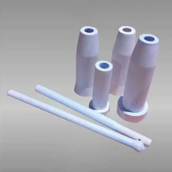
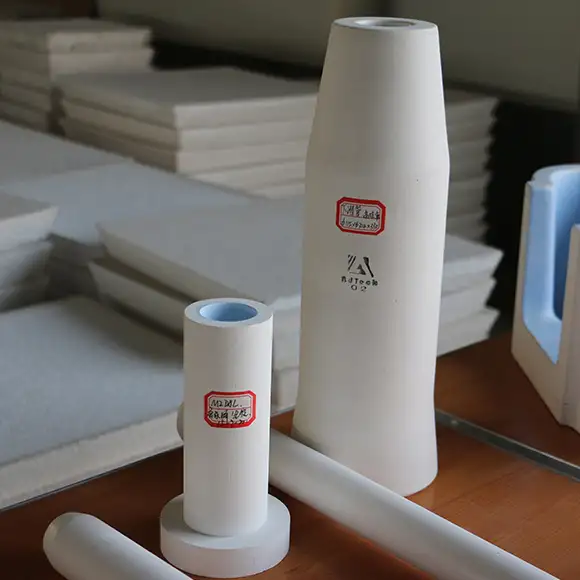
Flow control bars and flow tubes are compact refractory components used to regulate molten metal flow through launders, spouts, and nozzles. They are essential in low-pressure casting, ingot casting and lines that require repeatable filling rates or emergency shutoff. ADtech components are manufactured from high-silicon/alumina refractory mixes that resist corrosion, minimize metal wetting and withstand repeated thermal cycling. They are used together with tube holders, stopper assemblies and optionally with actuator systems for manual or automated control.
How they work and practical mechanics
-
Flow tube (stopper): a cylindrical refractory tube inserted into the launder or nozzle; metal flows through the hollow center or through calibrated openings. Lifting or lowering the tube changes the effective opening area and thus the flow.
-
Flow control bar: a slotted or shaped refractory bar positioned across a spout or slot to form a metering gap. Adjusting bar position or inserting different profile bars changes discharge area and the pour rate.
-
Cooperative use: in many lines a flow tube is used together with a flow control bar or tube holder so operators can fine-tune flow and perform rapid shutoff. Designs can be purely manual or integrated with electric/hydraulic actuators for automated systems.
Key ADtech features and advantages
-
High-silicon/alumina refractory body provides corrosion resistance, low metal adhesion and long life in aluminum melts.
-
Low porosity, high strength firing reduces erosion and allows repeated re-use with minimal deformation.
-
Compatibility with BN coatings to further reduce wetting and ease cleaning.
-
Multiple length and diameter options to fit ladles, launders and pressure-chamber spouts.
-
Interchangeable tube holders and seals for quick replacement and minimal downtime.
-
Optional actuator-ready design for integration into automated flow control systems or level-sensing loops.
Typical materials, coatings and manufacturing notes
-
Baseline chemistry: alumina-rich, SiO2 based cast or sintered bodies with controlled porosity for strength and erosion resistance.
-
Coatings: boron nitride or proprietary anti-wetting layers are often applied to the external surfaces to reduce metal sticking and to simplify skimming and cleaning.
-
Manufacturing: precision firing and dimensional control are critical because sealing faces and tube tolerances determine bypass risk and lifespan.
Common sizes, configurations and selection guide
Table 1: Typical part-family specifications
| Component | Typical sizes | Notes |
|---|---|---|
| Flow tube (stopper) | Ø25 mm – Ø150 mm; lengths 100 mm – 650 mm | Hollow or solid core; custom lengths for nozzle depth. |
| Flow control bar | Width 50 mm – 1200 mm; thickness 10 mm – 50 mm | Slotted or shaped profiles to tune gap and flow. |
| Tube holder / seat | Custom to tube OD | Includes gasket or refractory seat to prevent metal bypass |
| Actuator interface | Flange or clamp-ready | For manual lever, electric lift or hydraulic rod systems. |
Selection depends on pour mass, required pour height, nozzle geometry and automation level. Start with the largest nominal opening that still gives acceptable head loss so the component does not become a choke point.
Installation, preheat and commissioning checklist
-
Verify dimensional fit: confirm tube OD and holder seat tolerances to prevent bypass.
-
Preheat components: heat flow tubes, bars and holders gradually to near-melt temperature to remove moisture and avoid thermal shock. Typical preheat is done in ovens or with induction blankets.
-
Seal and clamp: ensure refractory seats and high-temperature gaskets compress evenly to stop metal bypass around the tube/bar.
-
Functional test: perform cold-run checks for actuator travel, then staged hot trials with sampling to verify flow curves at incremental openings. Record pour rate vs opening for each alloy and pour height.
Flow tuning: practical examples and lookup table
Table 2: Example flow tuning lookup
| Pour height (mm) | Tube lift (mm) | Approx. flow behaviour | Recommended use |
|---|---|---|---|
| 50 – 100 | 0 – 5 | Trickle, good for thin-wall pours | Small precision parts |
| 100 – 200 | 6 – 15 | Controlled laminar fill | Die feeding and steady gating |
| 200+ | 16+ | Fast fill, higher velocity | Large ingots, bulk pour (watch erosion) |
Always validate on-site. Pour curves depend on nozzle geometry, melt viscosity and temperature.
Sealing, bypass prevention and leakage control
A key failure mode is metal bypass between tube and seat. Mitigation measures:
-
Use precision ground seats and matching tube ODs.
-
Install compressible high-temperature gaskets or refractory rope seals where appropriate.
-
Periodically inspect seat surfaces for scoring and replace worn seats rather than over-tightening clamps.
-
Consider coated or lapped mating surfaces to improve sealing and ease maintenance.
Maintenance, wear patterns and service life
-
Typical wear points: tube tip facing the jet, seat face, inner bore for hollow tubes.
-
Indicators to replace: increase in bypass leakage, visible erosion or cracking, change in recorded pour curves for the same opening.
-
Planned spares: keep at least one spare tube per critical nozzle and sets of gaskets/seals for rapid swap.
-
Lifecycle extension: BN coating re-application and light machining of seats can extend usable life between full replacements.
Safety and environmental considerations
-
Preheat to avoid steam or explosive spalling from moisture in refractory parts.
-
When actuators are used, fit mechanical stops and torque limits to prevent catastrophic overtravel into molten metal.
-
Use local fume extraction if fluxing or skimming occurs near the control point.
-
Control inert gas lines and monitor oxygen if argon or nitrogen atmospheres are used near control assemblies.
Troubleshooting quick reference
Table 3: Problems, causes and corrective actions
| Symptom | Likely cause | Immediate corrective action |
|---|---|---|
| Sudden leak / bypass | Seat damage or gasket failure | Stop pour, clamp off or replace gasket, inspect seat |
| Slow response / sticking tube | BN coating degraded or metal adhesion | Withdraw tube, clean and recoat, inspect actuator |
| Rapid erosion at tube tip | High local velocity or abrasive inclusions | Slow pour, install flow spreader, inspect upstream skimming |
| Cracked tube | Thermal shock or mechanical impact | Replace tube, review preheat and handling |
| Inconsistent pourcurve | Wear or deformation of tube | Re-measure pour curves, install new tube if out of spec |
Record incidents to track wear rates versus throughput for better spare planning.
Integration with automation and process control
Flow tubes and bars can be fitted with position feedback transducers and integrated into PLC recipes so pour profiles are repeatable across shifts. Closed-loop control can use level probes, load cells or pour-rate sensors to automatically modulate tube lift for steady fill rates. Patented control-pin and actuator systems exist for precise electro-mechanical control.
Economic case, ROI and productivity gains
Value drivers:
-
Reduced casting defects from unstable pouring.
-
Lower filter erosion and longer filter life due to gentler flow.
-
Faster shutoff reduces metal loss and emergency scrap.
-
Reduced manual intervention when automated.
Table 4: Illustrative ROI snapshot
| Metric | Example |
|---|---|
| Annual throughput | 2,000 tonnes |
| Reduction in pour-related scrap | 0.5% absolute |
| Metal saved annually | 10 tonnes |
| Metal value (example) | $1,800 / tonne |
| Annual metal value saved | $18,000 |
| Typical payback | Often within 6–18 months depending on automation level and scrap costs |
Calculate site-specific ROI with measured scrap and labor costs for accuracy.