
Injektor fluks rotari yang dioperasikan dengan benar dapat menurunkan kadar hidrogen terlarut dalam aluminium cair dari tingkat khas tungku sebesar 0,3–0,6 ml/100 g menjadi 0,10–0,15 ml/100 g dalam waktu 10–15 menit setelah proses perlakuan, sekaligus menghilangkan 60–85% inklusi non-logam bila dipadukan dengan komposisi fluks yang tepat. Itulah kesimpulan praktis yang kami peroleh dari pengoperasian dan pemecahan masalah peralatan ini di puluhan fasilitas pengecoran aluminium, dan itulah sebabnya degassing rotari telah secara luas menggantikan metode lama berbasis lance dan tablet di setiap operasi yang serius dalam menjaga kualitas pengecoran.
Jika proyek Anda memerlukan penggunaan Sistem Injektor Fluks Rotari, Anda dapat hubungi kami untuk mendapatkan penawaran gratis.
Apa Itu Injektor Fluks Rotari dan Sebenarnya Bagaimana Cara Kerjanya?
Injektor fluks rotari, yang kadang-kadang disebut sebagai degasser rotari atau sistem impeler rotari, terdiri dari poros berputar dengan kepala rotor yang dirancang khusus dan terendam dalam aluminium cair. Gas inert, biasanya nitrogen atau argon, mengalir ke bawah melalui poros berlubang dan keluar melalui lubang-lubang pada rotor. Gerakan berputar rotor memecah gas yang keluar menjadi gelembung-gelembung yang sangat halus, sehingga secara drastis meningkatkan luas permukaan yang tersedia untuk penyerapan hidrogen dibandingkan dengan hanya mengalirkan gas melalui lancing yang tidak bergerak.
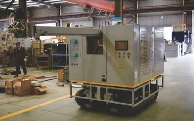
Kami telah mengamati mekanisme ini dalam kondisi terkendali menggunakan perangkat pengamatan transparan selama pengujian pengembangan, dan perbedaan ukuran gelembung antara dispersi rotari dan injeksi lance statis sangat mencolok. Lance menghasilkan gelembung yang seringkali berdiameter beberapa milimeter, naik dengan cepat melalui lelehan dengan waktu kontak yang terbatas. Rotor yang dirancang dengan baik menghasilkan gelembung yang seringkali berukuran kurang dari satu milimeter, tersebar di seluruh zona perlakuan dengan waktu tinggal yang jauh lebih lama sebelum mencapai permukaan.
Perbedaan fisik ini secara langsung memengaruhi efisiensi proses. Hidrogen terlarut dalam aluminium cair berdifusi menuju gelembung-gelembung dengan tekanan parsial rendah dan terbawa bersama gelembung-gelembung tersebut saat naik. Gelembung-gelembung yang lebih kecil dengan luas permukaan total yang lebih besar dan waktu kontak yang lebih lama secara sederhana menarik lebih banyak hidrogen per satuan gas yang dikonsumsi, yang merupakan alasan utama mengapa sistem rotari lebih unggul daripada degassing dengan lance baik dalam hal kecepatan maupun efisiensi gas.
Komponen Utama yang Harus Dipahami oleh Pembeli
Sistem ini tidak hanya terdiri dari rotor dan poros, tetapi juga mencakup unit pasokan gas dan pengatur aliran, motor serta mekanisme penggerak yang mengendalikan kecepatan rotor, struktur penyangga yang memungkinkan penempatan vertikal ke dalam dan keluar dari cairan logam, serta seringkali dilengkapi dengan mekanisme injeksi fluks yang menyalurkan fluks berbentuk bubuk atau butiran bersamaan dengan aliran gas inert.
| Komponen | Fungsi | Bahan Umum |
|---|---|---|
| Kepala rotor | Mengubah gas menjadi gelembung-gelembung halus melalui putaran | Grafit, grafit berlapis keramik |
| Poros | Mengalirkan gas dari sumber ke rotor, mentransmisikan putaran | Grafit, grafit kemurnian tinggi dengan lapisan pelindung |
| Motor penggerak | Mengatur kecepatan putaran | Motor listrik dengan penggerak frekuensi variabel |
| Pengatur aliran gas | Mengatur laju aliran dan tekanan gas inert | Baja tahan karat, pengukur aliran presisi |
| Mekanisme penyangga dan pengangkat | Menempatkan rakitan rotor ke dalam cairan, memungkinkan pengeluaran rakitan tersebut untuk keperluan pemeliharaan | Rangka baja, lift hidrolik atau bertenaga motor |
| Sistem pengumpanan fluks (opsional) | Menggunakan senyawa fluks padat selama proses pengolahan | Pengumpan sekrup atau injeksi pneumatik |
Mengapa Aluminium Perlu Melalui Proses Penghilangan Gas Sebelum Dituang?
Siapa pun yang pernah membelah hasil pengecoran dan menemukan porositas yang tersebar pasti memahami konsekuensi praktisnya, namun prinsip kimia yang mendasarinya menjelaskan mengapa masalah ini pada dasarnya tidak dapat dihindari tanpa adanya intervensi aktif.
Aluminium cair dengan mudah menyerap hidrogen dari kelembapan di atmosfer tungku, dari senyawa terhidrasi pada permukaan skrap, serta dari produk sampingan pembakaran pada tungku berbahan bakar gas. Kelarutan hidrogen dalam aluminium menurun tajam saat logam tersebut mendingin dan mengeras; nilainya sekitar dua puluh kali lebih rendah pada aluminium padat dibandingkan pada keadaan cair pada suhu leleh. Perbedaan kelarutan ini berarti hidrogen terlarut yang semula sangat stabil dalam cairan lelehan tidak memiliki tempat lain untuk pergi selama proses pengerasan kecuali membentuk gelembung gas yang terperangkap di dalam struktur coran.
Gelembung-gelembung yang terperangkap ini muncul sebagai porositas, mulai dari lubang-lubang mikroskopis yang tak terlihat tanpa pembesaran hingga rongga-rongga yang terlihat yang dapat mengganggu integritas struktural dan kualitas permukaan hasil pemesinan. Untuk coran yang harus kedap tekanan seperti rumah transmisi kendaraan bermotor atau komponen hidraulik, porositas sekecil apa pun dapat menyebabkan kegagalan fungsional saat uji tekanan, sehingga proses penghilangan gas bukan sekadar preferensi kualitas, melainkan persyaratan produksi yang mutlak.
Kami telah menganalisis data penolakan dari beberapa fasilitas pelanggan sebelum dan sesudah menerapkan protokol degassing rotari yang tepat, dan pola yang muncul selalu konsisten: tingkat limbah yang terkait dengan porositas biasanya turun dari 8–15% menjadi 2–4% begitu parameter pengolahan disesuaikan dengan tepat untuk paduan logam dan geometri coran yang bersangkutan.
| Kadar Hidrogen (ml/100 g) | Tingkat Risiko Porositas | Kesesuaian untuk Aplikasi Umum |
|---|---|---|
| Di atas 0,30 | Berisiko tinggi | Tidak cocok untuk coran yang harus kedap tekanan atau coran kritis |
| 0.20-0.30 | Risiko sedang | Coran untuk keperluan umum, aplikasi yang tidak kritis |
| 0.15-0.20 | Risiko rendah hingga sedang | Coran struktural standar |
| 0.10-0.15 | Risiko rendah | Casting kedap tekanan, komponen dirgantara |
| Di bawah 0,10 | Risiko sangat rendah | Komponen kedirgantaraan dengan tingkat integritas tinggi, komponen keselamatan kritis |
Bagaimana Perbandingan Metode Injeksi Rotari dengan Metode Degassing Lance dan Metode Lainnya?
Pembeli yang sedang mencari informasi mengenai peralatan ini hampir selalu meminta kami untuk menjelaskan alasan di balik selisih harga yang lebih tinggi dibandingkan alternatif yang lebih sederhana, dan itu adalah pertanyaan yang wajar mengingat harga sistem degassing tipe lance hanya sepersekian dari harga unit rotari.
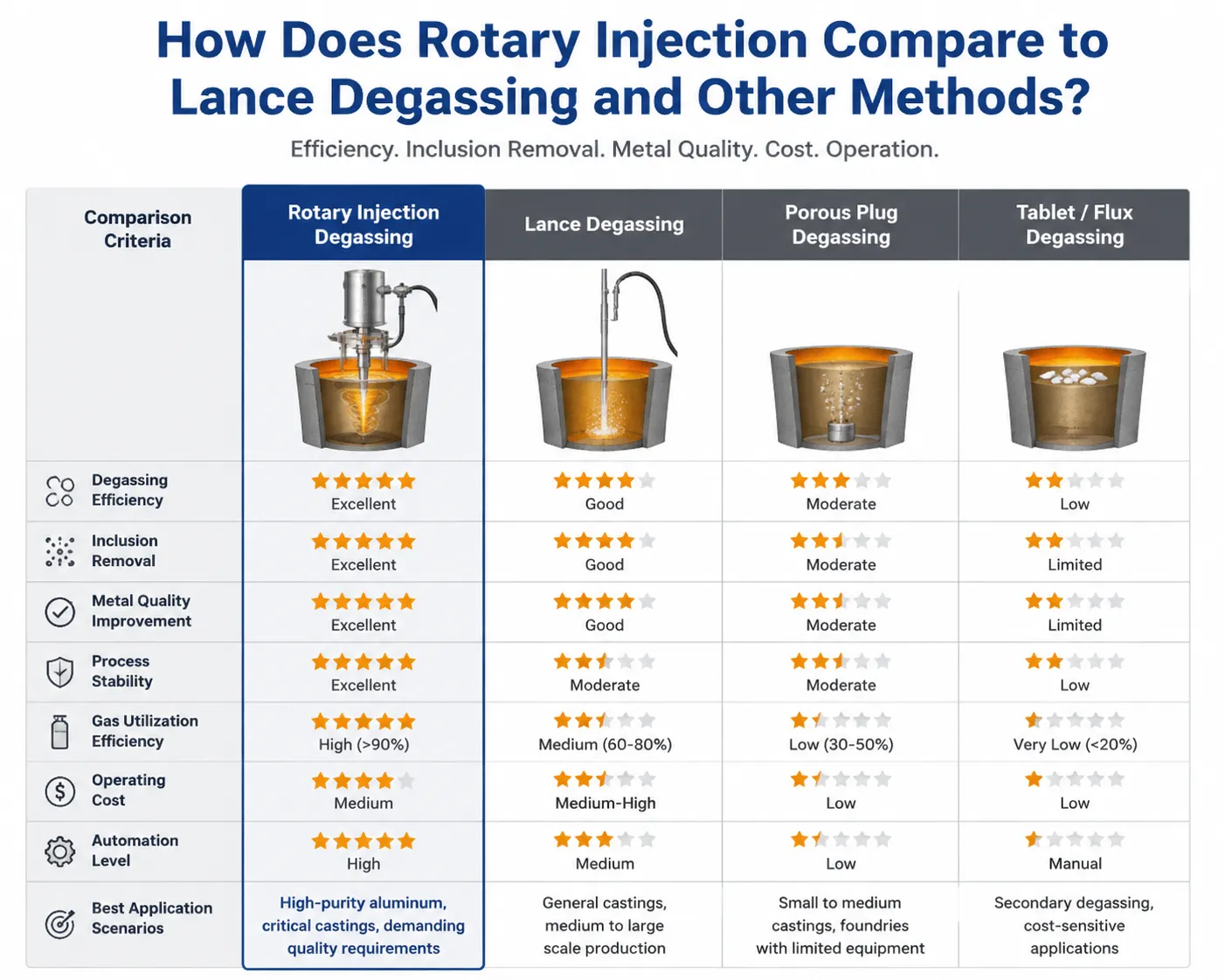
Proses degassing Lance mendorong gas inert melalui pipa yang terendam atau sumbat berpori tanpa dispersi mekanis, sepenuhnya mengandalkan naiknya gelembung secara alami untuk proses penghilangan hidrogen yang terjadi. Metode ini murah, sederhana secara mekanis, dan menghasilkan hasil yang secara terukur lebih buruk karena gelembung yang lebih besar dan waktu kontak dengan logam cair yang lebih singkat secara signifikan mengurangi efisiensi penghilangan hidrogen.
Proses penghilangan gas pada tablet, yang menggunakan senyawa padat yang melepaskan gas saat terurai dalam fase cair, menawarkan kemudahan tanpa perlu investasi peralatan; namun, metode ini memiliki kelemahan berupa waktu pelepasan gas yang tidak konsisten dan hasil keseluruhan yang umumnya lebih buruk dibandingkan dengan metode injeksi rotari terkendali.
Penghilangan gas dengan vakum, yang lebih umum digunakan dalam pengolahan baja dan paduan khusus, menghilangkan gas terlarut dengan cara menurunkan tekanan atmosfer di atas cairan logam, bukan dengan mengalirkan gas melalui cairan tersebut. Metode ini cukup efektif, namun membutuhkan peralatan yang jauh lebih mahal serta waktu pengolahan yang lebih lama, sehingga tidak praktis untuk sebagian besar operasi pengecoran aluminium yang menjalankan jadwal produksi bervolume tinggi.
| Metode Penghilangan Gas | Efisiensi Penghilangan Hidrogen | Waktu Perawatan | Biaya Peralatan | Konsumsi Bahan Bakar |
|---|---|---|---|---|
| Lance/sumbat berpori | Rendah hingga sedang | 20–30 menit | Rendah | Hasil per satuan yang tinggi |
| Penghilangan gas pada tablet | Rendah, tidak konsisten | 15–25 menit | Sangat rendah | N/A (senyawa padat) |
| Injeksi fluks rotari | Tinggi | 8–15 menit | Sedang hingga tinggi | Penggunaan yang wajar dan efisien |
| Degassing vakum | Sangat tinggi | 20–40 menit | Sangat tinggi | Sistem yang sederhana, namun kompleks |
Perbandingan lapangan yang kami lakukan sendiri, yang dilaksanakan di lokasi pelanggan yang bersedia menguji kedua metode tersebut pada batch terpisah dari lelehan yang sama, secara konsisten menunjukkan bahwa sistem rotari mampu mencapai tingkat hidrogen target dalam waktu pengolahan sekitar setengah dari waktu yang dibutuhkan metode lance, sambil menggunakan volume gas total yang setara atau lebih sedikit berkat efisiensi transfer yang meningkat secara drastis.
Seberapa Tinggi Efisiensi Penghilangan Hidrogen yang Sebenarnya Dapat Diharapkan oleh Pembeli?
Lembar spesifikasi pabrikan terkadang menyajikan angka kinerja ideal yang tidak mencerminkan kondisi yang sebenarnya terjadi di lantai pabrik pengecoran, di mana kualitas sisa bahan dan kondisi tungku bervariasi. Kami lebih memilih untuk membagikan rentang nilai yang didasarkan pada kinerja lapangan yang terdokumentasi, daripada skenario terbaik di laboratorium.
Tingkat hidrogen akhir yang dapat dicapai bergantung pada konsentrasi hidrogen awal, waktu perlakuan, kecepatan rotor, laju aliran gas, serta konsistensi suhu lelehan selama proses perlakuan. Sistem rotari yang disetel dengan baik yang mengolah lelehan dengan konsentrasi hidrogen awal sekitar 0,40 ml/100 g biasanya dapat menurunkan konsentrasi tersebut menjadi 0,10–0,15 ml/100 g dalam siklus perlakuan selama 10–12 menit pada kecepatan rotor yang sesuai.
| Kecepatan Rotor (RPM) | Laju Aliran Gas | Waktu Perawatan Umum untuk Tingkat Target | Catatan |
|---|---|---|---|
| 150-250 | Rendah | 15–20 menit | Penanganan yang lembut, turbulensi minimal, efisiensi lebih rendah |
| 300-400 | Sedang | 10–14 menit | Kinerja yang seimbang untuk sebagian besar aplikasi |
| 400-500 | Sedang hingga tinggi | 8–12 menit | Perawatan yang lebih cepat memerlukan desain rotor yang baik untuk menghindari gangguan permukaan yang berlebihan |
| Di atas 500 | Tinggi | Peningkatan yang sedikit | Risiko terbentuknya pusaran yang menarik lapisan oksida permukaan ke dalam cairan logam; umumnya tidak disarankan |
Kami mengingatkan pelanggan agar tidak berasumsi bahwa kecepatan rotor yang lebih tinggi selalu berarti proses degassing yang lebih cepat atau lebih baik. Kecepatan yang berlebihan akan menimbulkan pusaran yang dapat menarik lapisan oksida permukaan dan gas atmosfer kembali ke dalam cairan logam, yang justru bertentangan dengan tujuan perlakuan. Setiap sistem yang kami komisioning disesuaikan secara khusus dengan geometri tungku dan ukuran batch yang umum, karena kecepatan yang berfungsi baik pada tungku penahan berkapasitas 500 kg dapat menimbulkan masalah pada unit berkapasitas 2 ton yang memiliki karakteristik kedalaman cairan dan luas permukaan yang berbeda.
Apa Peran Fluks dalam Proses Pemurnian?
Proses degassing memang mengatasi masalah hidrogen terlarut, namun inklusi non-logam, lapisan oksida, dan unsur-unsur tertentu yang tidak diinginkan memerlukan bantuan kimia dari senyawa fluks agar dapat dihilangkan secara efektif; di sinilah bagian “injektor fluks” dalam nama peralatan ini menjadi relevan.
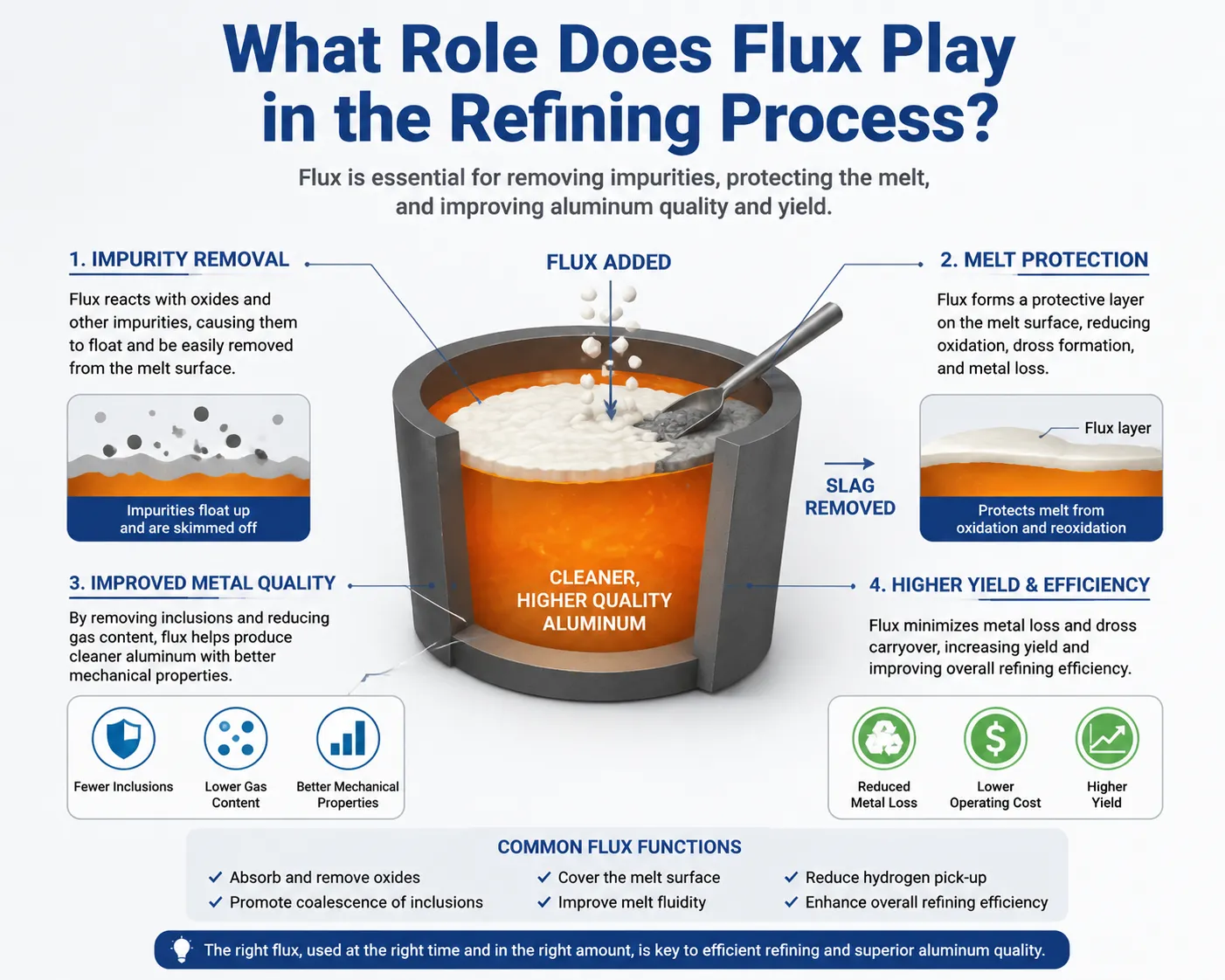
Senyawa fluks, yang umumnya terdiri dari campuran garam klorida dan fluorida, bereaksi secara kimiawi dengan inklusi oksida dan unsur-unsur jejak tertentu dalam cairan logam, mengubahnya menjadi senyawa yang kemudian mengapung ke permukaan sebagai dross yang dapat dibuang atau menggumpal menjadi partikel yang lebih besar yang mengendap dan kemudian disaring. Menyuntikkan fluks secara langsung ke dalam cairan logam melalui poros berputar, alih-alih hanya menaburkannya di permukaan, secara drastis meningkatkan kontak antara partikel fluks dan inklusi yang tersebar di seluruh volume cairan logam.
Kami telah mengukur kandungan inklusi sebelum dan sesudah perlakuan menggunakan metode pengujian filtrasi standar di berbagai fasilitas pelanggan, dan kombinasi dispersi mekanis dari gerakan rotasi ditambah injeksi fluks yang tepat secara konsisten memberikan hasil yang lebih baik dibandingkan dengan degassing hanya dengan gas atau aplikasi fluks permukaan saja. Fasilitas yang menggunakan injeksi fluks terintegrasi melalui rotor umumnya mengalami pengurangan inklusi dalam kisaran 60–85%, dibandingkan dengan pengurangan 30–50% dari pengolahan gas tanpa bantuan fluks.
| Pendekatan Pengobatan | Pengurangan Inklusi | Reduksi Hidrogen | Aplikasi Terbaik |
|---|---|---|---|
| Hanya gas, tanpa fluks | 30-50% | Bagus. | Sisa bahan yang bersih, lelehan yang lebih sedikit terkontaminasi |
| Fluks permukaan, tanpa injeksi | 40-55% | N/A | Penghilangan kotoran dasar |
| Gas rotari dengan injeksi fluks | 60-85% | Bagus. | Sisa bahan daur ulang, bahan baku tungku yang terkontaminasi |
| Gas rotari dengan penyesuaian fluks dan kecepatan yang dioptimalkan | 70-90% | Luar biasa | Persyaratan pengecoran dengan integritas tinggi |
Pemilihan komposisi kimia fluks yang tepat sangatlah penting dan bervariasi tergantung pada komposisi paduan serta profil kontaminasi spesifik. Secara umum, kami menyarankan pelanggan untuk bekerja sama dengan pemasok fluks dan penyedia peralatan secara bersamaan, alih-alih memperlakukan hal ini sebagai keputusan pembelian yang terpisah, karena ketidaksesuaian antara komposisi kimia fluks dan parameter injeksi akan menyebabkan pemborosan bahan tanpa mencapai hasil pemurnian yang diharapkan.
Bahan Rotor dan Poros Manakah yang Paling Tahan Lama dalam Aluminium Cair?
Keausan komponen merupakan sumber utama biaya operasional berkelanjutan dari peralatan ini, dan pemilihan bahan untuk rotor dan poros menentukan seberapa sering penggantian perlu dilakukan.
Grafit tetap menjadi bahan standar baik untuk kepala rotor maupun porosnya berkat biayanya yang terjangkau, ketahanan yang baik terhadap guncangan termal, serta stabilitas kimia yang memadai dalam aluminium cair. Namun, grafit tanpa lapisan akan mengalami erosi secara bertahap akibat oksidasi dan keausan mekanis yang disebabkan oleh rotasi dan aliran gas, sehingga biasanya memerlukan penggantian rotor setiap 30–80 siklus pengolahan, tergantung pada intensitas operasi dan komposisi kimia logam cair.
Rotor grafit berlapis keramik, yang dilapisi dengan lapisan pelindung boron nitrida atau keramik sejenis di atas struktur grafit dasarnya, dapat memperpanjang masa pakai secara signifikan dengan mengurangi oksidasi dan erosi kimia. Kami telah memantau data masa pakai yang menunjukkan bahwa rotor berlapis biasanya bertahan selama 100–200 siklus sebelum perlu diganti, kira-kira dua hingga tiga kali lipat masa pakai unit tanpa lapisan, meskipun dengan biaya pembelian yang secara proporsional lebih tinggi.
| Jenis Bahan | Umur Pakai Umum (Siklus Perawatan) | Biaya Relatif | Aplikasi Terbaik |
|---|---|---|---|
| Grafit standar, tanpa lapisan | 30–80 siklus | Lebih rendah | Operasi dengan volume lebih rendah, aplikasi yang mengutamakan efisiensi biaya |
| Grafit berlapis keramik | 100–200 siklus | Sedang hingga tinggi | Produksi dalam skala besar, mengurangi waktu henti akibat pergantian produksi |
| Grafit yang diperkuat dengan silikon karbida | 150–250 siklus | Lebih tinggi | Operasi perawatan intensitas tinggi yang berkelanjutan |
Kami selalu menyarankan pelanggan untuk menghitung biaya per siklus perawatan daripada membandingkan harga pembelian rotor secara langsung, karena rotor berlapis yang harganya dua kali lipat namun tahan tiga kali lebih lama justru mengurangi biaya operasional keseluruhan meskipun harga satunya lebih tinggi. Perhitungan ini menjadi semakin penting ketika memperhitungkan biaya tenaga kerja dan waktu henti produksi yang terkait dengan penggantian rotor, yang dapat dikurangi oleh unit berlapis hanya dengan mengurangi frekuensi penggantian.
Bagaimana Cara Menentukan Kecepatan Rotor dan Laju Aliran Gas untuk Ukuran Batch yang Berbeda-beda?
Untuk menentukan parameter-parameter ini dengan tepat, diperlukan pemahaman mengenai hubungan antara volume lelehan, target waktu pengolahan, dan kapasitas peralatan—hal yang sering menjadi kendala bagi operator yang beralih dari sistem lance yang lebih sederhana tanpa pelatihan yang memadai.
Volume lelehan yang lebih besar umumnya memerlukan waktu perlakuan yang lebih lama pada kecepatan rotor yang sama, atau diameter rotor yang lebih besar yang mampu mendispersikan gas ke seluruh volume lelehan yang lebih luas dalam jangka waktu yang sebanding. Hanya meningkatkan laju aliran gas tanpa menyesuaikan kecepatan dan ukuran rotor secara proporsional seringkali justru menghasilkan gelembung yang lebih besar yang naik lebih cepat tanpa waktu transfer hidrogen yang memadai, sehingga menghilangkan tujuan dari pendekatan rotari tersebut.
| Ukuran Batch Peleburan | Diameter Rotor yang Direkomendasikan | Kecepatan Rotor yang Umum | Laju Aliran Gas yang Umum | Perkiraan Waktu Perawatan |
|---|---|---|---|---|
| 300–500 kg | 100–120 mm | 300–400 putaran per menit | 8–12 L/menit | 8–10 menit |
| 500–1.000 kg | 120–150 mm | 300–450 putaran per menit | 10–18 L/menit | 10–14 menit |
| 1–3 ton | 150–200 mm | 350–450 putaran per menit | 15–25 L/menit | 12–18 menit |
| Di atas 3 ton | 200 mm ke atas, atau sistem rotor ganda | 300–400 putaran per menit | 20–35 L/menit | 15–25 menit |
Kami menyesuaikan rekomendasi dasar ini berdasarkan hasil pengukuran aktual dari komposisi kimia lelehan dan kondisi tungku masing-masing pelanggan, karena kualitas bahan daur ulang dan tingkat hidrogen awal yang umum bervariasi cukup signifikan antar fasilitas sehingga pendekatan yang murni berdasarkan rumus terkadang memerlukan kalibrasi berdasarkan kondisi lapangan selama tahap komisioning.
Masalah Pemeliharaan Apa yang Paling Sering Menyebabkan Waktu Henti?
Setelah melakukan pemeliharaan terhadap peralatan ini di berbagai fasilitas pelanggan, kami menyadari bahwa hanya segelintir masalah yang sama yang menjadi penyebab sebagian besar panggilan terkait waktu henti tak terduga yang kami terima.
Erosi rotor dan poros yang melampaui batas operasi yang aman merupakan kebutuhan pemeliharaan yang paling dapat diprediksi, dan fasilitas yang memantau jumlah siklus penggunaan serta mengganti komponen secara proaktif berdasarkan masa pakai yang diperkirakan dapat menghindari sebagian besar situasi darurat. Fasilitas yang terus mengoperasikan komponen hingga terjadi kegagalan yang terlihat biasanya menghadapi penghentian produksi yang tidak direncanakan pada saat yang paling tidak tepat, umumnya di tengah shift saat tungku penuh dengan logam cair yang menunggu proses pengolahan.
Masalah pada sistem pengendalian aliran gas, termasuk pengukur aliran yang tersumbat atau segel yang rusak sehingga memungkinkan masuknya udara ke dalam aliran gas yang seharusnya inert, menyebabkan penurunan kinerja yang tidak terlalu mencolok dan lebih sulit didiagnosis dibandingkan kegagalan komponen yang jelas-jelas terlihat. Kami telah mengunjungi lebih dari satu fasilitas di mana kinerja degassing telah menurun secara perlahan selama berminggu-minggu akibat segel yang rusak, dengan operator tidak menyadari penyebab utamanya hingga kami mengidentifikasinya selama kunjungan servis.
Keausan motor penggerak dan kopling, terutama pada sistem yang beroperasi secara terus-menerus dalam beberapa shift, memerlukan pelumasan bantalan dan pemeriksaan kopling secara berkala—hal yang sering terabaikan ketika jadwal pemeliharaan lebih berfokus pada komponen yang mengalami keausan yang terendam dalam logam daripada komponen penggerak mekanis di atas garis lelehan.
| Masalah Pemeliharaan | Frekuensi Umum | Pendekatan Pencegahan |
|---|---|---|
| Erosi rotor/poros | Berlangsung terus-menerus, dapat diprediksi dengan pemantauan siklus | Penggantian proaktif berdasarkan penghitungan siklus, bukan berdasarkan kegagalan |
| Kerusakan segel aliran gas | Secara bertahap, membutuhkan waktu berbulan-bulan untuk dikembangkan | Pemeriksaan dan penggantian segel sesuai jadwal |
| Keausan bantalan motor penggerak | Biasanya setiap 6–12 bulan | Pelumasan rutin sesuai jadwal yang ditetapkan pabrikan |
| Masalah pada mekanisme pengangkat hidraulik | Sesekali | Pemeriksaan tingkat cairan, pemeriksaan segel |
| Penyumbatan pada pengumpan fluks | Sering terjadi jika kelembapan fluks tidak dikendalikan | Penyimpanan fluks yang tepat, kondisi kering |
Bagaimana Peralatan Ini Mempengaruhi Metrik Kualitas Pengecoran Secara Keseluruhan?
Selain angka-angka langsung terkait hidrogen dan pengurangan inklusi yang telah dibahas sebelumnya, penerapan proses degassing rotari yang tepat cenderung menghasilkan peningkatan kualitas pada tahap hilir yang seringkali tidak diantisipasi oleh para pengambil keputusan pembelian hingga mereka melihat data dari produksi mereka sendiri.
Konsistensi sifat mekanis meningkat secara signifikan begitu hidrogen yang menyebabkan porositas dapat dikendalikan dengan andal, karena rongga internal yang tersebar menciptakan titik-titik konsentrasi tegangan yang mengurangi umur kelelahan dan kekuatan tarik secara tak terduga. Fasilitas yang memproduksi komponen struktural atau yang sangat penting bagi keselamatan sering melaporkan distribusi sifat mekanik yang lebih seragam di seluruh batch produksi setelah menerapkan protokol degassing rotari yang konsisten, dibandingkan dengan variabilitas yang lebih luas yang biasanya terjadi akibat penanganan lance yang tidak konsisten.
Kinerja pemesinan juga ikut meningkat, karena porositas pada permukaan dan di bawah permukaan yang terungkap selama operasi pemesinan menyebabkan munculnya bagian yang ditolak dan masalah keausan perkakas, yang akar penyebabnya dapat ditelusuri hingga proses penghilangan gas yang tidak memadai. Beberapa pelanggan yang memproduksi komponen aluminium yang diproses secara presisi telah melaporkan penurunan yang terukur pada limbah pada tahap pemesinan setelah memperketat pengendalian proses degassing, sebuah hubungan yang tidak selalu jelas hingga seseorang benar-benar menelusuri akar penyebab penolakan tersebut kembali melalui proses produksi.
Kualitas permukaan pada permukaan hasil pengecoran, yang sangat relevan bagi produk aluminium arsitektural dan dekoratif, akan meningkat jika inklusi oksida dihilangkan dengan benar melalui perlakuan fluks yang efektif yang dikombinasikan dengan proses degassing, karena inklusi yang menembus permukaan menimbulkan cacat yang terlihat yang memerlukan pekerjaan penyempurnaan tambahan atau bahkan mengakibatkan penolakan langsung pada aplikasi yang sangat mengutamakan penampilan.
Memilih Ukuran dan Konfigurasi Sistem yang Tepat untuk Operasi Anda
Menyesuaikan kapasitas peralatan dengan kebutuhan produksi yang sebenarnya dapat mencegah terjadinya kinerja yang kurang optimal akibat sistem yang berkapasitas terlalu kecil, sekaligus menghindari pengeluaran yang tidak perlu akibat kapasitas yang berlebihan yang tidak pernah dimanfaatkan.
Kami memandu pelanggan melalui beberapa pertanyaan sebelum merekomendasikan konfigurasi peralatan tertentu. Berapa ukuran batch tipikal yang diproses per siklus perlakuan? Berapa tingkat hidrogen awal yang biasanya dihasilkan oleh tungku, berdasarkan kualitas sisa logam dan metode peleburan? Berapa tingkat hidrogen target yang dibutuhkan oleh aplikasi akhir, mengingat spesifikasi pengecoran untuk industri dirgantara dan pengecoran tahan tekanan sangat berbeda dari persyaratan pengecoran untuk keperluan umum? Berapa banyak siklus perlakuan yang perlu dilakukan per shift, karena hal ini memengaruhi apakah satu stasiun rotor sudah cukup atau apakah konfigurasi dua stasiun diperlukan untuk mempertahankan throughput produksi?
Sistem rotor tunggal mampu menangani sebagian besar operasi pengecoran skala kecil hingga menengah dengan memadai, dengan memproses satu batch pada satu waktu, sementara operator memindahkan rakitan rotor antara posisi tungku dan wadah tuang sesuai kebutuhan. Operasi dengan volume yang lebih tinggi terkadang diuntungkan oleh stasiun pengolahan khusus yang terintegrasi dalam jalur aliran logam, sehingga memungkinkan pengolahan berkelanjutan tanpa perlu penyesuaian posisi per batch seperti yang diperlukan pada sistem rotor portabel.
| Profil Produksi | Konfigurasi yang Disarankan | Tingkat Investasi yang Umum |
|---|---|---|
| Pengecoran kecil, kurang dari 20 siklus per hari | Unit rotor portabel tunggal | Lebih rendah |
| Pabrik pengecoran skala menengah, 20–50 siklus per hari | Unit tunggal dengan posisi tetap yang dilengkapi kemampuan penggantian rotor secara cepat | Sedang |
| Produksi skala besar, lebih dari 50 siklus per hari | Sistem rotor ganda atau pengolahan berkelanjutan secara in-line | Lebih tinggi |
| Aplikasi khusus/dirgantara | Satu unit dengan pemantauan presisi dan pencatatan data | Sedang hingga tinggi, berfokus pada pengendalian mutu |
Pertanyaan yang Sering Diajukan
Gas inert apa yang paling cocok digunakan untuk proses degassing aluminium dengan metode injeksi fluks rotari?
Nitrogen merupakan pilihan yang paling umum karena biayanya yang lebih rendah dan kinerjanya yang memadai untuk sebagian besar aplikasi, sementara argon menawarkan efisiensi penghilangan hidrogen yang sedikit lebih baik berkat karakteristik kelarutannya yang lebih rendah, namun dengan biaya gas yang lebih tinggi. Sebagian besar aplikasi pengecoran umum menggunakan nitrogen, sedangkan argon disisihkan untuk persyaratan pengecoran dengan integritas tinggi di mana perbedaan kinerjanya sebanding dengan biayanya.
Seberapa sering rotor dan poros harus diganti?
Hal ini bergantung pada jenis bahan dan intensitas pengoperasian, namun grafit tanpa lapisan biasanya perlu diganti setiap 30–80 siklus pengolahan, sedangkan versi yang dilapisi keramik dapat bertahan hingga 100–200 siklus. Kami menyarankan untuk mencatat jumlah siklus aktual per komponen daripada hanya mengandalkan waktu kalender, karena intensitas penggunaan bervariasi secara signifikan antar fasilitas.
Apakah sistem degassing rotari dapat digunakan untuk semua paduan aluminium?
Ya, mekanisme degassing dasar berlaku untuk seluruh jenis paduan aluminium cor, meskipun pemilihan komposisi kimia fluks perlu disesuaikan berdasarkan komposisi paduan yang spesifik, terutama untuk paduan yang mengandung magnesium atau unsur-unsur lain yang bereaksi secara berbeda dengan senyawa fluks standar.
Apa yang menyebabkan hasil degassing tidak konsisten dari satu batch ke batch lainnya?
Penyebab umum meliputi komponen rotor yang aus sehingga tidak lagi menghasilkan dispersi gelembung yang tepat, aliran gas yang tidak konsisten akibat masalah pada sistem kendali, tingkat hidrogen awal yang bervariasi akibat kualitas bahan baku yang tidak konsisten, serta variasi suhu lelehan yang memengaruhi kelarutan gas dan kinetika perlakuan. Kami merekomendasikan dilakukannya pemecahan masalah secara sistematis dengan memulai dari pemeriksaan kondisi peralatan sebelum menyimpulkan bahwa masalahnya terletak pada parameter proses.
Apakah proses degassing rotari diperlukan jika saya hanya memproduksi coran pasir, bukan komponen yang kedap tekanan?
Meskipun coran pasir dapat mentoleransi porositas yang sedikit lebih tinggi dibandingkan aplikasi yang menuntut kedap tekanan, hidrogen yang tidak terkendali tetap memengaruhi sifat mekanis, kualitas permukaan, dan kinerja pemesinan, bahkan pada aplikasi yang tidak kritis. Sebagian besar fasilitas berpendapat bahwa peningkatan kualitas tersebut membenarkan dilakukannya perlakuan bahkan untuk coran guna umum, meskipun tingkat hidrogen yang ditargetkan dapat lebih longgar dibandingkan persyaratan untuk komponen dirgantara atau hidraulik.
Berapa lama waktu yang dibutuhkan untuk satu siklus pengolahan degassing rotari pada umumnya?
Waktu perlakuan biasanya berkisar antara 8 hingga 20 menit, tergantung pada ukuran batch, kadar hidrogen awal, kadar hidrogen akhir yang ditargetkan, serta kecepatan dan desain rotor. Pada sebagian besar aplikasi pengecoran standar, proses perlakuan dapat diselesaikan dalam waktu 10–15 menit untuk ukuran batch yang umum.
Apa perbedaan antara pengaruh kecepatan rotor terhadap proses degassing dibandingkan dengan proses pencampuran fluks?
Proses degassing diuntungkan oleh kecepatan rotor yang stabil dan sedang, yang menghasilkan dispersi gelembung halus tanpa gangguan permukaan yang berlebihan, sementara proses pencampuran fluks terkadang diuntungkan oleh profil kecepatan yang sedikit berbeda untuk memastikan distribusi partikel fluks padat yang merata di seluruh volume lelehan. Sistem yang menangani kedua fungsi tersebut sering kali menggunakan profil kecepatan yang menyeimbangkan kedua tujuan ini, alih-alih hanya mengoptimalkan untuk satu fungsi saja.
Apakah saya bisa mengukur kadar hidrogen dalam lelehan saya tanpa mengirimkan sampel ke laboratorium eksternal?
Ya, alat pengukur hidrogen portabel yang menggunakan konduktivitas termal atau prinsip pengukuran in-situ serupa memungkinkan pemeriksaan kadar hidrogen secara real-time langsung di tungku, sehingga memberikan umpan balik langsung mengenai efektivitas proses tanpa harus menunggu hasil laboratorium eksternal.
Apakah proses degassing rotari dapat menghilangkan semua jenis kotoran dari aluminium cair?
Tidak, proses degassing rotari dengan injeksi fluks terutama ditujukan untuk mengatasi gas hidrogen terlarut serta inklusi oksida atau non-logam yang mengapung. Proses ini tidak menghilangkan pengotor logam terlarut atau menyesuaikan komposisi kimia paduan; hal tersebut memerlukan proses metalurgi yang berbeda jika penyesuaian komposisi memang diperlukan.
Tindakan pencegahan keselamatan apa yang paling penting saat mengoperasikan peralatan injektor fluks rotari?
Alat pelindung diri yang sesuai untuk melindungi dari percikan logam cair, penempatan mekanisme pengangkat yang aman guna mencegah kontak tak disengaja antara rotor dengan logam cair selama periode tidak beroperasi, ventilasi yang memadai untuk penghisapan asap fluks, serta pemeriksaan rutin terhadap poros dan rotor untuk mendeteksi kerusakan yang dapat menyebabkan kegagalan mekanis mendadak selama pengoperasian, merupakan pertimbangan keselamatan utama yang kami tekankan selama pelatihan pelanggan.
Refleksi Akhir dari Pengalaman Lapangan Kami
Pengalaman bertahun-tahun dalam pemasangan, pemeliharaan, dan pemecahan masalah sistem injektor fluks rotari di berbagai pabrik pengecoran aluminium dengan skala yang beragam telah mengajarkan kepada kami bahwa kemampuan peralatan hanya akan memberikan nilai tambah jika dipadukan dengan disiplin operasional yang tepat. Pabrik yang memantau jumlah siklus, mengganti komponen yang aus secara proaktif, dan meluangkan waktu untuk mengkalibrasi kecepatan rotor serta aliran gas sesuai dengan kondisi peleburan spesifik mereka secara konsisten mencapai angka pengurangan hidrogen dan inklusi yang membenarkan investasi pada peralatan tersebut. Sebaliknya, fasilitas yang memperlakukan sistem ini sebagai alat sederhana yang hanya dinyalakan atau dimatikan tanpa memperhatikan detail operasional tersebut sering kali mendapatkan hasil yang mengecewakan; hasil tersebut sama sekali tidak berkaitan dengan kualitas peralatan, melainkan sepenuhnya disebabkan oleh kelemahan dalam pengendalian proses.
Rekomendasi kami bagi setiap fasilitas yang mengevaluasi teknologi ini tetap didasarkan pada prinsip yang sama yang kami terapkan dalam semua konsultasi peralatan kami: pahami tingkat hidrogen awal yang sebenarnya dan persyaratan target Anda sebelum menentukan ukuran dan konfigurasi peralatan, lakukan investasi dalam pelatihan operator yang memadai bersamaan dengan pembelian peralatan, serta pantau keausan komponen secara sistematis, bukan secara reaktif. Proses degassing rotari yang dilakukan dengan benar dapat secara signifikan meningkatkan kualitas hasil pengecoran, namun hal ini hanya akan tercapai jika peralatan dioperasikan dengan perhatian terhadap detail yang sama seperti pada setiap tahap presisi lainnya dalam proses pengecoran.