

Ein ordnungsgemäß betriebener Rotationsflussinjektor reduziert den Gehalt an gelöstem Wasserstoff in geschmolzenem Aluminium innerhalb von 10 bis 15 Minuten nach der Behandlung von den typischen Ofenwerten von 0,3–0,6 ml/100 g auf 0,10–0,15 ml/100 g, und entfernt gleichzeitig 60–85% an nichtmetallischen Einschlüssen, wenn er mit einer geeigneten Flussmittelzusammensetzung kombiniert wird. Das ist die praktische Schlussfolgerung, die wir aus dem Betrieb und der Fehlerbehebung dieser Anlage in Dutzenden von Aluminiumgießereien gezogen haben, und deshalb hat die Rotationsentgasung ältere, auf Lanzen und Tabletten basierende Verfahren in jedem Betrieb, der Wert auf Gussqualität legt, weitgehend abgelöst.
Falls für Ihr Projekt der Einsatz eines rotierenden Flussmittel-Einspritzsystems erforderlich ist, können Sie Kontaktieren Sie uns für ein kostenloses Angebot.
Was ist ein Rotations-Flussmittelinjektor und wie funktioniert er eigentlich?
Ein Rotationsflussinjektor, der manchmal auch als Rotationsentgaser oder Rotationsimpellersystem bezeichnet wird, besteht aus einer rotierenden Welle mit einem speziell konstruierten Rotorkopf, der in geschmolzenes Aluminium eingetaucht ist. Inertgas, typischerweise Stickstoff oder Argon, strömt durch die hohle Welle nach unten und tritt durch Öffnungen im Rotor aus. Durch die Drehbewegung des Rotors wird das austretende Gas in extrem feine Bläschen zerteilt, wodurch sich die für die Wasserstoffaufnahme verfügbare Oberfläche im Vergleich zum einfachen Einblasen von Gas durch eine stationäre Lanze drastisch vergrößert.
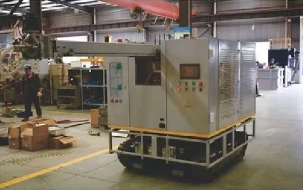
Wir haben diesen Mechanismus während der Entwicklungstests unter kontrollierten Bedingungen mithilfe transparenter Beobachtungsvorrichtungen beobachtet, und der Unterschied in der Blasengröße zwischen der rotierenden Dispersion und der statischen Lanzeninjektion ist auffällig. Eine Lanze erzeugt Blasen mit einem Durchmesser von oft mehreren Millimetern, die schnell durch die Schmelze aufsteigen und nur eine begrenzte Verweildauer haben. Ein gut konstruierter Rotor erzeugt häufig Blasen mit einem Durchmesser von unter einem Millimeter, die über die gesamte Behandlungszone verteilt sind und eine wesentlich längere Verweildauer haben, bevor sie die Oberfläche erreichen.
Dieser physikalische Unterschied wirkt sich unmittelbar auf die Effizienz der Behandlung aus. In geschmolzenem Aluminium gelöster Wasserstoff diffundiert in Richtung der Blasen mit niedrigem Partialdruck und wird von diesen beim Aufsteigen mitgerissen. Kleinere Blasen mit größerer Gesamtoberfläche und längerer Kontaktzeit entziehen pro verbrauchter Gaseinheit einfach mehr Wasserstoff – und genau das ist der Grund, warum Rotationssysteme die Lanzenentgasung sowohl hinsichtlich der Geschwindigkeit als auch der Gaseffizienz übertreffen.
Wesentliche Komponenten, die Käufer kennen sollten
Das System umfasst nicht nur den Rotor und die Welle, sondern auch eine Gasversorgungs- und Durchflussregeleinheit, einen Motor und einen Antriebsmechanismus zur Steuerung der Rotordrehzahl, eine Tragkonstruktion, die die vertikale Positionierung in die Schmelze hinein und wieder heraus ermöglicht, sowie häufig einen Flussmitteleinspritzmechanismus, der pulverförmiges oder körniges Flussmittel zusammen mit dem Inertgasstrom einbringt.
| Komponente | Funktion | Typisches Material |
|---|---|---|
| Rotorkopf | Verteilt Gas durch Rotation in feine Bläschen | Graphit, keramikbeschichtetes Graphit |
| Welle | Fördert Gas von der Quelle zum Rotor und überträgt die Drehbewegung | Graphit, hochreines Graphit mit Schutzbeschichtung |
| Antriebsmotor | Regelt die Drehzahl | Elektromotor mit Frequenzumrichter |
| Gasdurchflussregler | Regelt den Durchfluss und den Druck des Inertgases | Edelstahl, Präzisionsdurchflussmesser |
| Stütz- und Hebemechanismus | Bringt die Rotorbaugruppe in die Schmelze ein und ermöglicht deren Entnahme zu Wartungszwecken | Stahlrahmen, hydraulischer oder motorbetriebener Aufzug |
| Flussmittelzufuhrsystem (optional) | Führt während der Behandlung feste Flussmittelverbindungen ein | Schneckendosierer oder pneumatische Einspritzung |
Warum muss Aluminium vor dem Gießen entgast werden?
Jeder, der schon einmal ein Gussteil aufgeschnitten und dabei verstreute Poren entdeckt hat, weiß, worum es hier in der Praxis geht, doch die zugrunde liegende Chemie erklärt, warum dieses Problem ohne aktives Eingreifen im Grunde unvermeidbar ist.
Geschmolzenes Aluminium nimmt Wasserstoff leicht aus der Feuchtigkeit in der Ofenatmosphäre, aus hydratisierten Verbindungen auf den Oberflächen von Altmetall sowie aus Verbrennungsnebenprodukten in gasbefeuerten Öfen auf. Die Wasserstofflöslichkeit in Aluminium sinkt stark, wenn das Metall abkühlt und erstarrt; sie ist in festem Aluminium etwa zwanzigmal geringer als im flüssigen Zustand bei Schmelztemperatur. Diese Löslichkeitslücke bedeutet, dass gelöster Wasserstoff, der in der flüssigen Schmelze vollkommen stabil war, während der Erstarrung nirgendwo hin kann, außer dass er Gasblasen bildet, die in der Gussstruktur eingeschlossen werden.
Diese eingeschlossenen Blasen zeigen sich als Porosität, die von mikroskopisch kleinen, ohne Vergrößerung unsichtbaren Löchern bis hin zu sichtbaren Hohlräumen reicht, die die strukturelle Integrität und die Oberflächenqualität nach der Bearbeitung beeinträchtigen. Bei druckdichten Gussteilen wie Getriebegehäusen für Kraftfahrzeuge oder Hydraulikkomponenten führt bereits geringfügige Porosität bei Druckprüfungen zu Funktionsausfällen, sodass die Entgasung nicht nur eine Qualitätsanforderung, sondern eine zwingende Produktionsvoraussetzung ist.
Wir haben Ausschussdaten aus mehreren Kundenbetrieben vor und nach der Einführung geeigneter Rotationsentgasungsverfahren ausgewertet, und dabei zeigt sich immer wieder dasselbe Muster: Die porositätsbedingten Ausschussquoten sinken in der Regel von 8–15% auf 2–4%, sobald die Behandlungsparameter korrekt auf die jeweilige Legierung und die jeweilige Gussgeometrie abgestimmt sind.
| Wasserstoffgehalt (ml/100 g) | Risikostufe der Porosität | Typische Anwendungsbereiche |
|---|---|---|
| Über 0,30 | Hohes Risiko | Nicht geeignet für druckdichte oder kritische Gussteile |
| 0.20-0.30 | Mäßiges Risiko | Allzweckgussteile, unkritische Anwendungen |
| 0.15-0.20 | Geringes bis mittleres Risiko | Standard-Strukturgussteile |
| 0.10-0.15 | Geringes Risiko | Druckdichte Gussteile, Komponenten für die Luft- und Raumfahrt |
| Weniger als 0,10 | Sehr geringes Risiko | Hochzuverlässige Komponenten für die Luft- und Raumfahrt, sicherheitskritische Bauteile |
Wie schneidet das Rotationsspritzverfahren im Vergleich zur Lanzenentgasung und anderen Verfahren ab?
Käufer, die sich über diese Anlage informieren, bitten uns fast immer, den Preisaufschlag gegenüber einfacheren Alternativen zu begründen – und das ist eine berechtigte Frage, da Lanzen-Entgasungssysteme nur einen Bruchteil einer Rotationsanlage kosten.
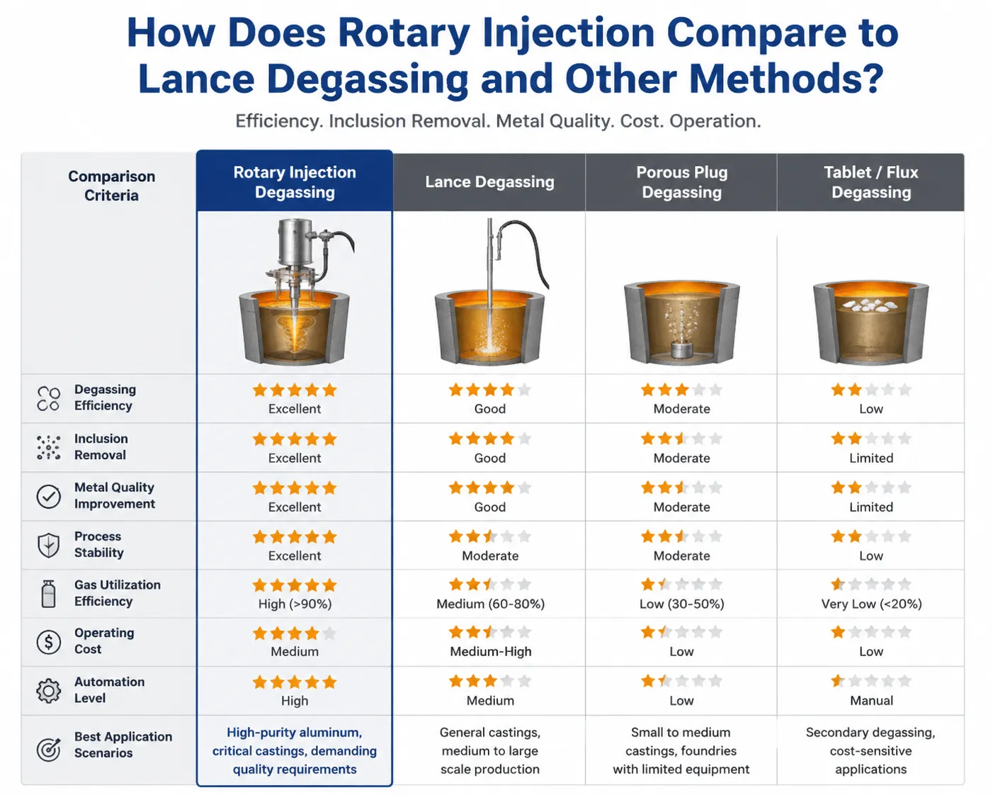
Bei der Lance-Entgasung wird Inertgas ohne mechanische Dispergierung durch ein untergetauchtes Rohr oder einen porösen Stopfen geleitet, wobei die Wasserstoffentfernung ausschließlich durch den natürlichen Blasenanstieg erfolgt. Dieses Verfahren ist kostengünstig und mechanisch einfach, liefert jedoch messbar schlechtere Ergebnisse, da die größeren Blasen und die kürzere Kontaktzeit mit der Schmelze die Effizienz der Wasserstoffentfernung erheblich verringern.
Die Entgasung von Tabletten mithilfe fester Verbindungen, die bei ihrer Zersetzung in der Schmelze Gas freisetzen, bietet den Vorteil, dass keine Investitionen in Anlagen erforderlich sind, weist jedoch im Vergleich zur kontrollierten Rotationsinjektion den Nachteil eines unregelmäßigen Zeitablaufs der Gasfreisetzung sowie allgemein schlechterer Gesamtergebnisse auf.
Bei der Vakuumentgasung, die vor allem bei der Verarbeitung von Stahl und Speziallegierungen zum Einsatz kommt, werden gelöste Gase entfernt, indem der atmosphärische Druck über der Schmelze gesenkt wird, anstatt Gas durch die Schmelze zu leiten. Dieses Verfahren ist zwar sehr effektiv, erfordert jedoch wesentlich teurere Anlagen und einen höheren Zeitaufwand, was es für die meisten Aluminiumgießereien und Gussbetriebe mit hohen Produktionsvolumina unpraktisch macht.
| Entgasungsverfahren | Effizienz der Wasserstoffentfernung | Behandlung Zeit | Ausrüstungskosten | Gasverbrauch |
|---|---|---|---|---|
| Lanze/poröser Stopfen | Gering bis mäßig | 20–30 Minuten | Niedrig | Hohes Ergebnis pro Einheit |
| Entgasung von Tabletten | Niedrig, uneinheitlich | 15–25 Minuten | Sehr niedrig | k. A. (feste Verbindung) |
| Rotierende Flussinjektion | Hoch | 8–15 Minuten | Mäßig bis hoch | Maßvolle, effiziente Nutzung |
| Vakuum-Entgasung | Sehr hoch | 20–40 Minuten | Sehr hoch | Ein einfaches, aber komplexes System |
Unsere eigenen Feldvergleiche, die bei Kunden durchgeführt wurden, die bereit waren, beide Verfahren an geteilten Chargen aus derselben Schmelze zu testen, zeigten durchweg, dass Rotationssysteme die angestrebten Wasserstoffwerte in etwa der Hälfte der Behandlungszeit im Vergleich zu Lanzenverfahren erreichten, wobei aufgrund der deutlich verbesserten Übertragungsleistung ein vergleichbares oder geringeres Gesamtgasvolumen verbraucht wurde.
Welche Effizienz bei der Wasserstoffentfernung können Käufer tatsächlich erwarten?
In den technischen Datenblättern der Hersteller werden manchmal idealisierte Leistungswerte angegeben, die nicht die tatsächlichen Gegebenheiten in einer Gießerei widerspiegeln, wo die Schrottqualität und die Ofenbedingungen schwanken. Wir ziehen es vor, Spannen anzugeben, die auf dokumentierten Praxisergebnissen basieren, anstatt auf Laborversuchen unter optimalen Bedingungen.
Die erreichbaren Endwerte für den Wasserstoffgehalt hängen von der anfänglichen Wasserstoffkonzentration, der Behandlungsdauer, der Rotordrehzahl, dem Gasdurchsatz und der gleichmäßigen Schmelztemperatur während der Behandlung ab. Ein gut abgestimmtes Rotationssystem, das eine Schmelze mit einem Wasserstoffgehalt von etwa 0,40 ml/100 g behandelt, senkt diesen Wert in der Regel innerhalb eines 10- bis 12-minütigen Behandlungszyklus bei geeigneter Rotordrehzahl auf 0,10 bis 0,15 ml/100 g.
| Rotordrehzahl (RPM) | Gasdurchsatz | Typische Behandlungsdauer für das Zielniveau | Anmerkungen |
|---|---|---|---|
| 150-250 | Niedrig | 15–20 Minuten | Schonende Behandlung, minimale Turbulenzen, geringerer Wirkungsgrad |
| 300-400 | Mäßig | 10–14 Minuten | Ausgewogene Leistung für die meisten Anwendungen |
| 400-500 | Mäßig bis hoch | 8–12 Minuten | Eine schnellere Behandlung erfordert eine gute Rotorkonstruktion, um übermäßige Oberflächenstörungen zu vermeiden. |
| Über 500 | Hoch | Geringfügige Verbesserung | Gefahr der Wirbelbildung, durch die Oberflächenoxid in die Schmelze gezogen wird; wird generell nicht empfohlen |
Wir weisen unsere Kunden darauf hin, nicht davon auszugehen, dass eine höhere Rotordrehzahl immer eine schnellere oder bessere Entgasung bedeutet. Eine zu hohe Drehzahl erzeugt einen Wirbel, der den Oberflächenoxidfilm und Luftgase zurück in die Schmelze ziehen kann, was dem Behandlungsziel tatsächlich entgegenwirkt. Jedes von uns in Betrieb genommene System wird speziell auf die Ofengeometrie und die typische Chargengröße abgestimmt, da eine Drehzahl, die in einem 500-kg-Halteofen gut funktioniert, in einer 2-Tonnen-Anlage mit anderen Schmelztiefen- und Oberflächencharakteristika Probleme verursachen kann.
Welche Rolle spielt Flussmittel im Veredelungsprozess?
Die Entgasung dient der Entfernung von gelöstem Wasserstoff, doch nichtmetallische Einschlüsse, Oxidschichten und bestimmte unerwünschte Elemente lassen sich nur mit chemischer Unterstützung durch Flussmittelverbindungen wirksam beseitigen – und genau hier kommt die Bezeichnung “Flussmittelinjektor” im Namen dieser Anlage ins Spiel.
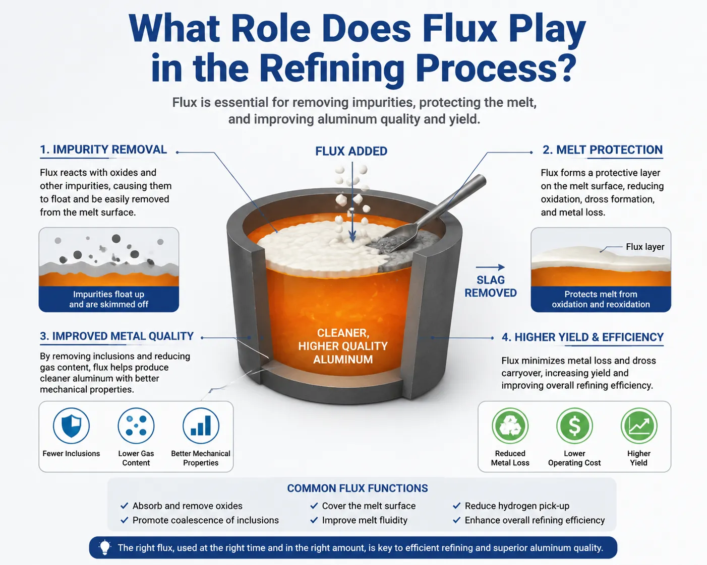
Flussmittelverbindungen, die in der Regel auf Mischungen aus Chlorid- und Fluoridsalzen basieren, reagieren chemisch mit Oxideinschlüssen und bestimmten Spurenelementen in der Schmelze und wandeln diese in Verbindungen um, die entweder als entfernbare Krätze an die Oberfläche aufsteigen oder zu größeren Partikeln zusammenwachsen, die sich absetzen und abgeschöpft werden. Das direkte Einbringen des Flussmittels in die Schmelze durch die rotierende Welle – anstatt es lediglich auf die Oberfläche zu streuen – verbessert den Kontakt zwischen den Flussmittelpartikeln und den im gesamten Schmelzvolumen verteilten Einschlüssen erheblich.
Wir haben den Einschlussgehalt vor und nach der Behandlung mithilfe standardmäßiger Filtrationsprüfverfahren in mehreren Kundenanlagen gemessen, und die Kombination aus mechanischer Dispersion durch Rotationsbewegung und ordnungsgemäßer Flussmittelinjektion erzielt durchweg bessere Ergebnisse als entweder die Entgasung ausschließlich mit Gas oder die alleinige Anwendung von Oberflächenflussmittel. Anlagen, die eine integrierte Flussmittelzufuhr über den Rotor einsetzen, erzielen in der Regel eine Einschlussreduktion im Bereich von 60–851 TP3T, verglichen mit einer Reduktion von 30–501 TP3T bei einer Gasbehandlung ohne Flussmittelunterstützung.
| Behandlungsansatz | Reduzierung der Einbeziehung | Wasserstoffreduktion | Beste Anwendung |
|---|---|---|---|
| Nur Gas, kein Flussmittel | 30-50% | Gut | Sauberes Schrottmaterial, weniger verunreinigte Schmelzen |
| Oberflächenfluss, keine Einspeisung | 40-55% | K.A. | Grundlegende Schlackenentfernung |
| Rotationsgas mit Flussmitteleinspritzung | 60-85% | Gut | Recycling-Schrott, verunreinigte Ofencharge |
| Rotationsgas mit optimierter Fluss- und Drehzahlanpassung | 70-90% | Ausgezeichnet | Anforderungen an Gussteile mit hoher Integrität |
Die Wahl der geeigneten Flussmittelzusammensetzung ist von großer Bedeutung und hängt von der Legierungszusammensetzung sowie dem jeweiligen Verunreinigungsprofil ab. Wir empfehlen unseren Kunden generell, eng mit ihrem Flussmittel- und Anlagenlieferanten zusammenzuarbeiten, anstatt diese Bereiche als getrennte Beschaffungsentscheidungen zu betrachten, da eine nicht aufeinander abgestimmte Flussmittelzusammensetzung und falsche Einspritzparameter zu Materialverschwendung führen, ohne dass die erwarteten Veredelungsergebnisse erzielt werden.
Welche Rotor- und Wellenwerkstoffe sind in geschmolzenem Aluminium am langlebigsten?
Der Verschleiß der Bauteile ist der Hauptfaktor für die laufenden Betriebskosten dieser Anlage, und die Materialauswahl für den Rotor und die Welle bestimmt, wie oft ein Austausch erforderlich wird.
Graphit ist aufgrund seiner angemessenen Kosten, seiner guten Temperaturwechselbeständigkeit und seiner akzeptablen chemischen Beständigkeit in geschmolzenem Aluminium nach wie vor das Standardmaterial sowohl für Rotorköpfe als auch für Rotorwellen. Unbeschichtetes Graphit unterliegt jedoch einer allmählichen Abnutzung durch Oxidation sowie durch mechanischen Verschleiß infolge der Rotation und der Gasströmung, sodass der Rotor je nach Betriebsintensität und Schmelzchemie in der Regel alle 30 bis 80 Behandlungszyklen ausgetauscht werden muss.
Keramikbeschichtete Graphitrotoren, bei denen die Graphitstruktur mit einer Schutzschicht aus Bornitrid oder einer ähnlichen Keramik beschichtet ist, verlängern die Lebensdauer erheblich, indem sie Oxidation und chemische Erosion verringern. Wir haben Lebensdauerdaten ausgewertet, aus denen hervorgeht, dass beschichtete Rotoren in der Regel 100 bis 200 Zyklen durchlaufen, bevor ein Austausch erforderlich wird. Dies entspricht etwa dem Doppelten bis Dreifachen der Lebensdauer unbeschichteter Einheiten, allerdings bei proportional höheren Anschaffungskosten.
| Material Typ | Typische Lebensdauer (Behandlungszyklen) | Relative Kosten | Beste Anwendung |
|---|---|---|---|
| Standard-Graphit, unbeschichtet | 30–80 Zyklen | Unter | Betriebe mit geringem Volumen, kostenorientierte Anwendungen |
| Keramisch beschichteter Graphit | 100–200 Zyklen | Mäßig bis hoch | Großserienfertigung, Reduzierung der Umrüstzeiten |
| Mit Siliziumkarbid verstärkter Graphit | 150–250 Zyklen | Höher | Kontinuierliche Behandlungsvorgänge mit hoher Intensität |
Wir empfehlen unseren Kunden stets, die Kosten pro Behandlungszyklus zu berechnen, anstatt die Anschaffungskosten der Rotoren direkt miteinander zu vergleichen, da ein beschichteter Rotor, der zwar doppelt so viel kostet, aber dreimal so lange hält, trotz des höheren Stückpreises die Gesamtbetriebskosten senkt. Diese Berechnung gewinnt noch mehr an Bedeutung, wenn man die Arbeitskosten und Produktionsausfallzeiten berücksichtigt, die mit dem Rotorwechsel verbunden sind – Kosten, die durch beschichtete Rotoren allein schon aufgrund der selteneren Austauschintervalle reduziert werden.
Wie sollten die Rotordrehzahl und der Gasdurchsatz für unterschiedliche Chargengrößen eingestellt werden?
Um diese Parameter richtig einzustellen, muss man den Zusammenhang zwischen Schmelzvolumen, angestrebten Verarbeitungszeiten und den Leistungsmöglichkeiten der Anlage verstehen – ein Punkt, an dem Bediener, die von einfacheren Lanzen-Systemen umsteigen und keine angemessene Schulung erhalten haben, häufig scheitern.
Größere Schmelzemengen erfordern in der Regel entweder eine längere Behandlungszeit bei gleichbleibender Rotordrehzahl oder einen größeren Rotordurchmesser, der in der Lage ist, das Gas innerhalb eines vergleichbaren Zeitraums über ein größeres Schmelzevolumen zu verteilen. Eine bloße Erhöhung der Gasdurchflussrate ohne proportionale Anpassung der Rotordrehzahl und -größe führt oft lediglich zu größeren Blasen, die schneller aufsteigen, ohne dass ausreichend Zeit für den Wasserstofftransfer bleibt, wodurch der Zweck des Rotationsverfahrens zunichte gemacht wird.
| Schmelzcharge | Empfohlener Rotordurchmesser | Typische Rotordrehzahl | Typischer Gasdurchfluss | Ungefähre Behandlungsdauer |
|---|---|---|---|---|
| 300–500 kg | 100–120 mm | 300–400 U/min | 8–12 l/min | 8–10 Minuten |
| 500–1000 kg | 120–150 mm | 300–450 U/min | 10–18 l/min | 10–14 Minuten |
| 1–3 Tonnen | 150–200 mm | 350–450 U/min | 15–25 l/min | 12–18 Minuten |
| Über 3 Tonnen | 200 mm und mehr oder Doppelrotorsysteme | 300–400 U/min | 20–35 l/min | 15–25 Minuten |
Wir passen diese grundlegenden Empfehlungen auf der Grundlage der tatsächlich gemessenen Ergebnisse an, die sich aus der spezifischen Schmelzchemie und den Ofenbedingungen jedes einzelnen Kunden ergeben, da die Schrottqualität und die typischen Wasserstoffausgangswerte von Standort zu Standort so stark variieren, dass ein rein formelhafter Ansatz bei der Inbetriebnahme mitunter eine Kalibrierung unter realen Betriebsbedingungen erfordert.
Welche Wartungsprobleme verursachen die meisten Ausfallzeiten?
Da wir diese Geräte in einer Vielzahl von Kundenstandorten gewartet haben, ist uns aufgefallen, dass immer wieder dieselben wenigen Probleme für den überwiegenden Teil der bei uns eingehenden Meldungen über ungeplante Ausfallzeiten verantwortlich sind.
Die Erosion von Rotor und Welle über die sicheren Betriebsgrenzen hinaus stellt den am besten vorhersehbaren Wartungsbedarf dar, und Betriebe, die die Zykluszahlen erfassen und Komponenten auf der Grundlage der erwarteten Lebensdauer proaktiv austauschen, vermeiden die meisten Notfallsituationen. Diejenigen, die Komponenten so lange betreiben, bis ein sichtbarer Ausfall eintritt, sehen sich in der Regel mit ungeplanten Produktionsstillständen zum ungünstigsten Zeitpunkt konfrontiert – meist mitten in der Schicht, wenn ein Ofen voller geschmolzenem Metall auf die Weiterverarbeitung wartet.
Probleme mit dem Gasdurchflussregelsystem – darunter verstopfte Durchflussmesser oder verschlissene Dichtungen, durch die Luft in den eigentlich inerten Gasstrom eindringen kann – führen zu einer kaum wahrnehmbaren Leistungsminderung, die schwieriger zu diagnostizieren ist als ein offensichtlicher Komponentenausfall. Wir haben schon mehr als nur einige Anlagen besucht, in denen die Entgasungsleistung aufgrund einer defekten Dichtung über Wochen hinweg unbemerkt nachgelassen hatte, wobei die Betreiber die eigentliche Ursache erst erkannten, als wir sie bei einem Wartungsbesuch identifizierten.
Der Verschleiß von Antriebsmotor und Kupplung, insbesondere in Anlagen, die im Dauerbetrieb über mehrere Schichten hinweg laufen, erfordert eine regelmäßige Schmierung der Lager und eine Überprüfung der Kupplung. Dies wird jedoch oft übersehen, wenn sich die Wartungspläne in erster Linie auf die in Metall eingetauchten Verschleißteile konzentrieren und nicht auf die mechanischen Antriebskomponenten oberhalb der Schmelzlinie.
| Wartungsproblem | Typische Frequenz | Präventionsansatz |
|---|---|---|
| Erosion an Rotor und Welle | Laufend, vorhersehbar dank Zyklusverfolgung | Vorbeugender Austausch auf Basis von Regelmäßigkeitsinventuren, nicht aufgrund von Ausfällen |
| Verschleiß der Gasdurchflussdichtung | Schrittweise, die Entwicklung dauert Monate | Planmäßige Dichtungsprüfung und -austausch |
| Verschleiß der Lager des Antriebsmotors | In der Regel alle 6–12 Monate | Regelmäßige Schmierung gemäß den Vorgaben des Herstellers |
| Probleme mit der Hydraulik des Hubmechanismus | Gelegentlich | Füllstandskontrollen, Dichtungsprüfung |
| Verstopfung des Flussmittelzuführers | Tritt häufig auf, wenn die Feuchtigkeit im Fluss nicht kontrolliert wird | Ordnungsgemäße Lagerung des Flussmittels, trockene Umgebungsbedingungen |
Wie wirkt sich diese Anlage auf die Gesamtkennzahlen zur Gussqualität aus?
Abgesehen von den bereits erörterten direkten Werten zur Wasserstoff- und Einschlussreduzierung führt eine ordnungsgemäße Umsetzung der Rotationsentgasung in der Regel zu nachgelagerten Qualitätsverbesserungen, die Entscheidungsträger im Einkauf oft erst dann erkennen, wenn sie die Daten aus ihrer eigenen Produktion sehen.
Die Gleichmäßigkeit der mechanischen Eigenschaften verbessert sich messbar, sobald der porenbildende Wasserstoff zuverlässig kontrolliert wird, da verstreute innere Hohlräume Spannungskonzentrationsstellen erzeugen, die die Ermüdungslebensdauer und die Zugfestigkeit auf unvorhersehbare Weise verringern. Betriebe, die strukturelle oder sicherheitskritische Bauteile herstellen, berichten häufig von einer engeren Verteilung der mechanischen Eigenschaften über die Produktionschargen hinweg nach der Einführung einheitlicher Rotationsentgasungsverfahren – im Vergleich zu den größeren Schwankungen, die für eine uneinheitliche Lanzenbehandlung typisch sind.
Auch die Bearbeitungsleistung profitiert davon, da Oberflächen- und Untergrundporosität, die während der Bearbeitung zutage treten, zu Ausschuss und Werkzeugverschleiß führen, die auf eine unzureichende Entgasung zurückzuführen sind. Mehrere Kunden, die präzisionsgefertigte Aluminiumkomponenten herstellen, haben von einer messbaren Verringerung des Ausschusses in der Bearbeitungsphase berichtet, nachdem sie die Kontrolle über den Entgasungsprozess verschärft hatten – ein Zusammenhang, der nicht immer offensichtlich ist, bis jemand die Ursachen für Ausschuss tatsächlich über den gesamten Produktionsprozess zurückverfolgt.
Die Oberflächenqualität von Gussoberflächen, die insbesondere für architektonische und dekorative Aluminiumprodukte von Bedeutung ist, verbessert sich, wenn Oxideinschlüsse durch eine wirksame Flussmittelbehandlung in Kombination mit einer Entgasung ordnungsgemäß entfernt werden, da oberflächenbrechende Einschlüsse sichtbare Mängel verursachen, die zusätzliche Nachbearbeitungsschritte erfordern oder bei ansprechender Optik kritischen Anwendungen zu einer vollständigen Ausschussquote führen.
Auswahl der richtigen Systemgröße und -konfiguration für Ihren Betrieb
Durch die Abstimmung der Anlagenkapazität auf den tatsächlichen Produktionsbedarf lassen sich sowohl Leistungsdefizite aufgrund zu kleiner Anlagen als auch unnötige Kosten durch überdimensionierte Kapazitäten, die nie genutzt werden, vermeiden.
Wir gehen mit den Kunden mehrere Fragen durch, bevor wir eine konkrete Anlagenkonfiguration empfehlen. Wie groß ist die typische Chargengröße pro Behandlungszyklus? Welche anfänglichen Wasserstoffgehalte erzeugt der Ofen in der Regel, je nach Schrottqualität und Schmelzverfahren? Welchen Zielwasserstoffgehalt erfordert die Endanwendung, da sich die Spezifikationen für Luft- und Raumfahrt sowie für druckdichte Gussteile erheblich von den Anforderungen an Allzweckgussteile unterscheiden? Wie viele Behandlungszyklen müssen pro Schicht durchgeführt werden, da dies ausschlaggebend dafür ist, ob eine Einzelrotorstation ausreicht oder ob Konfigurationen mit zwei Stationen erforderlich werden, um den Produktionsdurchsatz aufrechtzuerhalten?
Einrotor-Systeme sind für die meisten kleinen bis mittelgroßen Gießereibetriebe gut geeignet, da sie jeweils eine Charge nach der anderen behandeln, wobei der Bediener die Rotoreinheit je nach Bedarf zwischen Ofen- und Gießpfannenposition hin- und herbewegt. Betriebe mit höherem Durchsatz profitieren manchmal von speziellen Inline-Behandlungsstationen, die in den Metallflussweg integriert sind und eine kontinuierliche Behandlung ermöglichen, ohne dass die bei tragbaren Rotorsystemen erforderliche Positionierung Charge für Charge notwendig ist.
| Produktionsprofil | Empfohlene Konfiguration | Typische Investitionshöhe |
|---|---|---|
| Kleine Gießerei, unter 20 Zyklen pro Tag | Einzelne tragbare Rotoreinheit | Unter |
| Mittelgroße Gießerei, 20–50 Zyklen/Tag | Einzelgerät mit fester Position und Schnellwechselvorrichtung für den Rotor | Mäßig |
| Großserienfertigung, mehr als 50 Zyklen pro Tag | Doppelrotorsystem oder kontinuierliche Inline-Behandlung | Höher |
| Spezialanwendungen/Anwendungen in der Luft- und Raumfahrt | Einzelgerät mit präziser Überwachung und Datenerfassung | Mäßig bis hoch, mit Schwerpunkt auf Qualitätskontrolle |
Häufig gestellte Fragen
Welches Inertgas eignet sich am besten für die Entgasung von Aluminium mittels rotierender Flussmittelinjektion?
Stickstoff ist aufgrund seiner geringeren Kosten und seiner für die meisten Anwendungen ausreichenden Leistung die gängigste Wahl, während Argon aufgrund seiner geringeren Löslichkeit eine geringfügig bessere Wasserstoffentfernungseffizienz bietet, allerdings zu höheren Gaskosten. Bei den meisten allgemeinen Anwendungen in der Gießerei wird Stickstoff verwendet, während Argon für Gussanforderungen mit hohen Qualitätsanforderungen reserviert bleibt, bei denen der Leistungsunterschied die höheren Kosten rechtfertigt.
Wie oft sollten Rotor und Welle ausgetauscht werden?
Dies hängt von der Materialart und der Nutzungsintensität ab, doch unbeschichtetes Graphit muss in der Regel alle 30 bis 80 Behandlungszyklen ausgetauscht werden, während keramikbeschichtete Ausführungen 100 bis 200 Zyklen halten. Wir empfehlen, die tatsächliche Anzahl der Zyklen pro Komponente zu erfassen, anstatt sich ausschließlich auf den Kalenderzeitraum zu verlassen, da die Nutzungsintensität von Einrichtung zu Einrichtung erheblich variiert.
Können Rotationsentgasungsanlagen bei allen Aluminiumlegierungen eingesetzt werden?
Ja, der grundlegende Entgasungsmechanismus funktioniert bei allen Aluminiumgusslegierungen, allerdings sollte die Wahl der Flussmittelzusammensetzung an die jeweilige Legierungszusammensetzung angepasst werden, insbesondere bei Legierungen, die Magnesium oder andere Elemente enthalten, die anders mit Standard-Flussmitteln reagieren.
Was führt zu uneinheitlichen Entgasungsergebnissen von Charge zu Charge?
Zu den häufigsten Ursachen zählen verschlissene Rotorkomponenten, die keine ordnungsgemäße Blasenverteilung mehr gewährleisten, ein ungleichmäßiger Gasstrom aufgrund von Problemen im Steuerungssystem, schwankende Wasserstoffkonzentrationen zu Beginn des Prozesses aufgrund uneinheitlicher Schrottqualität sowie Schwankungen der Schmelztemperatur, die sich auf die Gaslöslichkeit und die Aufbereitungskinetik auswirken. Wir empfehlen eine systematische Fehlersuche, bei der zunächst der Zustand der Anlagen überprüft wird, bevor Probleme mit den Prozessparametern angenommen werden.
Ist eine Rotationsentgasung erforderlich, wenn ich nur Sandgussteile und keine druckdichten Teile herstelle?
Zwar weisen Sandgussteile eine etwas höhere Porosität auf als druckdichte Anwendungen, doch beeinträchtigt unkontrollierter Wasserstoff selbst bei unkritischen Anwendungen die mechanischen Eigenschaften, die Oberflächengüte und die Bearbeitbarkeit. Die meisten Betriebe sind der Ansicht, dass die Qualitätsverbesserung eine Behandlung selbst bei Allzweckgussteilen rechtfertigt, auch wenn die Zielwerte für den Wasserstoffgehalt weniger streng sein können als die Anforderungen für Bauteile in der Luft- und Raumfahrt oder für Hydraulikkomponenten.
Wie lange dauert ein typischer Behandlungszyklus bei der Rotationsentgasung?
Die Behandlungsdauer liegt in der Regel zwischen 8 und 20 Minuten, abhängig von der Chargengröße, dem Ausgangswasserstoffgehalt, dem angestrebten Endwasserstoffgehalt sowie der Rotordrehzahl und der Rotorkonstruktion. Bei den meisten Standardanwendungen in Gießereien ist die Behandlung bei typischen Chargengrößen innerhalb von 10 bis 15 Minuten abgeschlossen.
Worin besteht der Unterschied zwischen den Auswirkungen der Rotordrehzahl auf die Entgasung und denen auf die Flussmittelvermischung?
Die Entgasung profitiert von einer konstanten, moderaten Rotordrehzahl, die eine feine Blasenverteilung ohne übermäßige Oberflächenstörungen bewirkt, während die Flussmittelmischung manchmal von leicht abweichenden Drehzahlprofilen profitiert, um eine gründliche Verteilung der festen Flussmittelpartikel im gesamten Schmelzvolumen zu gewährleisten. Systeme, die beide Funktionen erfüllen, verwenden häufig Drehzahlprofile, die diese beiden Ziele in Einklang bringen, anstatt sich ausschließlich auf die Optimierung einer einzigen Funktion zu konzentrieren.
Kann ich den Wasserstoffgehalt in meiner Schmelze messen, ohne Proben an ein externes Labor schicken zu müssen?
Ja, tragbare Wasserstoffmessgeräte, die auf dem Prinzip der Wärmeleitfähigkeit oder ähnlichen In-situ-Messverfahren basieren, ermöglichen eine Echtzeit-Überprüfung des Wasserstoffgehalts direkt am Ofen und liefern so sofortige Rückmeldung zur Wirksamkeit der Behandlung, ohne dass auf externe Laborergebnisse gewartet werden muss.
Werden durch die Rotationsentgasung alle Arten von Verunreinigungen aus der Aluminiumschmelze entfernt?
Nein, die Rotationsentgasung mit Flussmitteleinspritzung dient in erster Linie der Entfernung von gelöstem Wasserstoff sowie von schwebenden Oxid- oder nichtmetallischen Einschlüssen. Sie entfernt keine gelösten metallischen Verunreinigungen und verändert auch nicht die Legierungszusammensetzung; hierfür sind andere metallurgische Verfahren erforderlich, falls eine Anpassung der Zusammensetzung notwendig ist.
Welche Sicherheitsvorkehrungen sind beim Betrieb von Rotations-Flussmittelinjektoren am wichtigsten?
Geeignete persönliche Schutzausrüstung zum Schutz vor Spritzern geschmolzenen Metalls, die sichere Befestigung des Hubmechanismus, um einen versehentlichen Kontakt des Rotors mit der Schmelze während der Stillstandszeiten zu verhindern, eine ausreichende Belüftung zur Absaugung von Flussmittel-Dämpfen sowie die regelmäßige Überprüfung der Welle und des Rotors auf Beschädigungen, die während des Betriebs zu einem plötzlichen mechanischen Ausfall führen könnten, sind die wichtigsten Sicherheitsaspekte, auf die wir bei den Kundenschulungen besonderen Wert legen.
Abschließende Gedanken zu unseren Erfahrungen vor Ort
Durch unsere langjährige Erfahrung mit der Installation, Wartung und Fehlerbehebung von Rotations-Flussmitteleinspritzsystemen in Aluminiumgießereien unterschiedlicher Größe haben wir gelernt, dass die Leistungsfähigkeit der Anlagen nur dann einen Mehrwert bietet, wenn sie mit einer angemessenen Betriebsdisziplin einhergeht. Betriebe, die die Anzahl der Zyklen erfassen, Verschleißteile proaktiv austauschen und sich die Zeit nehmen, die Rotordrehzahl und den Gasdurchfluss an ihre spezifischen Schmelzbedingungen anzupassen, erzielen durchweg die Werte bei der Wasserstoff- und Einschlussreduzierung, die die Investition in die Anlage rechtfertigen. Betriebe, die das System als einfaches Ein-Aus-Werkzeug betrachten, ohne auf diese betrieblichen Details zu achten, erzielen oft enttäuschende Ergebnisse, die nichts mit der Qualität der Anlage zu tun haben, sondern ausschließlich auf Lücken in der Prozesssteuerung zurückzuführen sind.
Unsere Empfehlung für jeden Betrieb, der diese Technologie in Betracht zieht, basiert nach wie vor auf demselben Grundsatz, den wir bei all unseren Anlagenberatungen anwenden: Ermitteln Sie Ihre tatsächlichen Ausgangswerte für den Wasserstoffgehalt und Ihre Zielvorgaben, bevor Sie die Größe und Konfiguration der Anlage festlegen; investieren Sie neben dem Kauf der Anlage in eine angemessene Schulung des Bedienpersonals und überwachen Sie den Verschleiß der Komponenten systematisch statt reaktiv. Eine ordnungsgemäß durchgeführte Rotationsentgasung verbessert die Gussqualität messbar – allerdings nur dann, wenn die Anlage mit derselben Sorgfalt betrieben wird, die auch bei jedem anderen Präzisionsschritt des Gussprozesses zum Tragen kommt.