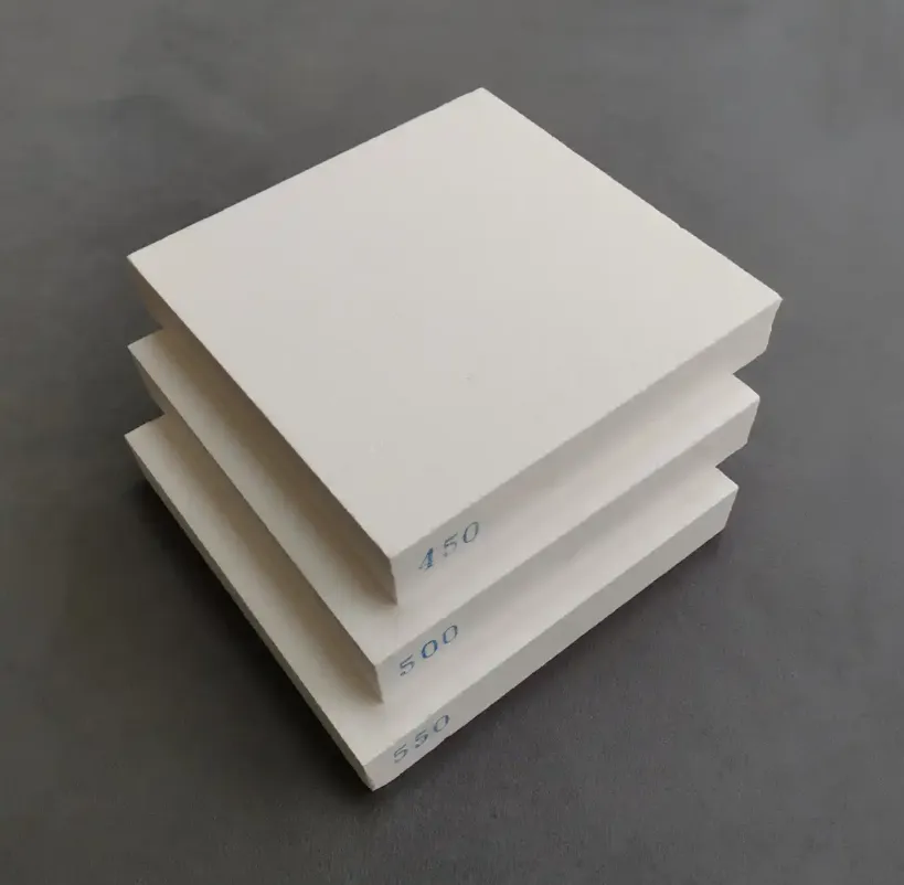
Ceramic fiber insulation sheets are rigid or semi-rigid flat-format refractory insulation products manufactured from high-temperature alumina-silica ceramic fibers consolidated with inorganic binders into precise, dimensionally stable panels used for furnace lining, kiln construction, backup insulation, and high-temperature process equipment thermal barriers. Available in continuous service temperature ratings from 2300°F (1260°C) to 2600°F (1430°C) and above, ceramic fiber insulation sheets outperform blanket products in applications requiring flat, load-bearing surfaces, precise dimensional tolerances, and resistance to gas velocity erosion at the hot face.
If your project requires the use of Ceramic Fiber Insulation Sheet, you can contact us for a free quote.
At AdTech, we supply ceramic fiber insulation sheets to aluminum casthouse operators, steel heat treatment facilities, industrial kiln builders, and OEM furnace manufacturers, ceramic fiber insulation sheets solve the specific problems that blanket and loose fiber products cannot — they provide a self-supporting, machinable, cuttable thermal barrier that maintains its geometry under compression loading and gas flow conditions where flexible blanket would erode, compress unevenly, or fail to maintain dimensional accuracy. If your application requires flat insulation surfaces, tight thickness tolerances, or a rigid thermal barrier that can be cut to complex shapes, ceramic fiber insulation sheets in the 2300°F to 2600°F range are the correct product family to evaluate.
What Is a Ceramic Fiber Insulation Sheet? Composition and Manufacturing
The term “ceramic fiber insulation sheet” is used in the market to describe several related but distinct product formats. Understanding the differences is essential before making a procurement decision.
Product Format Clarification
In commercial practice, “ceramic fiber insulation sheet” refers to products in three main formats:
Rigid ceramic fiber board: A dense, rigid panel manufactured through a wet-forming process similar to papermaking, where ceramic fibers are dispersed in water with inorganic binders, formed into a sheet on a moving screen, pressed to remove water, and then dried and fired to create a rigid, dimensionally stable product. This is the most common format sold as “ceramic fiber sheet” or “ceramic fiber board” in industrial markets.
Vacuum-formed rigid shapes: Ceramic fiber products formed by vacuum-depositing fiber slurry onto shaped molds, producing panels with complex geometries and excellent surface finish. These are used for precision insulation applications in semiconductor processing equipment and aerospace.
Semi-rigid needled sheets: Needle-punched ceramic fiber blanket compressed and set at a defined thickness and density, producing a semi-rigid product with better handling characteristics than standard flexible blanket. Less rigid than wet-formed board but more structured than loose blanket.
For this article, we focus primarily on wet-formed rigid ceramic fiber board/sheet — the product most commonly specified for furnace lining applications in the 2300°F to 2600°F temperature range.
Raw Material Composition
The thermal performance capability of a ceramic fiber insulation sheet is determined primarily by its fiber composition.
Standard 2300°F Grade (1260°C):
Fibers contain 52–56% alumina (Al₂O₃) and 44–48% silica (SiO₂). This elevated alumina content compared to standard-grade ceramic fiber (which typically runs 44–47% Al₂O₃) improves resistance to devitrification — the phase transformation from amorphous glass to crystalline mullite and cristobalite that causes fiber shrinkage and embrittlement at high temperature.
2600°F Grade (1430°C):
Fibers incorporate zirconia (ZrO₂) typically at 14–17% by weight, with alumina at 33–36% and silica at 47–50%. The zirconia addition stabilizes the amorphous fiber structure at temperatures where even high-alumina fibers would undergo unacceptable devitrification. This is the defining characteristic of the 2600°F grade — not simply more alumina, but a fundamentally different fiber chemistry involving a third oxide component.
Binder system: The inorganic binder that holds fibers together in the rigid sheet structure is typically colloidal silica, colloidal alumina, or a combination of both. These sol-based binders provide the green strength needed during manufacturing and, after firing, create ceramic necks between fiber contacts that give the finished sheet its rigidity and compressive strength. Some manufacturers use calcium aluminate cement as the binder, which provides slightly higher compressive strength at the cost of some chemical impurity.
Manufacturing Process for Rigid Ceramic Fiber Board
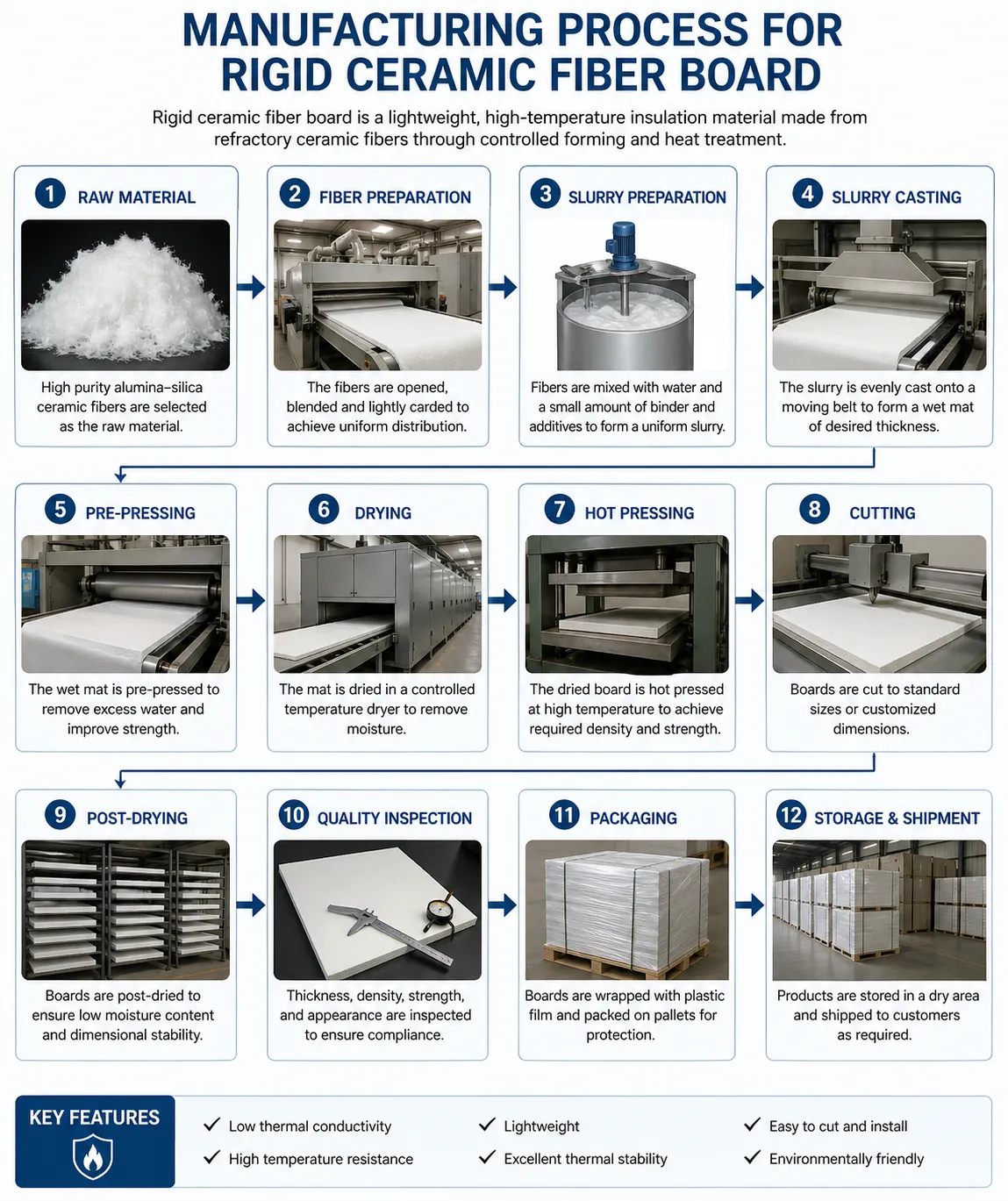
Step 1: Fiber preparation: Bulk ceramic fiber (produced by melt-blowing or spinning) is opened and de-clumped in water to form a uniform fiber suspension at very low concentration (typically less than 1% by weight).
Step 2: Slurry formulation: Colloidal binder, flocculants, and retention aids are added to the fiber suspension to create a stable, well-dispersed slurry.
Step 3: Sheet forming: The slurry is deposited onto a flat forming screen or into a mold. Water drains through the screen under gravity and vacuum, consolidating the fibers into a wet mat of relatively uniform thickness and density.
Step 4: Pressing: The wet mat is mechanically pressed to remove additional water and achieve the target density and thickness. Press pressure directly controls final product density and, consequently, mechanical strength and thermal conductivity.
Step 5: Drying: The pressed mat is dried in heated ovens to remove remaining moisture without thermal damage to the fiber structure. Drying conditions are carefully controlled to prevent surface cracking from rapid moisture gradient.
Step 6: Firing (optional): Some manufacturers fire the dried board at elevated temperature to develop a more complete ceramic bond and to stabilize the product against in-service shrinkage. Fired boards have better dimensional stability but may have slightly higher brittleness.
Step 7: Cutting and finishing: Dried and fired boards are sawn to standard dimensions, surface-ground if required for dimensional precision, and inspected for defects.
2300°F vs. 2600°F Grade: Fiber Chemistry and Temperature Performance
This comparison is the first decision point in any specification process, and the choice has significant cost and performance implications.
What Separates the Two Temperature Grades
The 2300°F and 2600°F grades are not simply different formulations of the same product — they represent meaningfully different material systems with different fiber chemistry, different cost structures, and different performance profiles.
Thermal stability mechanism in 2300°F grade: The elevated alumina content (52–56% Al₂O₃) slows the devitrification process compared to standard-grade fiber. At temperatures up to 1260°C continuous, the fiber remains predominantly amorphous and retains its insulating properties. Above 1260°C, progressive crystallization causes shrinkage at an accelerating rate — which is why the rated temperature is a genuine limit, not a conservative estimate.
Thermal stability mechanism in 2600°F grade: Zirconia (ZrO₂) functions as a crystal structure stabilizer in the fiber matrix. It disrupts the crystallization process and extends the temperature range over which the fiber remains amorphous and dimensionally stable. This is not a marginal improvement — zirconia-containing fibers show dramatically less shrinkage at 1350–1430°C than high-alumina fibers without zirconia.
Performance Comparison at Key Temperatures
| Temperature | 2300°F Grade Behavior | 2600°F Grade Behavior | Practical Implication |
|---|---|---|---|
| 800°C (1472°F) | Fully stable, <0.5% shrinkage | Fully stable, <0.5% shrinkage | Both grades perform identically |
| 1000°C (1832°F) | Stable, <1.0% shrinkage | Stable, <0.5% shrinkage | Minimal difference |
| 1200°C (2192°F) | Stable with adequate margin | Fully stable | 2300°F grade has reasonable margin |
| 1260°C (2300°F) | At continuous service limit | Comfortable operating zone | Critical threshold for 2300°F grade |
| 1350°C (2462°F) | Approaching failure (excessive shrinkage) | Stable, <1.5% shrinkage | 2300°F grade not acceptable |
| 1430°C (2600°F) | Significant devitrification failure | At continuous service limit | Only 2600°F grade viable |
When to Choose 2300°F Grade
The 2300°F (1260°C) grade is the correct specification when:
- The hot-face temperature will not exceed approximately 1150°C (2100°F) continuously, providing 110°C of safety margin below the rated limit.
- The furnace atmosphere is oxidizing or neutral.
- The application does not involve alkali vapor exposure (which accelerates devitrification at lower temperatures).
- Budget optimization is a priority, as 2300°F grade is substantially less expensive than 2600°F.
When to Choose 2600°F Grade
The 2600°F (1430°C) grade is required when:
- Hot-face temperatures consistently reach or exceed 1200°C (2192°F).
- The atmosphere contains alkali vapors (sodium, potassium) that accelerate fiber degradation.
- Long service intervals between maintenance shutdowns make premature shrinkage-related joint opening unacceptable.
- The application is in the glass, specialty ceramics, or advanced materials industry where these temperature levels are routine.
Cost Difference Between Grades
The 2600°F grade typically costs 40–80% more per unit area than equivalent-dimension 2300°F grade product, reflecting the zirconia raw material cost and the more demanding fiber production process. This premium is fully justified when the operating temperature genuinely requires it, but represents wasted cost in applications where 2300°F grade provides adequate performance.
At AdTech, we consistently find that customers who specify 2600°F grade for applications operating at 900–1100°C have been over-specified by a previous supplier or have copied a specification from a more demanding application without verifying its necessity. Correct grade selection from the outset saves significant material cost over a furnace’s lifetime.
Full Technical Specifications: Properties, Dimensions, and Data Tables
Standard Physical and Mechanical Properties
| Property | 2300°F Grade (1260°C) | 2600°F Grade (1430°C) | Test Standard |
|---|---|---|---|
| Fiber composition | Al₂O₃ 52–56%, SiO₂ 44–48% | Al₂O₃ 33–36%, SiO₂ 47–50%, ZrO₂ 14–17% | XRF |
| Bulk density range | 256–384 kg/m³ (16–24 lb/ft³) | 272–400 kg/m³ (17–25 lb/ft³) | ASTM C-167 |
| Standard density | 320 kg/m³ (20 lb/ft³) | 320 kg/m³ (20 lb/ft³) | ASTM C-167 |
| Modulus of rupture (MOR) | 0.5–1.2 MPa | 0.5–1.0 MPa | ASTM C-133 |
| Compressive strength at 10% deformation | 0.3–0.8 MPa | 0.3–0.7 MPa | ASTM C-133 |
| Thermal conductivity at 400°C | 0.12–0.15 W/m·K | 0.11–0.14 W/m·K | ASTM C-177 |
| Thermal conductivity at 800°C | 0.22–0.28 W/m·K | 0.21–0.26 W/m·K | ASTM C-177 |
| Thermal conductivity at 1000°C | 0.30–0.38 W/m·K | 0.28–0.35 W/m·K | ASTM C-177 |
| Linear shrinkage at rated temp (24 hr) | <2.0% | <1.5% | ISO 10635 |
| Shot content | <10% | <10% | ASTM C-1335 |
| Porosity | 88–92% | 87–91% | Archimedes |
| Specific heat capacity | 1.05 kJ/kg·K at 600°C | 0.98 kJ/kg·K at 600°C | DSC measurement |
| Thermal shock resistance | Good | Good | Repeated cycling test |
| Maximum continuous service temp | 1260°C (2300°F) | 1430°C (2600°F) | Grade classification |
| Color | White | White | Visual |
| Non-combustible | Yes | Yes | ASTM E136 |
Standard Dimensions Available
| Dimension Parameter | Standard Options | Custom Options | Tolerance |
|---|---|---|---|
| Length | 900 mm, 1000 mm, 1200 mm | Up to 1500 mm | ±5 mm |
| Width | 450 mm, 600 mm, 900 mm | Up to 1200 mm | ±5 mm |
| Thickness | 12.5 mm, 25 mm, 38 mm, 50 mm, 75 mm, 100 mm | 6–150 mm | ±2 mm or ±10% |
| Surface finish | Standard (as-formed) | Ground (±1 mm thickness) | Per specification |
Thermal Conductivity by Density Comparison
| Density | At 200°C (W/m·K) | At 500°C (W/m·K) | At 800°C (W/m·K) | At 1000°C (W/m·K) |
|---|---|---|---|---|
| 256 kg/m³ (16 lb/ft³) | 0.10 | 0.17 | 0.27 | 0.36 |
| 320 kg/m³ (20 lb/ft³) | 0.09 | 0.15 | 0.25 | 0.33 |
| 384 kg/m³ (24 lb/ft³) | 0.08 | 0.14 | 0.23 | 0.31 |
| 480 kg/m³ (30 lb/ft³) | 0.08 | 0.13 | 0.22 | 0.29 |
Note: Higher density provides modestly lower thermal conductivity at elevated temperatures through radiation suppression, while significantly improving compressive strength and erosion resistance.
Chemical Resistance Profile
| Chemical Environment | 2300°F Grade Response | 2600°F Grade Response | Notes |
|---|---|---|---|
| Oxidizing atmosphere | Excellent | Excellent | Standard service |
| Neutral atmosphere (N₂, Ar) | Excellent | Excellent | No attack |
| Mildly reducing (H₂ <5%) | Good | Good | Monitor for SiO reduction |
| Strongly reducing (H₂ >25%) | Fair | Good | Zirconia improves stability |
| Alkali vapors (Na, K) | Fair (silica attack) | Good (ZrO₂ buffers) | Critical difference |
| Steam at temperature | Fair | Good | Hydrolysis of silica phase |
| Most mineral acids | Good | Good | HF is exception |
| Hydrofluoric acid | Poor | Poor | Attacks all silica-containing ceramics |
| Phosphoric acid | Fair | Fair | Gradual attack above 800°C |
| Molten aluminum (direct) | Poor | Poor | Not for direct contact |
| Molten glass contact | Not recommended | Not recommended | Use dedicated glass contact refractories |
Ceramic Fiber Sheet vs. Blanket, Board, and Module: When to Use Each
This comparison is where most specification decisions are actually made. Each product format has a specific performance niche, and understanding the boundaries of each prevents both performance failures and unnecessary cost.
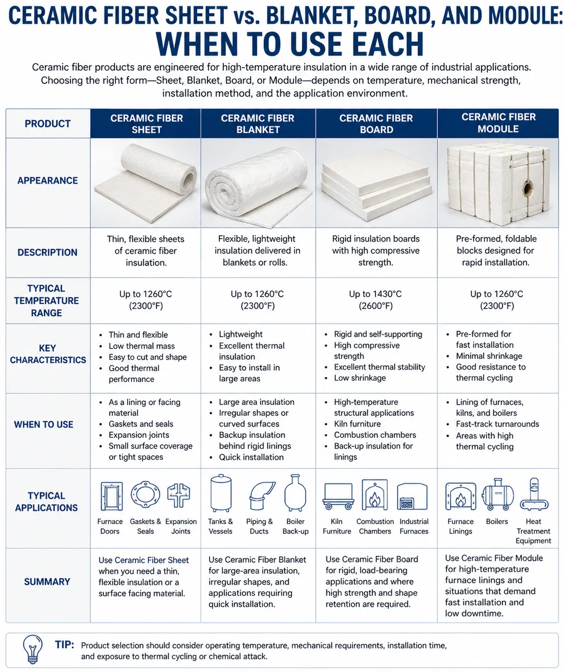
Ceramic Fiber Insulation Sheet vs. Ceramic Fiber Blanket
Both products use essentially the same ceramic fiber as the base material, but they serve fundamentally different engineering functions.
Blanket advantages:
- Lower cost per unit area (typically 30–60% less than rigid board).
- Excellent flexibility for wrapping curved surfaces.
- Better thermal shock resistance due to non-rigid structure.
- Easier installation for simple layered lining systems.
- Module construction provides superior hot-face performance in many furnace applications.
Sheet/board advantages:
- Maintains flat geometry without support — critical for flat hot-face surfaces.
- Resists gas velocity erosion far better than blanket at equivalent density.
- Provides load-bearing capability (shelf supports, kiln furniture, setter plates).
- Machinability allows precision cutting to complex shapes.
- Better surface finish for applications requiring smooth hot-face contact.
- Dimensional stability allows use as a spacer, baffle, or structural element.
The decision rule we apply at AdTech: If the installation surface is flat and the hot face will be exposed to combustion gas velocities above 2–3 m/s, or if the installed material must support any load perpendicular to its face, specify rigid ceramic fiber sheet. In all other flat-surface applications, compare the cost difference against the performance requirements to determine whether blanket or board is the more economical choice.
Ceramic Fiber Sheet vs. Dense Refractory Board (Calcium Silicate, Microporous)
Ceramic fiber sheet (rigid board) competes with other types of rigid insulation boards in applications where the temperature range overlaps.
Calcium silicate board: Rated to approximately 1050°C (1922°F). Lower cost, higher compressive strength, better moisture resistance. Not suitable above 1050°C — the silicate phases dehydrate and lose structural integrity. Below 1050°C, calcium silicate is often the more economical choice.
Microporous insulation board: Achieves thermal conductivity values 40–60% lower than ceramic fiber board at equivalent temperatures. Much thinner insulation profiles for equivalent thermal performance. Very high cost. Used where installation space is severely constrained and performance justifies the premium.
Dense refractory brick: Used where compressive strength, abrasion resistance, or chemical attack resistance requirements exceed what ceramic fiber board can provide. Ceramic fiber board provides far superior thermal insulation performance (lower conductivity, lower thermal mass) for the same thickness but has much lower compressive strength and abrasion resistance.
Product Format Selection Guide
| Requirement | Best Product Format | Second Choice | Avoid |
|---|---|---|---|
| Curved surface insulation | Ceramic fiber blanket | Semi-rigid sheet | Rigid board |
| Flat hot-face surface, high gas velocity | Rigid ceramic fiber board | Blanket with surface coat | Blanket alone |
| Load-bearing shelf or kiln furniture | Dense refractory board or brick | Thick rigid ceramic fiber board | Blanket |
| Maximum thermal efficiency, limited space | Microporous board | Rigid ceramic fiber board | Blanket |
| Complex machined shapes | Rigid ceramic fiber board | Dense refractory board | Blanket |
| Expansion joint filling | Ceramic fiber rope or blanket | Semi-rigid sheet | Rigid board |
| Backup insulation behind hot-face | Blanket (cost-effective) | Rigid board | Dense brick |
| Gasket or sealing element | Ceramic fiber paper or rope | Thin rigid board | Blanket |
Furnace Lining Applications: Hot Face, Backup Layer, and Module Systems
Hot-Face Lining Applications
When ceramic fiber insulation sheets are used as the hot-face material in a furnace lining system, they directly face the furnace interior, combustion gases, and radiant heat flux. This is the most demanding position in the lining system and places the following requirements on the material:
Erosion resistance: Combustion gases and products of combustion pass over the hot face at velocities that can erode soft fiber surfaces. Rigid ceramic fiber board resists this erosion significantly better than blanket because the fiber-binder matrix is dense and consolidated. For gas velocities above 5 m/s at the hot face, even rigid board may require a protective surface treatment (colloidal silica wash, rigidizing treatment) or may need replacement with denser material.
Dimensional stability: The hot-face surface determines the geometry of the furnace interior. If the hot-face material shrinks, warps, or deforms in service, the furnace interior dimensions change, affecting temperature distribution and potentially the process being run. Rigid ceramic fiber board maintains its dimensions better than blanket, particularly for flat hot-face surfaces.
Joint integrity: In a hot-face system constructed from rigid panels, the joints between panels must be managed to prevent hot gas bypass as the board shrinks slightly during initial service. Joints between panels are typically filled with ceramic fiber rope or compressed ceramic fiber blanket, and panels are installed with slight compression at joints to allow for this initial shrinkage.
Backup Insulation Layer Applications
In most industrial furnace lining systems, the hot-face material (which handles the highest temperatures and chemical exposure) is backed by one or more layers of lower-grade insulation that reduce the temperature gradient to the furnace shell. Ceramic fiber insulation sheet serves this backup role in many installations.
Typical backup layer configuration:
- Hot face: Dense refractory brick or high-density castable (handles chemical attack and abrasion).
- Intermediate layer: Ceramic fiber board (2300°F or 2600°F depending on temperature at that depth).
- Backup layer: Ceramic fiber blanket (lower-grade, matching temperature at that depth).
- Outer shell: Steel casing.
In this configuration, the rigid board’s function is primarily thermal — it provides a defined insulation layer of precise thickness with consistent, predictable thermal conductivity. The rigidity of board compared to blanket also prevents the intermediate layer from settling or shifting over time.
Module System Design
Ceramic fiber module systems — where rigid or compressed-blanket modules are anchored to the furnace shell with stud anchors — represent the state of the art in high-temperature furnace lining for demanding applications. Within module systems, ceramic fiber board is used for:
Module faces: Some module designs use a pre-formed rigid board as the hot face of the module, bonded to a compressed blanket core. The board provides superior erosion resistance while the blanket core provides resilience and thermal performance.
Anchor protection boards: Where metal stud anchors penetrate the lining, small ceramic fiber board pieces protect the anchor from radiant heat and extend anchor service life.
Module-to-module gap filling: Rigid board pieces cut to precise dimensions fill gaps between modules to prevent hot gas bypass at module boundaries.
Lining System Design Data
| Furnace Type | Operating Temp | Hot-Face Material | Board Grade | Board Thickness | Backup |
|---|---|---|---|---|---|
| Aluminum holding furnace | 700–850°C | High-density CFS board | 2300°F | 25–50 mm | Blanket 50–100 mm |
| Steel reheat furnace | 1100–1280°C | Dense castable or brick | 2300°F or 2600°F | 50–75 mm | Blanket 100–150 mm |
| Ceramic kiln | 1000–1320°C | CFS board (hot face) | 2600°F | 50–100 mm | Blanket 100 mm |
| Glass annealing lehr | 500–700°C | CFS board | 2300°F | 25–50 mm | Blanket 50 mm |
| Industrial heat treating furnace | 800–1100°C | CFS board (hot face) | 2300°F | 50–75 mm | Blanket 100 mm |
| Semiconductor diffusion furnace | 900–1200°C | High-purity CFS board | 2300°F | 25–50 mm | Low-density blanket |
Industrial Applications Beyond Furnace Lining
Ceramic fiber insulation sheet’s combination of rigidity, machinability, and high-temperature performance extends its use well beyond traditional furnace lining into a broader range of industrial applications.
Kiln Furniture and Setter Applications
In ceramics manufacturing, kiln furniture supports the ware during firing. Ceramic fiber board is used for:
Lightweight setter plates: Traditional dense refractory setter plates store large amounts of heat during each firing cycle, increasing energy consumption and slowing kiln throughput. Ceramic fiber board setter plates have dramatically lower thermal mass, reducing energy use per firing cycle by 20–40% in some operations.
Kiln spacers and separators: Thin ceramic fiber board pieces separate products during firing, preventing sticking while taking up minimal furnace volume.
Bung and plug materials: Kiln bung holes and inspection ports are plugged with ceramic fiber board pieces cut to fit, providing insulation at these penetrations.
Heat Treatment Industry Applications
Heat treating furnaces for metals (annealing, normalizing, carburizing, nitriding, hardening) use ceramic fiber board in multiple roles:
Furnace doors and covers: Furnace door faces lined with ceramic fiber board provide a flat, machinable insulating surface that maintains dimensional stability through repeated thermal cycling. The board can be machined to precise flatness to ensure good contact with door seals.
Radiation shields and baffles: Internal baffles and radiation shields within furnaces, used to manage temperature uniformity, are often fabricated from rigid ceramic fiber board because it can be cut to precise shapes and maintains its geometry at operating temperature.
Muffle and retort linings: Muffle furnaces use ceramic fiber board to line the muffle structure, providing thermal insulation while the muffle material handles the structural function.
Aerospace and Defense Testing Facilities
Ground-based testing facilities for aerospace components — engine test cells, aerodynamic heating test rigs, and high-temperature material testing systems — use ceramic fiber insulation sheet for:
Test section insulation: Insulating panels surrounding test articles protect instrumentation and structural components from radiant heat during high-temperature testing.
Thermal protection mockups: Ceramic fiber board is used to fabricate thermal protection system (TPS) mockup configurations during early development phases before expensive ceramic composite TPS materials are committed.
Electronics and Semiconductor Manufacturing
Diffusion furnace tube insulation: Ceramic fiber board in high-purity grades (with verified low halogen and heavy metal content) insulates the outer surface of quartz diffusion furnace tubes, reducing heat loss and improving temperature uniformity along the tube length.
High-temperature test chamber linings: Environmental test chambers that simulate elevated temperature conditions use ceramic fiber board as the primary lining material when temperatures exceed the capability of conventional insulation.
Rapid thermal processing (RTP) equipment: RTP systems for semiconductor wafer processing use ceramic fiber board in specific configurations to control the thermal environment around the process zone.
Automotive Industry Testing and Manufacturing
Paint booth oven linings: High-volume automotive paint curing ovens use ceramic fiber board as the primary hot-face lining material, providing good erosion resistance to the circulating hot air streams and flat surfaces for uniform heat distribution.
Engine test cell insulation: Automotive engine test facilities use ceramic fiber board to insulate the test cell structure, exhaust ducting, and adjacent equipment from radiant and convective heat generated by running engines at full load.
How to Cut, Machine, and Fabricate Ceramic Fiber Insulation Sheets
One of the significant practical advantages of rigid ceramic fiber board over dense refractory brick is its machinability. The material can be shaped using standard woodworking and metalworking tools, allowing complex profiles to be produced on-site without specialist equipment.
Cutting Tools and Methods
Hand tools:
- Sharp utility knife with a heavy blade for straight cuts in thinner board (up to 25 mm).
- Serrated bread knife for cuts in thicker board where a standard knife blade cannot reach through the full thickness.
- Standard carpenter’s hand saw with a fine-tooth blade for general cutting.
- Keyhole saw for curved internal cuts.
Power tools:
- Circular saw with a fine-tooth blade or a carbide-tipped masonry blade for high-volume straight cutting.
- Band saw for curved cuts and complex profile cutting.
- Jigsaw with a fine-tooth blade for internal cutouts and irregular shapes.
- Lathe for turning round shapes (burner blocks, plugs).
- Router for machining grooves, channels, and complex surface profiles.
Industrial cutting equipment:
- Waterjet cutting for high-precision complex shapes with minimal airborne fiber generation.
- CNC router for high-volume precision parts fabrication.
- Wire saw for delicate cuts in high-density board where saw kerf waste must be minimized.
Machining Surface Finishes
Ceramic fiber board can be machined to surface finishes not achievable with blanket products:
- Standard as-cut surface: Suitable for most applications; surface roughness approximately 0.5–2.0 mm Ra.
- Sanded surface: Using 80–120 grit sandpaper on a block, achieves approximately 0.2–0.5 mm Ra.
- Ground surface: Using a surface grinder, achieves flat surfaces to ±0.5 mm thickness tolerance.
Machined surfaces expose cut fiber ends. In applications where fiber shedding from the machined surface is a concern (semiconductor, food contact), apply a rigidizing treatment (colloidal silica solution) to the machined surfaces after fabrication.
Dust and Fiber Control During Machining
Cutting and machining ceramic fiber board generates airborne ceramic fiber. All machining operations require:
- P100 (N100) respirator or powered air-purifying respirator (PAPR) for sustained machining.
- Local exhaust ventilation with HEPA filtration at the cutting point.
- Wet cutting with water mist where possible to suppress fiber generation.
- Eye protection (safety glasses with side shields minimum; goggles for overhead work).
- Long-sleeved garments and light gloves.
Waterjet cutting effectively eliminates airborne fiber during the cutting operation and produces cleaner cut edges than dry mechanical cutting. For high-volume fabrication shops where workers spend extended periods cutting ceramic fiber board, waterjet cutting is strongly preferred from an occupational health standpoint.
Dimensional Tolerances Achievable in Fabrication
| Operation | Achievable Length/Width Tolerance | Thickness Tolerance | Notes |
|---|---|---|---|
| Hand sawing | ±3 mm | N/A | Depends on operator skill |
| Circular saw | ±1.5 mm | N/A | With fence and guide |
| Band saw | ±1 mm | N/A | With fence |
| CNC router | ±0.5 mm | ±0.5 mm | High-precision machining |
| Waterjet cutting | ±0.3 mm | N/A | Highest precision |
| Surface grinding | N/A | ±0.25 mm | Thickness control |
Installation Methods, Anchoring, and System Design
Direct Adhesive Bonding
For backup insulation applications where the board is bonded directly to a steel shell or concrete structure, high-temperature ceramic adhesive (rated above the expected operating temperature at the bond line) is applied to the board face or the mounting surface and the board is pressed firmly into place. Impalement pins at the shell provide additional mechanical retention.
Adhesive application tips:
- Apply adhesive in a continuous bead or in a grid pattern — do not apply in isolated spots that leave large un-bonded areas.
- Press firmly and hold for 30–60 seconds immediately after placing each board section.
- Allow full adhesive cure time before applying mechanical loads or exposing to heat.
Mechanical Anchoring Systems
Impalement pin system: Stainless steel or alloy pins welded to the furnace shell penetrate the board, with speed clips or anchor plates securing the board. Standard pin spacing is 300–450 mm in both directions, reduced to 200–300 mm for ceiling applications where gravity loading is higher.
Stud anchor and washer system: Longer studs with large-diameter washer plates distribute the anchoring force over a larger board area, reducing stress concentration at the anchor point. This system is preferred for higher-density boards (>320 kg/m³) where the board weight is significant.
Through-bolt system: For very thick board assemblies (>100 mm) or high-load applications, through-bolts with external nut plates provide positive mechanical retention without relying on adhesive bond alone.
Joint Design Between Board Panels
The joint between adjacent ceramic fiber board panels is a critical detail that receives insufficient attention in many installations. Poor joint design leads to hot gas bypass, localized overheating of the shell behind the joint, and progressive joint erosion that accelerates lining failure.
Butt joint with sealant: Adjacent panels butt together with ceramic fiber rope or ceramic fiber paper compressed into the joint. The rope/paper provides a compressible seal that accommodates initial board shrinkage without creating a gap.
Tongue and groove joint: Boards machined with matching tongue and groove profiles interlock to prevent direct line-of-sight hot gas bypass through the joint. More expensive to fabricate but eliminates the need for joint sealant in many applications.
Overlapping layer system: Multiple board layers are installed with joints in each layer offset from the joints in adjacent layers by at least half a board width. No joint runs continuously from hot face to cold face. This is the most reliable system for preventing gas bypass and is standard practice in AdTech’s furnace lining designs.
Ceiling and Overhead Installation
Overhead installation of ceramic fiber board requires more robust anchoring than wall applications because gravity acts perpendicular to the board face, creating peel loading rather than shear loading on the anchor system. Design requirements for overhead installations:
- Minimum anchor density: Double the wall installation anchor spacing (150–225 mm grid for standard ceiling applications).
- Use through-bolt systems for board thicker than 50 mm on ceilings.
- Verify that anchor alloy is rated for the temperature it will experience (the anchor tip is at hot-face temperature; the shell attachment point is at cold-face temperature).
- Apply ceramic adhesive in addition to mechanical anchoring for all ceiling applications.
Health, Safety, and Regulatory Compliance
Regulatory Classification of Ceramic Fiber Board
Ceramic fiber insulation sheet manufactured from refractory ceramic fiber (RCF) carries the same regulatory classification as loose ceramic fiber products. The International Agency for Research on Cancer (IARC) classifies RCF as a Group 2B carcinogen — “possibly carcinogenic to humans” — based on animal inhalation study results. In the European Union, RCF is classified as a Category 1B carcinogen under CLP Regulation (EC) No 1272/2008.
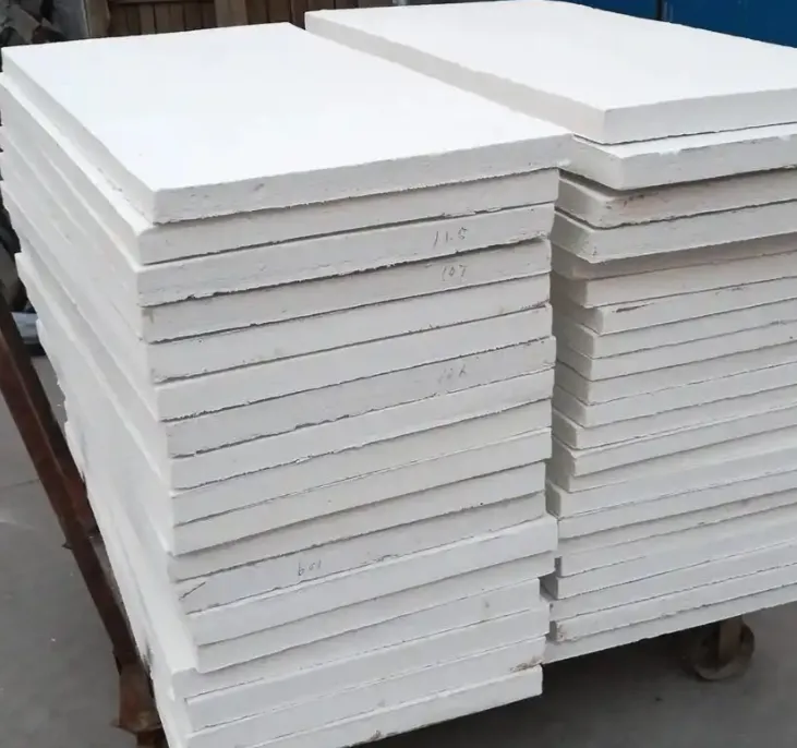
An important practical distinction: rigid ceramic fiber board, in its intact state, generates far less airborne fiber than loose blanket or bulk fiber during normal handling. The fiber-binder matrix holds fibers in place and significantly reduces airborne fiber generation during handling of undamaged, unsawn board sections. The critical exposure events are cutting, machining, grinding, and installation operations that break the board surface and release fibers.
Occupational Exposure Limits
| Country | Regulatory Body | RCF Fiber OEL | Action Level |
|---|---|---|---|
| USA | OSHA | 1 f/cc (8-hr TWA) | 0.5 f/cc |
| EU | EU OSH Framework Directive | 1 f/cm³ | 0.3 f/cm³ |
| UK | HSE (EH40) | 1 f/ml | 0.5 f/ml |
| Germany | TRGS 905 | 1 f/cm³ | Regulatory |
| Australia | Safe Work Australia | 1 f/mL | 0.5 f/mL |
| Japan | Ministry of Health, Labour | 1 f/cm³ | — |
Bio-Soluble Alternatives
For applications with maximum service temperatures below approximately 900–1000°C, alkaline earth silicate (AES) fiber boards are available. These bio-soluble alternatives achieve dissolution rates in simulated lung fluid that qualify for exemption from EU RCF carcinogen classification under Directive 97/69/EC. When bio-solubility is a procurement requirement and the application temperature permits, AES fiber boards are the appropriate specification.
For 2300°F and 2600°F applications, no commercially available bio-soluble fiber maintains adequate thermal performance — these grades genuinely require RCF fiber chemistry. The regulatory management approach for these high-temperature applications must focus on engineering controls, respiratory protection, and worker exposure monitoring rather than material substitution.
Sourcing, Quality Verification, and Specification Checklist
Key Quality Parameters to Verify
When purchasing ceramic fiber insulation sheet, particularly for furnace lining applications where performance failures have significant economic consequences, the following quality parameters require active verification rather than blind acceptance of supplier data sheets.
Fiber composition verification: Request XRF analysis confirming the Al₂O₃, SiO₂, and ZrO₂ (for 2600°F grade) percentages. A product claiming 2300°F rating must show minimum 52% Al₂O₃. A product claiming 2600°F rating must show approximately 14–17% ZrO₂. These are not details that responsible buyers should accept on faith.
Linear shrinkage testing: Request test data showing linear shrinkage after 24 hours at the rated service temperature. Excessive shrinkage (above 2% for 2300°F grade at 1260°C, or above 1.5% for 2600°F grade at 1430°C) indicates either incorrect fiber chemistry or processing problems that will cause premature in-service performance failure.
Modulus of rupture (MOR): Verify that the board’s flexural strength meets the minimum specification. MOR below 0.5 MPa for standard-density board indicates weak bonding that may cause handling damage and in-service cracking.
Density consistency: Measure board density at multiple points (cut samples from different areas of a board and weigh against volume). Density variation above ±10% from the specified value indicates inconsistent pressing during manufacturing and will produce variable performance in service.
Thermal conductivity data: Request actual test data rather than calculated or estimated values. Thermal conductivity significantly above the published specification indicates higher shot content, higher density variation, or fiber chemistry issues.
Complete Specification Checklist for Purchase Orders
| Specification Item | 2300°F Grade Requirement | 2600°F Grade Requirement |
|---|---|---|
| Temperature classification | 2300°F (1260°C) continuous | 2600°F (1430°C) continuous |
| Fiber chemistry (Al₂O₃ min) | 52% minimum | 33% minimum (with ZrO₂) |
| ZrO₂ content | Not applicable | 14–17% |
| Bulk density | Per application (256–384 kg/m³) | Per application (272–400 kg/m³) |
| Linear shrinkage at rated temp | <2.0% (24 hr) | <1.5% (24 hr) |
| MOR (modulus of rupture) | ≥0.5 MPa | ≥0.5 MPa |
| Thermal conductivity at 800°C | ≤0.28 W/m·K | ≤0.26 W/m·K |
| Shot content | ≤10% by weight | ≤10% by weight |
| Dimensional tolerances | ±5 mm L/W, ±2 mm thickness | ±5 mm L/W, ±2 mm thickness |
| Surface finish | Specify: as-formed or ground | Specify: as-formed or ground |
| Quality certifications | ISO 9001, batch certificate | ISO 9001, batch certificate |
| Chemical composition report | XRF per batch | XRF per batch |
| SDS/MSDS | Current GHS-compliant | Current GHS-compliant |
| REACH compliance | EU markets | EU markets |
Supplier Qualification Criteria
Beyond product specifications, supplier capability affects long-term procurement reliability:
- ISO 9001 certified manufacturing facility.
- Demonstrated capability to maintain lot-to-lot consistency (request historical data).
- Technical support team capable of addressing application engineering questions.
- Documented raw material traceability.
- Third-party laboratory test reports from accredited facilities for critical specifications.
- Responsive lead time for standard dimensions and reasonable lead time for custom sizes.
Frequently Asked Questions About Ceramic Fiber Insulation Sheets
1: What is the difference between ceramic fiber insulation sheet and ceramic fiber board?
In practical commercial usage, “ceramic fiber insulation sheet” and “ceramic fiber board” refer to the same product category — rigid flat-format ceramic fiber insulation manufactured through a wet-forming process with inorganic binders. Some manufacturers use “sheet” to describe thinner products (under 25 mm) and “board” for thicker products, but this distinction is not universal. Both terms describe rigid, flat ceramic fiber products that can be cut and machined, as opposed to flexible ceramic fiber blanket or loose bulk fiber. When ordering, specify the thickness, density, temperature rating, and dimensions rather than relying on the sheet/board terminology to convey the exact product needed.
2: Can ceramic fiber insulation sheet be used directly as the hot face in a furnace?
Yes, rigid ceramic fiber board is used as a hot-face lining material in many industrial furnace and kiln applications, particularly where the operating temperature is within the board’s rated range and gas velocities are moderate (below approximately 5 m/s). For higher gas velocities, the board surface may erode over time, and either a higher-density board (≥384 kg/m³), a rigidizing surface treatment, or a more erosion-resistant hot-face material should be specified. The board’s flat surface and dimensional stability make it well-suited for hot-face use in flat-walled furnaces and kilns. In cylindrical or complex-geometry furnaces, the board must be cut into segments with appropriate joint management to accommodate the geometry.
3: How does the 2300°F (1260°C) ceramic fiber sheet compare thermally to firebrick?
Ceramic fiber board (2300°F grade, 320 kg/m³) has thermal conductivity approximately 0.22–0.28 W/m·K at 800°C, compared to dense firebrick at approximately 0.8–1.5 W/m·K at the same temperature. This means ceramic fiber board provides 3–5 times better thermal insulation per unit thickness than dense firebrick. Additionally, ceramic fiber board’s bulk density (320 kg/m³) is approximately 15% of firebrick’s density (typically 2000–2200 kg/m³), giving it dramatically lower thermal mass. In intermittent-operation furnaces, this lower thermal mass reduces heat-up energy and time significantly. The trade-off is that firebrick provides far superior compressive strength, abrasion resistance, and load-bearing capability. Ceramic fiber board and firebrick are complementary materials used in different layers of a lining system, not direct substitutes.
4: What is the maximum thickness available for ceramic fiber insulation sheet?
Commercial ceramic fiber board is routinely available in thicknesses up to 100 mm (4 inches) in standard production. Some manufacturers produce boards up to 150 mm (6 inches) thick, though these are typically special-order items with extended lead times. For insulation systems requiring total ceramic fiber thickness greater than 100–150 mm, the standard approach is to install multiple layers of board (with joints offset between layers) rather than specifying a single very thick board. Multiple layers with offset joints also provide better thermal performance because they eliminate through-joint hot gas bypass paths.
5: Is ceramic fiber insulation sheet suitable for outdoor applications?
Ceramic fiber board is not recommended for outdoor applications where it will be repeatedly wetted by rain or exposed to sustained high humidity without protection. The inorganic fiber and binder components are themselves unaffected by water, but repeated wet-dry cycling can progressively degrade the binder bonds, reducing mechanical strength over time. If ceramic fiber board must be used in outdoor locations, protect it with a metal casing (aluminum or stainless steel sheet metal) or an inorganic coating that prevents water ingress while allowing any trapped moisture to escape during heat-up. For applications that are permanently outdoors and unprotected, calcium silicate board may be a more appropriate choice at temperatures below 1050°C because of its superior moisture resistance.
6: How do I calculate how many inches of 2300°F ceramic fiber board I need for a specific furnace application?
Required insulation thickness is calculated using heat transfer principles. The simplified calculation: Required thickness (inches) = (Hot-face temp °F – Cold-face temp °F) × k / Q, where k is thermal conductivity in BTU·in/hr·ft²·°F and Q is the acceptable heat flux in BTU/hr·ft². For practical design, use the manufacturer’s published thermal conductivity values at the mean temperature (average of hot-face and cold-face temperatures). As a working reference, 2 inches (50 mm) of 2300°F grade board (8 lb/ft³ density) will maintain a cold-face temperature of approximately 150–200°F (65–93°C) when the hot face is at 1800°F (982°C) under steady-state conditions. For precise calculations, consult the AdTech engineering team with your specific operating temperatures and acceptable heat loss targets.
7: Can ceramic fiber board be used in contact with molten aluminum?
Standard ceramic fiber board is not recommended for direct contact with molten aluminum. Silica in the fiber reacts with magnesium and other active alloying elements in aluminum melts, and the fiber structure is susceptible to erosion and chemical attack by liquid aluminum. In aluminum casting and smelting applications, ceramic fiber board is used as backup insulation behind a working lining of dense, aluminum-resistant refractory (typically high-purity alumina or silicon carbide-based materials). The board never contacts the metal directly. In launder systems and trough insulation, purpose-designed aluminum contact refractories are used at the metal interface, with ceramic fiber board as the backup layer.
8: What is the correct way to join two pieces of ceramic fiber board at a corner?
Corner joints in ceramic fiber board lining systems require careful design to prevent hot gas bypass and accommodate thermal expansion movement. The preferred approach is a mitered corner joint where each board piece is cut at 45 degrees and the two mitered faces meet at the corner. A strip of ceramic fiber paper or thin blanket is compressed into the joint before the final board piece is installed, providing a compressible sealant that accommodates any gap that develops during thermal cycling. An alternative approach uses overlapping L-shaped board pieces at the corner — one piece extends past the corner to overlap the end of the adjacent piece, covering the joint on the hot face side. Butt joints at corners (where board ends simply meet at 90 degrees) should be avoided because they create a direct line-of-sight pathway for hot gas bypass.
9: How long does ceramic fiber insulation sheet last in furnace service?
Service life depends on operating temperature relative to the rated temperature, thermal cycling frequency, gas velocity at the hot face, and chemical environment. In a typical industrial heat treating furnace operating at 900°C with regular thermal cycling, 2300°F grade ceramic fiber board at the hot face achieves 5–8 years of service before thickness loss from erosion and progressive shrinkage requires replacement. In lower-temperature backup insulation positions (600–800°C), service life of 10–15 years is common. In more aggressive conditions (near the rated temperature limit, high-cycling, alkali vapor exposure), service life may be 2–4 years. Regular thickness measurement during maintenance shutdowns allows remaining service life to be estimated before board failure causes problems. The backup insulation position (lower temperature, no direct gas exposure) consistently provides the longest service life.
10: What quality certifications should come with a shipment of ceramic fiber insulation sheet?
A complete quality documentation package for ceramic fiber insulation sheet for industrial furnace applications should include: ISO 9001 certification for the manufacturing facility; batch-specific certificate of conformance confirming the product meets the purchased specification; XRF chemical composition analysis showing Al₂O₃, SiO₂, ZrO₂ (for 2600°F grade), and key impurities per production batch; linear shrinkage test results at the rated temperature; bulk density measurement per ASTM C-167; modulus of rupture per ASTM C-133; thermal conductivity data per ASTM C-177 at key temperatures; current GHS-compliant Safety Data Sheet; and REACH compliance declaration for EU purchases. For semiconductor and pharmaceutical applications, additionally require halogen content analysis, heavy metal content verification, and organic contamination certification. For aerospace applications, require material traceability to raw fiber lot and complete processing records. AdTech provides full documentation packages with all commercial shipments and extended documentation for regulated applications upon request.
Summary: Selecting the Right Ceramic Fiber Insulation Sheet Grade and Configuration
After supporting hundreds of furnace lining projects at AdTech, our accumulated experience reduces to a few consistently applicable principles for ceramic fiber insulation sheet specification.
Temperature grade selection must be honest. Specify the grade that matches the actual hot-face temperature with adequate margin — not the highest available grade. The performance difference between a correctly specified 2300°F board and an over-specified 2600°F board in a 1000°C furnace is zero. The cost difference is 40–80%.
Density selection affects both thermal performance and mechanical durability. Higher density provides better erosion resistance and slightly lower conductivity at high temperatures through radiation suppression, but adds weight and cost. Match density to the specific service demands — standard density (320 kg/m³) covers most applications; higher density (384 kg/m³ and above) is justified by high gas velocity or mechanical loading requirements.
Joint design is as important as material selection. The most expensive ceramic fiber board installed with inadequate joint design will fail at the joints before the board body fails. Design joints with compressible ceramic fiber sealants, use overlapping layer configurations to eliminate through-joint gas bypass, and verify joint integrity during installation.
The 2300°F to 2600°F temperature range covered by ceramic fiber insulation sheet addresses the majority of high-temperature industrial furnace, kiln, and process equipment insulation requirements. Within this range, the material’s combination of low thermal conductivity, low thermal mass, machinability, and flexible product dimensions makes it the most versatile rigid insulation format available to furnace engineers and refractory contractors.
For application engineering support, sample requests, or project-specific specification development, the AdTech technical team is available to assist qualified industrial buyers and furnace engineering teams.
