The single most effective way to raise aluminum furnace efficiency, lower downtime, and reduce total melting cost is to specify a multi-layer refractory lining system that pairs a corrosion- and non-wetting working layer (high-alumina, magnesia, or spinel-rich monolithics or shaped bricks) with a graded backup and insulation layer, applied and cured to tight tolerance and maintained on a scheduled program. Choosing the correct chemistry, density, porosity, thermal conductivity, and installation method will typically double lining lifetime compared with a mismatched, low-quality lining, and will produce measurable savings in energy, metal loss, and repairs.
1. Background: why refractory matters in aluminum melting and holding
Aluminum furnaces present a unique challenge compared with ferrous melting equipment because molten aluminum, its dross, fluxes, and recycling contaminants attack refractory chemistries differently. Refractory linings separate the steel shell from high temperatures and chemically aggressive phases. The lining determines heat losses, metal wetting and penetration, lining lifetime, repair frequency, and therefore operational cost. Designing with the correct refractory family and application technique is the dominant lever to improve thermal efficiency and reduce unscheduled downtime.
2. Service environment and failure mechanisms
2.1 Thermal and chemical conditions inside aluminum furnaces
Typical operating temperatures for aluminum melting range from roughly 700°C up to 820°C during melting and may be higher locally near burners or when superheating; holding temperatures are lower but may stay above 700°C. Refractory materials in direct contact with molten aluminum face:
-
Wetting and penetration by liquid metal and flux materials.
-
Chemical corrosion by oxides, chlorides, and glassy fluxes present in scrap or dross.
-
Thermal shock from rapid heating or poor temperature control.
-
Mechanical abrasion from charge materials, scrap, and handling tools.
-
Localized overtemperature at burner or tap zones leading to sintering or spalling.
Understanding that the lining sees a combined thermal-mechanical-chemical assault explains why no single property guarantees long life. Tradeoffs are required and must be engineered into the lining system.
2.2 Common failure modes
-
Liquid metal penetration and metal-saturation: metal wets into pores and microcracks, producing internal glassy layers and volume changes.
-
Flux or slag attack: fluxes from cleaning agents or scrap melt into and dissolve matrix phases, preferentially attacking silica- or lime-rich phases.
-
Spalling and thermal-shock cracking: differential expansion between layers causes flakes to drop away.
-
Mechanical abrasion: repeated impact from charge or ladles abrades the surface, exposing new material to corrosion.
3. Key material properties and target specifications
Selecting the right refractory begins with explicit target values for density, open porosity, cold crushing strength, thermal conductivity, thermal expansion, and chemistry. Below are practical target ranges found in industry practice and literature.
3.1 Primary engineering targets (typical specification window)
-
Working temperature rating: > 1750°C (for high-alumina or magnesia grades) so the refractory retains structural strength at melt temperatures.
-
Bulk density: 2.4 to 3.2 g/cm³ depending on product family; higher density usually reduces open porosity and wetting but may increase thermal mass.
-
Open porosity: 8 to 18% for working layers; lower porosity lowers metal penetration risk but may reduce thermal shock resistance.
-
Cold Crushing Strength (CCS): > 50 MPa for bricks; > 30 MPa for castables after proper firing/cure.
-
Thermal conductivity: low in insulation layers (< 0.5 W/m·K at service temperature), moderate in working layers (0.8–5 W/m·K depending on composition). Silicon carbide enriched materials have much higher thermal conductivity and should be used only where rapid heat transfer is beneficial.
-
Coefficient of Thermal Expansion (CTE): matched across layers to reduce stresses during cycling.
-
Non-wettability: surface finish and chemistry that discourage aluminum wetting; carbon-containing coatings or anti-wetting coatings can be added.
3.2 Chemical composition and phase considerations
-
High-alumina (Al₂O₃) phases resist acidic slags and are commonly used in contact zones.
-
Magnesia (MgO) systems resist basic slags and have favorable resistance to molten aluminum when engineered with spinel phases.
-
Spinel (MgAl₂O₄) presence improves thermo-mechanical stability and corrosion resistance in mixed environments.
4. Refractory families: features, operating windows, pros and cons
Below we describe principal classes that are relevant to aluminum furnaces and practical selection rules for each.
4.1 High-alumina shaped bricks
Features: Dense corundum phases, available in 45–90% Al₂O₃ grades; strong mechanical strength and refractoriness. Typical application in working zones of melting furnaces.
Advantages: Good resistance to chemical attack from alumina-rich environments, high strength, and dimensional stability.
Limitations: May require anti-wetting coatings to prevent metal penetration; more expensive than some monolithics.
4.2 Magnesia and magnesia-spinel castables
Features: MgO and spinel formulations designed to resist basic slag and metal. Low-cement or ultralow-cement castables provide better high-temperature strength and less shrinkage.
Advantages: Good resistance to flux and metal penetration in certain recycle streams.
Limitations: Lower thermal shock resistance than some alumina grades; hydration sensitivity during storage and installation must be controlled.
4.3 Alumina-silicate castables (low cement)
Features: Widely used due to availability and balanced properties. Modern low-cement and no-cement formulations reduce calcium aluminate cement phases which can be weak in the presence of fluxes.
Advantages: Cost effective and adaptable; good in upper furnace areas outside direct metal contact.
Limitations: Vulnerable to certain flux chemistries when compared to high-alumina or magnesia spinel systems.
4.4 Silicon carbide containing ramming mass and castables
Features: SiC boosts thermal conductivity and abrasion resistance; used in areas where rapid heat transfer or erosion resistance is needed. High thermal conductivity may increase heat loss if applied incorrectly.
Advantages: Excellent abrasion resistance; useful for tap holes or zones with high mechanical wear.
Limitations: SiC oxidizes in air at high temperature unless protected, and high conductivity can raise energy consumption.
4.5 Carbon or graphite containing refractories and coatings
Features: Carbon phases reduce wetting and resist penetration by molten aluminum; often applied as coatings or in carbon-bonded mixes.
Advantages: Reduce metal infiltration and wetting; good for contact surfaces when oxidation risks are managed.
Limitations: Carbon will oxidize in the presence of oxygen; sealing and protective atmospheres or coatings are necessary.
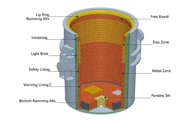
5. Lining architecture and thickness guidelines
A robust lining is multilayered. Each layer performs a different function: working, safety/backup, insulation, and steel shell. Typical configuration and practical thicknesses are shown below.
5.1 Typical multilayer stack (outside → inside)
-
Steel shell — furnace body
-
Insulation layer — low density ceramic fiber or insulating castable, reduces heat loss
-
Backup layer — dense castable or bricks that provide structural support
-
Working layer — high-alumina brick or dense spinel castable in direct contact with metal
5.2 Example thickness guidelines (typical values)
-
Working layer: 25–100 mm in melting zones; heavier in tap and burner areas.
-
Backup layer: 50–150 mm depending on furnace size.
-
Insulation: 25–75 mm of low thermal conductivity material or thicker layers using ceramic fiber modules.
Note: These are starting design values. Actual thickness must consider furnace diameter, burner layout, heat balance, and mechanical handling. A thermal model is recommended during design.
6. Installation, curing, and commissioning protocols
Quality of installation often matters more than product chemistry. The following process steps are commonly used in professional refractory work.
6.1 Pre-installation quality control
-
Verify material certificates: chemical composition, particle size, apparent porosity, binder content, and recommended cure schedule.
-
Ensure substrate and shell geometry are within tolerance.
-
Keep materials dry; monolithic products will react with moisture during transport and storage.
6.2 Installation best practices
-
Use experienced refractory masons and follow manufacturer’s bedding and jointing recommendations.
-
For castables, follow block casting, tamping, or gunning techniques specified by supplier.
-
Gradual heating during curing: staged temperature ramps to drive off free and chemically bound water and to sinter the matrix. Rapid heating invites steam explosions and spalling.
6.3 Anti-wetting surface treatments
-
Apply certified anti-wetting coatings at the working surface when recommended. Coatings reduce metal penetration and extend life; selection must match base refractory chemistry.
7 Inspection, monitoring, and routine maintenance
A proactive inspection program extends lining life and improves safety.
7.1 Inspection schedule
-
Daily visual: look for hot spots, spalling, or scale near burner and tap areas.
-
Weekly: measure shell temperatures at key locations and log trends.
-
Monthly: perform limited borescope inspections of critical zones.
-
Planned shutdown: full internal inspection and thickness measurement.
7.2 Condition indicators
-
Increasing shell temperature at constant operating point
-
New or widening cracks, localized spalling
-
Changes in fuel consumption correlated with shell heat loss
-
Frequent sand or dross ingress
7.3 Repair tactics
-
Cold patching for minor surface defects using ramming mixes.
-
Sectional rebuilding during planned maintenance for deep erosion.
-
Always reapply anti-wetting coatings after repair and re-cure per manufacturer guidance.
8 Lifecycle costing, procurement checklist, and QA testing
8.1 Lifecycle costing principle
Compare total cost per operating day rather than purchase price alone. Consider: material cost, installation hours, furnace downtime, energy loss from poorer insulation, and scrap/metal loss due to contamination. A slightly higher up-front lining cost can generate lower cost per ton melted.
8.2 Procurement checklist (table below)
| Item | Minimum requirement |
|---|---|
| Material certificates | Chemical analysis, refractoriness, bulk density |
| Porosity data | Open porosity and water absorption |
| Mechanical tests | Cold crushing strength, modulus of rupture |
| Thermal properties | Thermal conductivity at service temp, CTE |
| Installation instructions | Curing schedule, mixing water limits, tooling |
| Warranty & service | Supplier guarantee period and site support |
| Anti-wetting option | Recommended coatings and application method |
8.3 QA testing to require from vendor
-
Sample hot face coupons tested for infiltration by molten aluminum (lab infiltration test)
-
Standardized abrasion and corrosion tests (where available)
-
Verification of binder and cement content in low-cement castables
9. Health, safety, and environmental considerations
-
Store monolithics in dry conditions and use appropriate PPE during mixing to avoid respirable dust exposure.
-
Ceramic fibers and insulation materials require respiratory protection and controlled cutting.
-
Dispose of spent refractory material according to local regulations; contaminated refractory with metal residues may be subject to hazardous waste rules in some jurisdictions.
10. Tables: material comparison, thermal windows, and lifecycle example
Table 1. Comparative matrix of common furnace refractories
| Material family | Typical max continuous temp (°C) | Open porosity (%) | Advantages | Limitations |
|---|---|---|---|---|
| High-alumina bricks (60–75% Al₂O₃) | 1750–1850 | 8–15 | Strong, corrosion resistant to alumina-rich slags | May need anti-wetting coating |
| Magnesia-spinel castable | 1700–1850 | 10–18 | Good against basic slags and metal penetration | Lower thermal shock resistance |
| Alumina-silicate low-cement castable | 1600–1750 | 10–20 | Cost effective and versatile | Vulnerable to certain flux chemistries |
| SiC-containing castable/ramming | 1500–1750 | 6–12 | Abrasion resistance, high conductivity | Oxidation risk; may increase heat loss |
| Carbon bonded mixes / coatings | >1600 | 2–8 | Reduce wetting and penetration | Oxidation risk; requires protection |
(Values are practical industry ranges; final selection should use vendor test data).
Table 2: Typical thermal conductivity examples at service temperatures
| Material | Approx. k at 500–800°C (W/m·K) |
|---|---|
| Insulating fiber module | 0.04–0.5 |
| Low-cement alumina castable | 0.8–2.0 |
| High-alumina dense brick | 1.5–3.5 |
| SiC enriched ramming | 5–12 |
(SiC raises conductivity significantly which may not be desirable in energy-sensitive designs).
Table 3. Simple lifecycle cost example (illustrative)
| Scenario | Purchase cost (material + install) | Expected life (months) | Energy penalty per month | Total 24-month cost |
|---|---|---|---|---|
| Low-cost castable | $10k | 6 | $800 | $10k + 4 × $800 = $13.2k |
| Premium spinel/high-alumina | $18k | 24 | $300 | $18k + 24 × $300 = $25.2k |
Interpretation: Even with higher purchase price, longer life and lower energy loss typically lower cost per ton melted. These numbers are simplified example; run site specific energy and downtime models when making decisions.
11. High-Temperature Specifications: Choosing the Right Material
Selecting the exact formulation requires analyzing the specific zone within the melting or holding environment. The requirements differ vastly between the direct impingement zone on a furnace hearth, the upper sidewalls exposed to radiant heat, and the intricate transfer systems like launders.
High-Alumina vs. Silicon Carbide Castables
High-alumina castables dominate the industry due to their excellent balance of mechanical strength and chemical stability. Formulations containing 80% to 85% Al2O3, backed by low cement binder systems, provide exceptional density. High density translates directly to low porosity, leaving no voids available to house penetrating liquid metals.
Conversely, Silicon Carbide (SiC) based refractories offer distinct advantages in specialized zones. SiC possesses exceptional thermal conductivity and extreme resistance to abrasion. These properties make SiC highly desirable in areas requiring rapid heat transfer, such as muffle furnaces or specific radiant tube protections. However, SiC remains susceptible to oxidation at certain temperatures, necessitating specialized glaze coatings to maintain longevity.
Insulation and Thermal Efficiency
Energy costs dominate the financial metrics of aluminum foundries. The refractory lining must contain the liquid metal securely while preventing heat energy from escaping into the surrounding environment. This requirement dictates a multi-layered lining design.
The hot face consists of a dense, heavy castable designed to resist physical wear and chemical attack. Behind this primary defense layer, engineers install insulating refractories. These backing layers utilize lightweight calcium silicate boards, ceramic fiber blankets, or microporous insulation panels. By drastically reducing the thermal conductivity profile from the hot face to the steel shell, the external shell temperature drops below 80°C. This conservation of thermal energy means burners operate less frequently, dropping natural gas consumption significantly.
Table 2: Material Property Comparison Matrix
| Property Metric | High-Alumina (85%) LCC | Silicon Carbide (SiC) Castable | Lightweight Insulating Castable |
| Bulk Density (g/cm³) | 2.85 | 2.65 | 1.10 |
| Cold Crushing Strength (MPa) | 85.0 | 95.0 | 15.0 |
| Porosity (%) | 12% | 15% | 45% |
| Thermal Conductivity (W/m·K) | 2.5 | 15.0 | 0.4 |
| Maximum Service Temp (°C) | 1600 | 1500 | 1200 |
| Primary Application Zone | Hearth, Lower Sidewalls | Tap blocks, Impact pads | Back-up insulation |
12. Application and Installation Procedures
A superior refractory formulation fails rapidly if installed incorrectly. Strict adherence to proper mixing, placing, and curing protocols dictates the final operational success. Manufacturing plants increasingly prefer highly controlled installation methodologies.
Optimal Mixing Ratios and Water Quality
Water acts strictly to initiate the hydration of the calcium aluminate cement. Any excess water beyond the chemical requirement creates voids during the dry-out phase, increasing porosity and destroying mechanical strength. High-performance low cement castables demand an extremely precise water ratio, typically ranging strictly between 4.5% to 5.5% by weight.
Operators must utilize clean, potable water. Impurities, especially chlorides or organic matter, disrupt the crystallization of the cement phases, retarding the setting time and compromising the ultimate strength. Mixers must operate precisely: three minutes of dry mixing to disperse the fine matrix components, followed by exactly four to five minutes of wet mixing. Over-mixing generates excess heat, causing premature setting inside the mixer.
Placement Techniques and Compaction
To ensure maximum density, the installation requires high-frequency vibrators. As the thixotropic castable flows into the mold, the vibration forces trapped air bubbles to rise and escape. Proper vibration liquefies the material temporarily, allowing it to fill complex geometries, particularly around the burner blocks and tap hole assemblies. Care must be taken to prevent over-vibration, which causes aggregate segregation, leaving a weak, cement-rich layer on the surface.
Curing Curves and Baking Schedules
Once placed, the material must cure. Curing requires undisturbed rest at ambient temperatures (ideally 20°C to 25°C) allowing the cementitious bonds to form properly. This phase typically lasts 24 to 48 hours. Covering the exposed surfaces with plastic sheets prevents premature moisture loss.
The baking schedule, or dry-out procedure, represents the most critical phase before introducing molten aluminum. The heating process must carefully evaporate the free water, followed by the chemically combined water, without generating internal steam pressure that could cause explosive spalling.
A standard baking curve involves:
-
Heating at a rate of 15°C per hour until reaching 150°C.
-
Holding at 150°C to allow all free mechanical water to vent completely.
-
Ramping at 20°C per hour to 350°C.
-
Holding at 350°C to release chemically bound water from the cement hydrates.
-
Final ramping at 40°C per hour to the operating temperature, ensuring the establishment of ceramic bonds.
13. Integration with AdTech Equipment
AdTech engineers premium molten aluminum processing equipment. The efficacy of these systems relies heavily on the quality of the internal refractory linings. Degassing units, filtration boxes, and fluid transfer launders experience unique dynamic stresses compared to static holding furnaces.
Refractories in Degassing Units
Inline degassing systems utilize a spinning graphite rotor to inject inert gas (typically argon or nitrogen) into the molten aluminum, removing dissolved hydrogen gas and lifting non-metallic inclusions to the surface. The refractory lining inside the degassing box faces intense fluid turbulence. The high-velocity molten metal constantly scrubs the walls, threatening severe mechanical erosion.
AdTech degassing chambers utilize advanced pre-cast, pre-fired refractory shapes. By casting and firing these components within a highly controlled manufacturing facility, the structural matrix achieves absolute perfection prior to deployment. These pre-cast shapes utilize ultra-low cement formulations heavily fortified with non-wetting agents. The extreme density ensures the turbulent liquid metal cannot erode the wall, preventing any refractory particles from breaking loose and contaminating the highly purified aluminum melt.
Ceramic Foam Filters Support Structures
Ceramic Foam Filters (CFF) physically trap microscopic impurities. The molten aluminum passes through these intricate ceramic networks. The filter bowl, the structure holding the CFF, requires perfect dimensional stability. If the refractory lining warps or cracks, molten metal can bypass the filter entirely, ruining the entire casting run. Castings intended to become aerospace components or ultra-thin foil tolerate absolutely zero inclusions. AdTech designs filter boxes with specialized microporous insulation backed by rigid, non-wetting hot faces, ensuring perfect sealing around the filter media and maintaining a constant temperature to prevent premature freezing of the metal.
Launder Systems and Thermal Retention
Launder networks transport liquid aluminum from the melting furnace, through the degassing and filtration units, directly to the casting station. Heat loss during this journey poses a severe threat. Dropping temperatures require operators to overheat the metal in the primary furnace, wasting massive amounts of energy and increasing gas porosity in the melt.
AdTech launder segments utilize highly engineered composite linings. The hot face features a thin, exceptionally strong non-wetting castable layer. Immediately behind this layer sits highly advanced aerogel or microporous board insulation. This specific configuration ensures the temperature drop across the entire launder network remains negligible, ensuring flawless casting conditions at the terminal end.
14. Troubleshooting Matrix and Solutions
Despite implementing advanced materials, harsh operational conditions eventually cause wear. Addressing anomalies quickly prevents localized damage from escalating into catastrophic equipment failure. Diagnosing the root cause dictates the correct repair strategy.
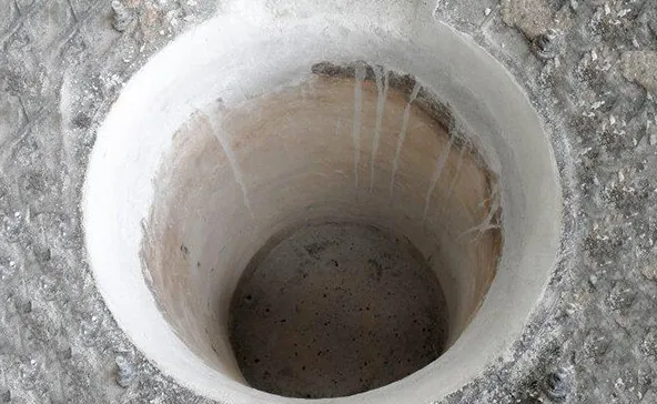
Diagnosing Refractory Cracking and Spalling
Cracks manifest in various forms, each indicating a different failure mechanism. Hairline surface cracks generally result from normal thermal expansion and contraction; they rarely threaten structural integrity. However, deep, penetrating cracks running parallel to the hot face indicate thermal spalling. This phenomenon occurs when temperature gradients exceed the tensile strength of the material, often caused by heating the furnace too rapidly during the initial dry-out phase or exposing the hot face to sudden drafts of cold air.
Structural cracks traversing the entire depth of the lining point toward mechanical failure. This damage usually stems from aggressive cleaning practices using heavy steel tools, or severe impacts from forklift charging operations. Identifying the crack morphology allows maintenance teams to adjust operational procedures directly.
Repair Strategies: Patching Worn Linings Effectively
When targeted areas exhibit severe wear, total replacement remains unnecessary and economically inefficient. Localized patching restores functionality rapidly.
To execute a successful patch:
-
Preparation: Operators must rigorously chip away all loose, damaged, and aluminum-infiltrated refractory. The repair zone must expose clean, virgin matrix material. Creating a dovetailed or undercut geometry ensures the new patch locks into place mechanically.
-
Cleaning: Eliminate all dust using compressed air.
-
Application: Apply a specially formulated patching compound. These compounds feature a chemical bonding mechanism, often using phosphate binders, which adhere aggressively to existing cured refractories without requiring extensive heat to set.
-
Curing: Allow the patch to air dry according to the manufacturer’s protocol, followed by a localized heat application using a portable burner to eliminate moisture before returning the unit to service.
Table 3: Troubleshooting Protocols and Diagnostic Actions
| Observed Failure Mode | Probable Root Cause | Immediate Diagnostic Action | Recommended Repair Strategy |
| Severe Corundum buildup | Depleted non-wetting agent, high porosity | Check operating temperatures, inspect for local hot spots | Chip to clean base, apply non-wetting phosphate-bonded patch |
| Surface Spalling (Flaking) | Rapid heating during dry-out, thermal shock | Review baking schedule logs, check door operation | Remove loose flakes, apply a thin protective wash coating |
| Deep Structural Cracking | Mechanical impact during charging or cleaning | Observe charging procedures, inspect handling tools | Total local breakout to steel shell, recast with high-strength LCC |
| Excessive Heat Loss (Hot Shell) | Breakdown of backup insulation, metal penetration | Conduct thermographic imaging on outer shell | Requires shutdown; remove hot face and replace damaged insulation |
| Metal Bypass around CFF | Dimensional warping of filter bowl seating | Measure seating tolerances physically | Resurface seating area with precision moldable compound |
15. Economic Analysis and Procurement Optimization
Sourcing refractory materials based solely on the initial cost per ton guarantees long-term financial losses. The true metric of success is the Total Cost of Ownership (TCO), calculated by evaluating the lifespan of the lining, the energy saved through superior insulation, and the reduction in maintenance downtime.
Lifecycle Costing Strategies
High-purity, non-wetting castables fortified with barium sulfate command a higher initial purchase price compared to conventional fireclay materials. However, conventional materials require frequent replacement. A standard lining might fail entirely within twelve months due to severe corundum infiltration. An engineered AdTech-approved high-alumina lining, properly maintained, routinely operates past thirty-six months.
Procurement managers must calculate the labor costs associated with tear-out and re-installation, the lost production revenue during the multi-day downtime, and the fuel wasted reheating a cold furnace. When analyzing these variables, premium refractories demonstrate a massive Return on Investment (ROI).
Quality Control and Standardized Testing
Evaluating material data sheets requires understanding specific testing protocols. Foundries should demand compliance with strict American Society for Testing and Materials (ASTM) standards.
-
ASTM C20 measures Apparent Porosity and Bulk Density. Lower porosity guarantees better resistance to liquid metal penetration.
-
ASTM C133 tests the Cold Crushing Strength and Modulus of Rupture. High values ensure resistance to mechanical abuse.
-
ASTM C704 assesses Abrasion Resistance, critical to areas experiencing high-velocity fluid flow or mechanical scraping.
By demanding rigorous testing documentation, facilities secure materials perfectly suited to survive the brutal realities of molten aluminum processing.
16. Future Trends in Aluminum Foundry Refractories
The industry continually pushes toward higher efficiency and stricter environmental controls. Advancements in nanotechnology show immense promise in evolving monolithic refractories. Incorporating nano-silica or nano-alumina into the binder matrix creates exceptionally tight pore structures, achieving porosities below 8%. This microscopic density provides an almost impenetrable barrier to liquid aluminum.
Furthermore, self-flowing castables reduce the reliance on external vibratory equipment. These highly engineered mixes flow like water under their own weight, perfectly filling complex geometries around degassing rotors and launder transitions. This innovation ensures perfectly uniform density throughout the entire casting, eliminating human error during the installation process.
AdTech remains actively involved in integrating these advanced ceramic technologies directly into their filtration and degassing portfolios, continually setting higher benchmarks regarding molten metal purity and operational efficiency. By prioritizing cutting-edge metallurgical science, aluminum producers secure a decisive advantage in a highly competitive global market.
17. Frequently Asked Questions
Aluminum Melting Refractories: 10/10 Technical FAQ
1. Which single refractory type is best for aluminum melting?
There is no universal best. High-alumina materials and magnesia-spinel castables are common top performers in working zones. The best choice depends on scrap chemistry, flux usage, and thermal management. Lab infiltration tests and pilot patches reduce risk prior to full replacement.
2. What lining thickness should I specify for a 2-ton induction melting furnace?
3. How important is porosity in working layer selection?
Very important. Lower open porosity reduces metal infiltration risk. Aim for 8–15% in working faces. Extremely low porosity can affect thermal shock tolerance, so balance is necessary.
4. Should I use silicon carbide in my lining?
5. Are anti-wetting coatings worth the cost?
Yes, in many aluminum applications. They reduce metal penetration and extend lining life, especially when the base refractory is not intrinsically non-wetting. Always follow coating vendor instructions and reapply after repairs.
6. What causes sudden refractory failure?
7. How should I verify vendor data?
8. Is a shaped brick lining better than monolithic?
9. How often should I inspect the lining?
Daily visual checks, weekly thermal logging, and borescope inspection monthly are good practice. Schedule major inspections during planned outages.
10. Can refractory improvements reduce energy use?
Yes. Improved insulation, reduced shell temperatures, and lower heat loss from an optimized lining cut fuel and electricity use and improve melt times. Conduct a heat loss audit to quantify savings.
Final engineering checklist (quick)
-
Define scrap and flux chemistry baseline.
-
Select candidate refractory families and request lab infiltration tests.
-
Specify target porosity, density, CCS, thermal conductivity, and CTE matching.
-
Prepare installation and staged cure schedule in vendor contract.
-
Require on-site technical support on first rebuild.
-
Implement monitoring plan: shell thermocouples, visual logs, borescope.
-
Track energy and downtime pre- and post-installation to compute ROI.
References and suggested reading
Key industry and technical references consulted in preparing this summary include technical papers and manufacturer guidance on refractory selection and maintenance in aluminum furnaces; representative sources include practical refractory design PDFs, industry supplier notes on refractory selection, and materials science reviews on corrosion resistance. Examples used during preparation: technical refractory primers and an industry review of refractory corrosion resistance.
