An ADtech launder dam (refractory baffle / overflow wall) placed inside a launder or settling tank increases residence time, promotes flotation of oxides and dross, controls flowrate and prevents slag carry-over into downstream degassing and filtration stages; when sized and installed correctly it is a low-cost, high-impact component that improves melt cleanliness, protects filters, and raises first-pass casting yields.
Purpose and where a launder dam fits in the melt train
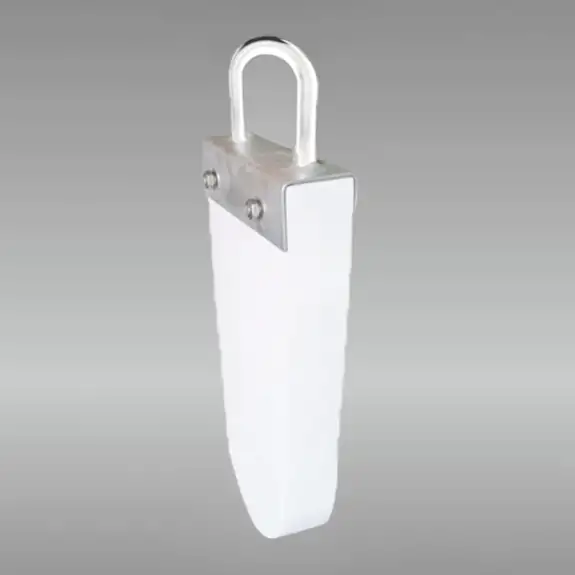
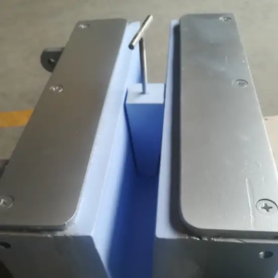
A launder dam is a shaped refractory insert, often a removable block, baffle or weir, fitted inside launders, settling tanks or troughs to:
-
Create a “U” or staged flow path that increases residence time and encourages buoyant impurities to rise to the surface.
-
Prevent direct jet streams and reduce turbulence so that surface oxides are not entrained downstream.
-
Meter discharge through a controlled opening (slot, notch or orifice) so downstream equipment (degasser, filter, pouring spout) receives a steadier flow.
Used correctly, dams reduce re-entrainment of dross and extend the life of downstream ceramic filters and degassers.
Key ADtech design advantages (what makes our launder dam different)
-
High-silicon refractory composition matched to ADtech launders for chemical compatibility and anti-stick performance.
-
Optimized overflow geometry (adjustable slot heights, removable notches) to tune residence time and discharge head loss.
-
Low-profile, quick-change mounting so operators can swap dams during scheduled pauses without cold-line work.
-
Optional boron-nitride or anti-wetting coating for very clean alloy lines to reduce metal adhesion and ease cleaning.
How a launder dam works, fluid dynamics and metallurgy
When molten aluminum enters a settling compartment with a dam, the discharge path is forced through a controlled opening below the melt surface. This creates a mild circulation (a U-turn) that increases time for lighter oxides and dross to float to the surface instead of passing directly into the exit stream. The dam also dissipates kinetic energy of incoming jets and converts chaotic flow into a more laminar pattern. The combined hydrodynamic and buoyancy effects lower inclusion transport to downstream operations and protect filter faces from direct jet impingement.
Typical launder dam styles and when to use them
| Style | Description | Best use |
|---|---|---|
| Fixed weir (solid block) | Simple refractory block with a single overflow crest or notch | Continuous lines with predictable flow rates |
| Adjustable slot weir | Removable plate or slot system that allows raising/lowering the discharge opening | Lines needing flexibility for different pour volumes |
| Flow-spread weir | Wide crest with flow spreader to reduce local velocity | Protects fragile downstream filters from jets |
| Internal baffle array | Series of staggered plates or dams creating multiple settling pockets | High inclusion loads or long residence-time needs |
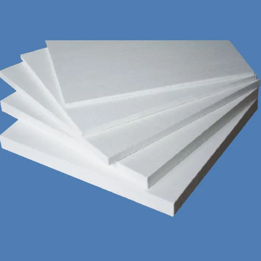
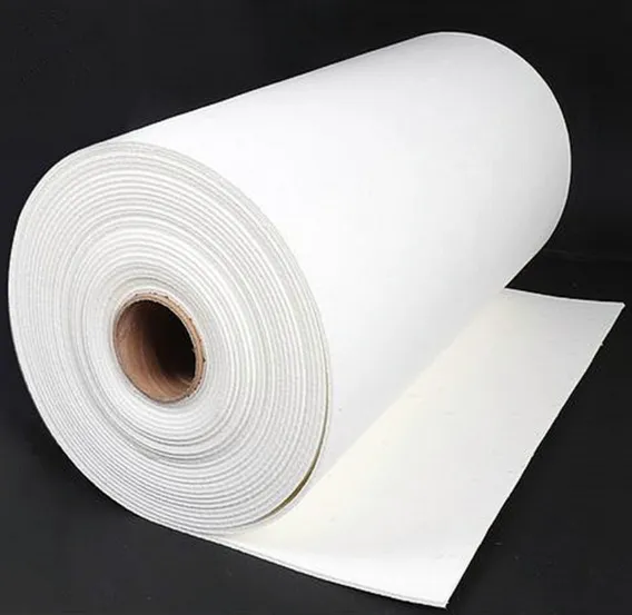
Material selection and refractory considerations
-
High-silicon castables / shaped high-silicon refractories are preferred for aluminum contact because they resist chemical attack and reduce metal sticking.
-
SiC-reinforced or alumina-rich grades can be used where impact/erosion resistance and thermal-shock tolerance are priorities.
-
Coatings (BN, graphite-based anti-wetting layers) are commonly applied on the exposed face to improve slag release and extend service life.
Design note: choose a material system compatible with the launder lining to reduce differential wear at contact points.

Sizing rules of thumb and hydraulic guidance
-
Make the dam crest height and slot geometry such that the downstream discharge velocity is kept low (avoid jet peaking) and the Reynolds number in the launder exits is reduced toward laminar/transitional range when possible. Targeting lower turbulence reduces re-entrainment.
-
Increase residence time by using a taller dam or multi-stage baffles when you need more flotation time for fines and oxides. Typical settling pockets use at least one ladle-to-pour cycle equivalent residence time for effective flotation (site-specific).
-
For adjustable systems, provide a simple calibrated scale so operators can set slot opening for standard batch weights.
Specification:
| Item | Lining | Manual locking dam | Pneumatic or electric dam | Manual lifting dam |
| Standard | Design / As Drawing | Design / As Drawing | Design / As Drawing | Design / As Drawing |
Integration: where to put the dam and how it interacts with upstream/downstream equipment
Recommended sequence for best effect:
-
Furnace/hot-well → 2. Skimming port → 3. Settling pocket with launder dam → 4. Degassing (rotary/vacuum) → 5. Filtration (plate/cartridge/foam) → 6. Pouring.
Place the dam upstream of degassing and filtration so large dross and oxides are removed or concentrated at the surface and can be skimmed before metal hits expensive downstream media. Provide skimming access adjacent to the dam area to remove accumulated slag quickly and safely.
Installation, commissioning and operation checklist
Pre-installation
-
Check compatibility of dam material with launder lining.
-
Confirm physical clearances, lifting points and sealing method.
Commissioning steps
-
Preheat dam and launder area following supplier preheat schedule to avoid thermal shock.
-
Install dam and set the crest/slot to conservative (lower) opening for the first trial.
-
Run instrumented trial pour(s): log pour rate, static head, temperature loss and take RPT/micrograph samples upstream and downstream of the dam area.
-
Adjust dam opening and skimming frequency until you see target improvements in RPT and reduced downstream inclusion counts.
Recommended operator checks
-
Visual check for slag build-up behind the dam.
-
Confirm dam has not shifted and seals are intact.
-
Skim surface scum and record skimming mass.
-
Note pour profile and any signs of localized erosion.
Typical technical specifications
| Parameter | Example value / option |
|---|---|
| Material options | High-silicon castable; SiC-reinforced alumina; coated BN finish |
| Crest types | Fixed, adjustable slot, spreader plate |
| Crest width | 50 mm – 300 mm (custom) |
| Slot adjustment range | 0 – 150 mm (typical) |
| Mounting | Removable clamp / bolt system or mortise seat for shaped bricks |
| Service life | Depends on duty; typical ranges 30–180 days (site dependent) |
| Temperature rating | 700–1200 °C depending on refractory grade |
| Anti-wetting coatings | Boron nitride, BN-graphite or proprietary coatings |
Maintenance, wear monitoring and spare parts
-
Daily/shift: skim and remove surface dross, sweep skimmer ports, visual check for spalling.
-
Weekly: measure any progressive thinning at dam face and record mass of skimmed slag.
-
Monthly: inspect seating surfaces and replace high-wear dams or coating if erosion >10% of original thickness.
-
Spares: keep at least one spare dam of each common slot geometry per critical line plus spare gaskets/clamps.
Tip: track dam life versus tonnage processed to predict replacement cadence and avoid emergency swaps.
Troubleshooting matrix
| Symptom | Likely cause | Corrective action |
|---|---|---|
| Upstream skimming ineffective; slag passes downstream | Slot too large or dam recessed too low | Reduce slot opening; add secondary baffle; increase residence time |
| Rapid dam erosion | High local velocity, abrasive inclusions | Add flow spreader; change to SiC-reinforced dam; check upstream degassing/skimming |
| Metal bypass along edge | Poor seat/gasket or misalignment | Reseat dam; replace gasket; verify clamp torque |
| Thermal spalling or cracking | Inadequate preheat or rapid thermal shock | Preheat slower; ensure oven temperature and ramp meet spec |
| Excessive head loss / slow pours | Overly restrictive slot or clogged openings | Verify slot clearance; clean skimming ports; if needed, increase crest size |
Health, safety and environmental considerations
-
Preheat refractory components and remove moisture before first contact with molten metal to avoid steam explosions.
-
Provide safe skimming procedures and fume extraction near the dam/settling area; dross removal may generate hazardous particulates.
-
Treat spent skimmings as process waste—segregate for metal recovery when possible and comply with local hazardous-waste rules.
-
Use full molten-metal PPE for maintenance or intervention in launder zones.
Economic value and ROI considerations
Value drivers:
-
Lower consumable load on filtration units (longer filter life).
-
Reduced scrap and rework from surface defects and entrained dross.
-
Lower labor and finishing costs due to improved surface quality.
Example ROI snapshot
| Metric | Example |
|---|---|
| Annual throughput | 3,000 t |
| Scrap reduction after dam + skimming | 0.8% absolute (from 2.0% to 1.2%) |
| Annual metal saved | 24 t |
| Metal value (example) | $1,800/t → $43,200 saved per year |
| Incremental cost (dams + maintenance) | Low (site dependent) |
| Typical payback | Often < 12 months for medium/large lines (site-specific) |
Accurate ROI requires local scrap rates, metal pricing and measured filter-life improvements.