An integrated launder and trough system designed with high-silicon refractory linings, robust insulation and proper flow geometry keeps molten aluminum at casting-ready temperature, minimizes turbulence and oxide pickup, and reliably supplies degassing and filtration stations; when engineered and commissioned correctly, a launder system reduces rework, lowers energy loss during transfer and improves process repeatability for medium and large foundries.
Product overview and target application
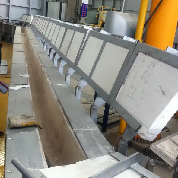
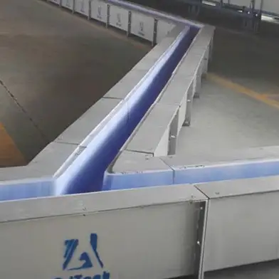
The ADtech integrated aluminum liquid launder system and trough is a modular transfer channel that moves molten aluminum between furnaces, holding vessels, degassers, filtration boxes and pouring stations in aluminum casting operations. The system combines a refractory hot-face (high-silicon or alumina-based), backup insulation, steel support structure and optional covers, gates and instrumentation. It is intended exclusively for aluminum and its alloys in gravity, low-pressure and semi-continuous casting environments where melt cleanliness, temperature control and safe transfer are priorities.
Why launders matter to cast house performance
A well-engineered launder limits heat loss, preserves alloy chemistry and reduces surface oxidation by providing a controlled, low-turbulence channel for metal movement. Short, insulated runs with smooth internal surfaces reduce dross generation and lower the risk of inclusion entrainment before filtration or pouring. Proper launder selection and layout directly influence yield, scrap rates and downstream machining costs.
Key ADtech design features and advantages
-
High-silicon refractory hot-face that resists corrosion and sticky build-up.
-
Low-thermal-loss insulation pack to keep temperature degradation to a minimum and cut energy usage.
-
Smooth internal geometry and tapered transitions to avoid vortices and maintain laminar flow into filtration and degassing equipment.
-
Modular sections and flexible joints permitting quick reconfiguration and repair without full line shutdown.
-
Optional features: heated covers, automatic gates, thermocouples, differential flow monitors and slag skimming ports.
Assembles for Launders:
- Casing
- Lining
- Insulation cover

Materials and construction
Hot-face and backup materials
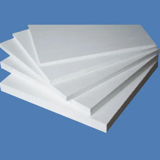
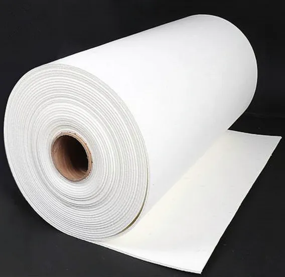
The hot-face is commonly formed from high-silicon castable or shaped alumina-based refractories chosen for chemical compatibility with aluminum, erosion resistance and smooth surface finish. Backup insulation uses low-density refractory fibers or insulating castables to minimize heat flux into the steel shell. The outer shell is fabricated from structural steel sized to carry the insulation, supports and service loads.
Seals and joints
Flexible launder joints and high-temperature gaskets ensure alignment and accommodate thermal expansion while preventing metal bypass. Recommended practice includes provision for removable inspection flanges and clamps to allow routine maintenance and visual checks.
Aluminum Launder Dimensions:
| Item | Length of Lining | Length of Launder | Insulation cover | Special Dimensions |
| Standard | 500-2000mm | 500-2000mm | 200-500mm | As Drawings |
Aluminum Launder Technical parameters:
| Item | Density (g. cm3) |
Rupture modulus (816℃ Mpa) |
>Thermal Expansivity (680℃ K-1) |
Thermal conductivity (540℃W/k.m) |
Operating temperature (MAX) (℃ ) |
| Index | 1.8-2.0 | 18.8-19.8 | 1.56*10-6 | 0.8-0.95 | 1340 |
Thermal performance and temperature management
A compact launder design and well-specified insulation keep metal temperature loss to a minimum. Typical engineered systems limit temperature drop to about 1 to 3 degrees Celsius per meter of transfer under standard conditions, depending on insulation thickness and ambient conditions. Careful routing reduces run length and minimizes heat sinks. Bake-out and preheating procedures are used at installation to drive out moisture and stabilize refractory lining.
Flow engineering: minimizing turbulence and oxide entrainment
Key elements that influence flow quality:
-
Internal profile: smooth radii at bends and gradual transitions reduce vortexing.
-
Slope and gravity head: design the channel slope to sustain required flow rate without jets or splashing.
-
Gates and flow spreaders: controlled gates and spreaders distribute flow into degassing or filter inlets and reduce jet impact on filter faces.
-
Step-down nozzles and calibrated outlets provide predictable pour rates for downstream pouring equipment.
Correct hydraulic design protects filters and degassers from localized high velocity and extends consumable life.
Typical components and optional modules
Table 1: Launder system components
| Component | Purpose |
|---|---|
| Hot-face refractory lining | Melt contact surface; corrosion and erosion resistance |
| Insulation pack | Minimize heat loss and energy consumption |
| Steel shell and support frame | Structural strength and mounting points |
| Movable covers and lids | Reduce heat loss and protect operators |
| Slag skimming ports | Allow removal of surface dross during transfer |
| Gates and flow controllers | Regulate flow to downstream equipment |
| Thermocouples and HMI | Temperature and process monitoring |
| Flexible joints and expansion couplings | Accommodate thermal expansion and maintenance |
Sizing and selection guide
Select launder cross-section, length and slope based on pour mass, pour frequency and required pour height. For short batches a narrow, well-lined trough may be adequate; high-throughput plants often use wider launders with parallel runners or duplex arrangements. When integrating with filtration and degassing equipment maintain adequate benchtop space for inspection and safe access.
Table 2: Typical launder sizing starting points
| Production class | Typical launder width | Typical slope | Notes |
|---|---|---|---|
| Small batch labs | 100–200 mm | 2–5% | Short runs, manual ladling support |
| Medium foundries | 200–400 mm | 3–6% | Inline with degasser and filter boxes |
| High throughput | 400 mm+ or multiple lanes | 4–8% | Parallel launders; automated gates |
Installation, preheating and commissioning
-
Mechanical installation: level steel supports, align joints, torque clamps per drawings.
-
Preheat procedure: uniform controlled heat-up for 1–2 hours to remove moisture and avoid thermal shock to the lining. Typical practice warms the lining slowly until the surface reaches near casting temperatures.
-
Leak and seal check: verify all joints and gaskets before first melt.
-
Instrument calibration: install thermocouples and differential pressure sensors; verify data logging.
-
Trial runs: perform initial pours with sampling, RPT or visual inspections to confirm temperature retention and low oxide pickup.
Integration with melt-treatment train
The launder is the connecting tissue between furnace, degasser, filter and pour station. A recommended sequence is:
-
Furnace or holding vessel
-
Launder transfer with skimming ports and controlled gates
-
Degassing stage (rotary or vacuum) upstream of filters
-
Filtration unit (plate, foam or cartridge) immediately before pouring
-
Final pour into molds or dies
Matching flow geometry to the inlet of degassers and filters prevents re-entrainment and protects expensive filter media.
Safety and regulatory best practices
-
Moisture control: preheat to remove adsorbed water; do not pour onto damp refractory. Normative guidance warns about alloying or dilution above certain temperatures and about safe transfer practices.
-
Fume extraction: local exhaust near skimming and covers to control particulate and flux fumes.
-
Asphyxiant gas caution: if inert gas curtains or purges are used, monitor oxygen and provide alarms.
-
Operator protection: full molten-metal PPE, splash shields and safe access platforms for inspection and maintenance.
-
Waste handling: collect and manage dross and skimmings in compliance with local rules.
Maintenance and inspection program
Table 3: Recommended maintenance schedule
| Interval | Activity |
|---|---|
| Daily | Visual inspection of covers, seals and skimming areas |
| Weekly | Check thermocouples and tighten clamps; clear accessible dross pockets |
| Monthly | Inspect linings for erosion, measure refractory thickness where possible |
| Quarterly | Full joint inspection, flexible coupling check and any minor repairs |
| Annual | Shutdown inspection, refractory repair or relining as needed |
Maintaining a spare modular section and critical gasket inventory reduces production interruptions.
Common problems and corrective actions
Table 4: Troubleshooting matrix
| Symptom | Cause | Action |
|---|---|---|
| Excessive temperature drop | Insulation damage or long unguided run | Inspect insulation, shorten or re-route run, add covers |
| High dross buildup | Turbulence or inadequate skimming | Rework inlet geometry, add flow spreader, implement regular skimming |
| Metal bypass or leaks | Worn gaskets or misaligned joints | Replace seals, realign sections, inspect clamps |
| Refractory spalling | Thermal shock or poor preheat | Review preheat schedule, repair lining, check material grade |
| Unsafe fumes at covers | Inadequate extraction | Add or upgrade local exhaust, review fluxing practice |
Recording events and corrective actions will improve root cause analysis and operation stability.
Economic rationale and ROI considerations
Value drivers for an engineered launder system include reduced scrap, lower energy consumption through better insulation, fewer furnace recharges, and improved downstream filter life. A concise ROI model should include capital cost, reduced metal loss, lower rework, and energy savings.
Table 5: Illustrative ROI snapshot
| Metric | Example |
|---|---|
| Annual throughput | 3,000 tonnes |
| Energy saving from insulation | 3–8% of transfer heat loss (site dependent) |
| Scrap reduction | 0.5–1.5% annual lowering after full integration |
| Annual estimated savings | Varies; metal + energy + labor savings can reach four-figure to six-figure sums depending on plant size |
| Typical payback horizon | 6 to 24 months depending on baseline inefficiencies and metal prices |
A site trial with instrumentation and pre/post metrics yields the most reliable payback forecast.
Selection checklist for purchasing teams
-
Confirm compatible alloy families and maximum operating temperatures.
-
Request thermal performance data showing °C loss per meter under expected conditions.
-
Verify joint and gasket specification for ease of maintenance.
-
Ask for instrument package options and data-logging capability.
-
Insist on a pre-installation site survey and on-site commissioning support.
-
Require documentation on material safety, handling, and recommended preheat cycle.

Molten Aluminum Launder Systems: Technical FAQ
1. What is the main purpose of a launder system?
2. What lining materials are best for aluminum launders?
3. How much temperature is typically lost per meter in a good launder?
4. Do launders require preheating?
5. Can launders be automated?
6. Where should the launder sit in the melt-treatment sequence?
7. What safety systems are recommended?
8. How often should linings be inspected?
9. What causes refractory erosion?
10. What documentation should the vendor supply?
Closing recommendations for implementation
Start with a site survey and thermal model of proposed launder runs. Pilot a short section with instrumentation to quantify temperature retention, head loss and dross formation. Use the pilot data to size insulation, define preheat cycles and set maintenance intervals. This data-driven approach ensures the launder system delivers measurable process and economic gains for your casthouse.