
An ADtech distribution launder provides controlled splitting and metering of molten aluminum into multiple downstream stations while keeping temperature loss minimal, preventing oxide entrainment, and ensuring balanced flow to degassers, filters and pouring points; when engineered with correct refractory lining, manifold geometry and active monitoring, a distribution launder raises casting consistency, lowers scrap and reduces downtime from uneven feeding.
Product overview and primary function
A distribution launder routes molten aluminum from a single feed source into two or more downstream branches. Typical applications include feeding several pouring cells, multiple degassing or filtration units, or parallel die casting machines. The unit balances flow rates, moderates turbulence, and provides local skimming and temperature control so every branch receives metal with equivalent cleanliness and temperature.
Key ADtech advantages and differentiators
-
High-silicon refractory hot-face matched to ADtech launders for long life and low metal adhesion.
-
Engineered manifold geometry that equalizes hydraulic head across branches to avoid starvation or overflow.
-
Integrated flow control modules including adjustable weirs, flow spreaders, and isolation gates for each outlet.
-
Modular sections and quick-change inserts for fast servicing with minimal disturbance to the rest of the line.
-
Optional instrumentation: thermocouples, differential pressure sensors and flow indicators for process logging and traceability.
Curved Launder Specification:
| Item | Length | For casting plate complement | Specification |
| Standard | 200-3000mm | According to the drawings | According to the drawings |
Curved Launder Technical parameters:
| Item | Length | For casting plate complement | Specification |
| Standard | 200-3000mm | According to the drawings | According to the drawings |
Curved Launder Packing:

How a distribution launder improves melt quality and productivity
-
It reduces local jets and eddies by splitting flow gently into multiple outlets, which decreases dross entrainment.
-
It provides dedicated skimming zones and settling pockets near branches so surface oxides are removed before metal leaves the launder.
-
It lets operators tune each branch for different downstream needs, for example one feed to a high-precision cell and another to a heavy-casting line.
-
It lowers thermal and metallurgical variation across parallel stations, improving part uniformity.
Typical configurations and manifold types
Table 1: Common distribution layouts
| Layout type | Description | Best for |
|---|---|---|
| Single-feed, two-branch manifold | One inlet feeding two equally spaced outlets | Small plants with twin pouring stations |
| Single-feed, multiple radial outlets | Inlet with radial branches in a star pattern | Central feed to several short-run cells |
| Tandem launder with isolation gates | Two-stage launder where first stage equalizes, second stage isolates | High-throughput lines requiring selective isolation |
| Duplex banks with bypass line | Parallel launders and a bypass for one branch | Continuous production with hot-swap capability |
Hydraulic design principles
-
Keep transitions smooth with gradual radii at junctions to keep flow laminar.
-
Match branch length and outlet geometry when possible to equalize hydraulic resistance.
-
If branch lengths differ, tune effective resistance using calibrated orifices, adjustable gates or variable-width outlets.
-
Provide a low-velocity settling pocket upstream of the branches to let buoyant contaminants float and be skimmed.
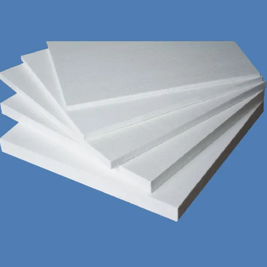
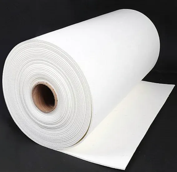
Materials, linings and thermal management
-
Hot-face: high-silicon castable or shaped alumina refractory for chemical compatibility and anti-stick performance.
-
Backup insulation: low-density insulating castables or fiber modules to reduce temperature loss.
-
Steel shell: structural casing with support frame and removable covers for worker safety and easy inspection.
-
Heating options: electric jackets, induction preheat or trace heaters for covers to maintain temperature during low-flow periods.
-
Typical thermal target: keep temperature drop across the launder under 2–4°C per meter under normal ambient conditions.
Flow control hardware and accessories
-
Adjustable weirs and slot plates for coarse balancing.
-
Hydraulic or motorized isolation gates for rapid branch shutoff.
-
Flow spreaders or baffles to moderate jet impact on filter faces.
-
Skimmer ports and removable skimmer baskets.
-
Replaceable wear inserts at branch inlets to reduce erosion.
-
Instrumentation: thermocouples at each branch, differential pressure transducers, and optional flow sensors.
Sizing and selection guideline
Table 2: Sizing quick reference
| Plant scale | Typical inlet mass per pour | Typical branch count | Launder width (mm) |
|---|---|---|---|
| Lab / small cell | < 200 kg | 1–2 | 100–200 |
| Medium foundry | 200–1,000 kg | 2–6 | 200–400 |
| High throughput | > 1,000 kg or continuous | 4–12 or parallel banks | 400+ or multiple lanes |
Selection must include pour cadence, pour height, gating geometry and acceptable head loss. Run computational fluid dynamics or hydraulic mock-ups for complex multi-branch designs.
Installation and commissioning checklist
-
Confirm structural supports and alignment.
-
Preheat launder, inserts and branch covers following supplier ramp schedules to avoid thermal shock.
-
Install instrumentation and verify signals on HMI.
-
Set initial balanced settings: equal slot openings or calibrated orifices for first trial.
-
Conduct instrumented trial pours, collect temperature and flow logs, perform Reduced Pressure Test or inclusion sampling upstream and downstream of branches.
-
Adjust branch resistance and skimming schedule until acceptance criteria are met.
Maintenance and consumables
-
Daily: visual inspection, confirm skimmer baskets and seals, check covers and lifting points.
-
Weekly: check thermocouple calibration, clean accessible slag pockets.
-
Monthly: inspect refractory wear at branch inlets and replace worn inserts.
-
Quarterly: test control actuators on gates and lubricate mechanical parts.
-
Spares to keep on-hand: gaskets, skimmer baskets, wear inserts, thermocouples, heater elements.
Safety and environmental controls
-
Preheat thoroughly; never pour onto damp or cold refractory.
-
Provide local exhaust near skimming areas to capture fumes.
-
Use oxygen or gas monitors if inert curtains or purges are implemented.
-
Ensure safe walkways, guarded covers and proper PPE for operators handling skimming or inspection tasks.
-
Manage collected dross and skimmed material in compliance with local waste and recycling regulations.
Troubleshooting matrix
Table 3: Common problems and corrective steps
| Symptom | Likely cause | Corrective action |
|---|---|---|
| Uneven flow across branches | Mismatched hydraulic resistance | Adjust orifices / gates; re-check branch geometry |
| Excessive dross at one branch | Localized jet impingement or short residence time | Add flow spreader, lengthen settling pocket, increase skimming |
| High temperature loss | Insulation damage or long uninsulated run | Inspect insulation, add covers, verify heater function |
| Seal leakage causing bypass | Worn gaskets or misaligned cover | Replace gaskets, realign clamp plates |
| Rapid erosion at outlet | Abrasive inclusions or high local velocity | Install wear inserts, reduce local velocities, review upstream cleaning |
Integration with degassing, filtration and pour systems
Best practice sequence to maximize metal quality:
-
Furnace / holding vessel
-
Distribution launder with skimming and settling pockets
-
Degassing station(s) placed downstream of initial settling, upstream of final filtration
-
Filtration units at branch outlets or immediately after branch manifold for final polishing
-
Pouring spouts, ladles or die cavities
Tailor placement so each branch receives the correct pre-treatment for its target part family.
Economic justification and ROI considerations
Key benefits:
-
Reduced scrap from more uniform feeding and lower inclusion entrainment.
-
Lower filter consumable rates and longer service life when branches are protected from jets and dross.
-
Reduced rework and higher first-pass yield due to consistent temperature and cleanliness across stations.
Table 4: Example ROI snapshot
| Metric | Example |
|---|---|
| Annual throughput | 3,000 tonnes |
| Scrap reduction from balanced feed | 0.5% absolute |
| Annual metal saved | 15 tonnes |
| Estimated annual savings | Site dependent; metal + machining savings often substantial |
| Incremental capital cost | Moderate relative to full line upgrades |
| Typical payback | 6–18 months depending on baseline variability |
Site-specific trials and accurate scrap metrics produce the best payback estimate.