

Alumina ceramic foam filters (CFF) are the most effective and widely adopted single-use filtration solution for removing non-metallic inclusions from liquid aluminum, and when correctly specified and installed, they consistently reduce inclusion content by 60-90%, measurably improving tensile strength, elongation, fatigue life, and surface finish in the finished casting or rolled product. After working directly with aluminum foundries, continuous casting operations, and rolling mills across multiple continents, we are confident that ceramic foam filtration is not optional for any operation producing aluminum components with structural, pressure-tightness, or surface quality requirements.
AdTech manufactures alumina ceramic foam filters across the full commercial pore size range of 10 PPI to 60 PPI, in standard dimensions from 7 inches to 26 inches, with customised sizes and configurations available for specific launder and filter box designs.
How Does a Ceramic Foam Filter Work? Filtration Mechanisms Explained
The Physics Behind Inclusion Capture in Liquid Aluminum
Understanding filtration mechanics is essential before comparing filter grades or suppliers, because the physical mechanisms determine which filter specification is appropriate for a given inclusion population.
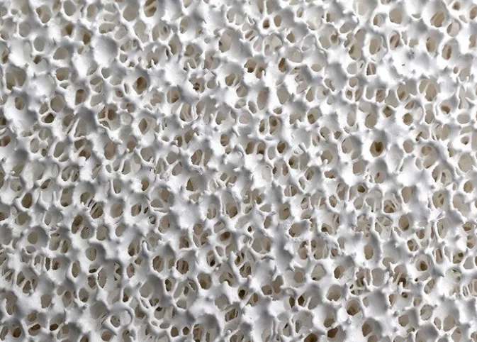
A ceramic foam filter consists of an open-cell three-dimensional network of alumina ceramic strands (called struts or filaments) surrounding interconnected pores. Liquid aluminum flows through this tortuous network under the hydrostatic pressure of the metal head above the filter. The path that metal travels through the filter is far longer than the filter thickness — typically 3 to 5 times longer — because the metal must navigate around struts and through pore throats repeatedly before exiting the filter face.
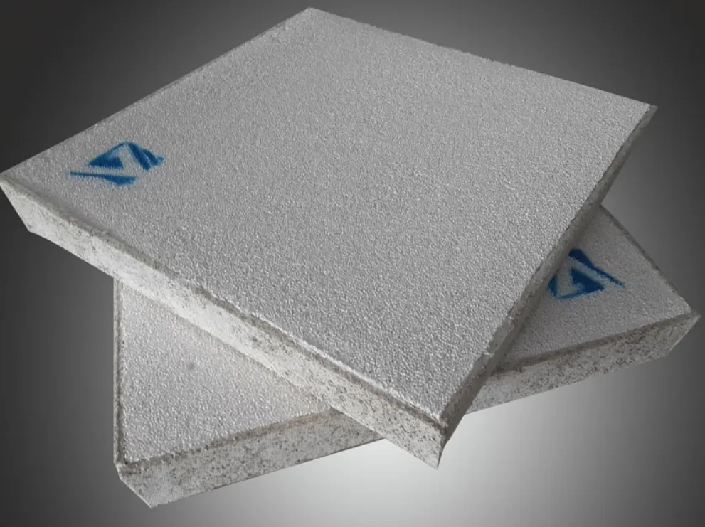
Inclusions in liquid aluminum are captured through three simultaneous mechanisms:
Mechanical interception (sieving): Inclusions larger than the minimum pore throat diameter are physically stopped at pore throats and cannot pass through. This mechanism dominates for coarse inclusions and lower PPI filters.
Inertial impaction: Inclusions with sufficient mass cannot follow the curved streamlines around struts and instead continue in a straight trajectory, impacting the strut surface and adhering to it. This mechanism becomes increasingly effective at higher flow velocities and for denser inclusion particles.
Surface adhesion (cake filtration): The alumina ceramic surface has a natural affinity for aluminum oxide inclusions. When an inclusion contacts a strut surface, electrostatic and chemical bonding forces can retain it even without mechanical trapping. This adhesion mechanism is particularly effective for fine inclusions (below 10 micrometres) that would otherwise pass through mechanical interception.
Over time during a filtration campaign, captured inclusions build up on strut surfaces and at pore throats, progressively narrowing the effective flow passages. This actually improves filtration efficiency during the campaign as the accumulated inclusion layer (the “cake”) acts as an additional filter medium. However, excessive buildup increases flow resistance and can eventually block the filter completely.
Flow Velocity and Its Effect on Filtration Efficiency
Metal flow velocity through the filter has a significant effect on filtration efficiency and inclusion capture rate. The relationship is not linear:
- At very low velocities, residence time is longer and surface adhesion mechanisms have more time to act — but the flow may be insufficient to maintain metal temperature above the liquidus.
- At optimal velocities, all three capture mechanisms operate effectively.
- At excessive velocities, the hydraulic forces on captured inclusions may be sufficient to dislodge previously captured particles, releasing them downstream — a phenomenon called “inclusion re-entrainment” that can cause sudden quality degradation.
Recommended metal velocity through ceramic foam filters:
| Filter Application | Recommended Linear Velocity (cm/s) | Maximum Velocity (cm/s) |
|---|---|---|
| Gravity-fed launder (foundry) | 5 – 15 | 25 |
| Direct chill casting (billet) | 8 – 20 | 30 |
| Continuous casting (strip) | 10 – 25 | 35 |
| Low-pressure die casting | 3 – 10 | 15 |
Alumina vs. Silicon Carbide vs. Zirconia Ceramic Foam Filters: Which Material Is Right?
Comparing the Three Main Ceramic Foam Filter Materials
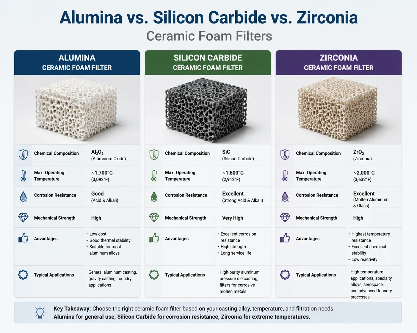
Three ceramic materials dominate commercial aluminum filtration: alumina (Al₂O₃), silicon carbide (SiC), and zirconia (ZrO₂). Each has distinct properties that make it suitable for specific applications and operating conditions.
Alumina Ceramic Foam Filters (Al₂O₃)
Alumina is the standard material for aluminum filtration and accounts for the majority of commercial CFF production globally. Aluminium oxide is chemically inert in liquid aluminum across the full temperature range of aluminum processing (660-900°C), it is mechanically strong enough to withstand the hydraulic pressure of molten metal flow, and its surface chemistry provides good adhesion for aluminum oxide inclusions — the most common inclusion type in aluminum melts.
Key properties of alumina CFF:
- Operating temperature: up to 1,100°C (continuous), 1,200°C (short term).
- Chemical compatibility: excellent with all common aluminum alloys.
- Cost: moderate (lower than zirconia, similar to SiC for equivalent PPI).
- Porosity: 80-90% open porosity (high metal yield).
- Alumina content: typically 60-95% Al₂O₃ (balance SiO₂ and other binders).
- Colour: white to off-white.
Silicon Carbide Ceramic Foam Filters (SiC)
SiC filters offer superior thermal shock resistance compared to alumina and maintain structural integrity through more rapid temperature cycling. They are commonly specified for applications involving intermittent use — where the filter experiences repeated heating and cooling cycles — and for processing at the higher end of aluminum processing temperatures.
SiC filters also conduct heat better than alumina, which helps maintain metal temperature during filtration and can be advantageous in cold weather foundry environments. However, SiC is more expensive than alumina for equivalent pore grades and sizes.
Zirconia Ceramic Foam Filters (ZrO₂)
Zirconia filters are specified primarily for filtering higher-temperature alloys and metals with temperatures above 1,000°C — steel, copper alloys, and special aluminium applications. For standard aluminum foundry use, zirconia offers no meaningful advantage over alumina despite its significantly higher cost.
Material comparison for aluminum filtration:
| Property | Alumina (Al₂O₃) | Silicon Carbide (SiC) | Zirconia (ZrO₂) |
|---|---|---|---|
| Max service temperature (°C) | 1,100 | 1,400 | 1,600 |
| Thermal shock resistance | Good | Excellent | Moderate |
| Chemical stability in Al melt | Excellent | Excellent | Excellent |
| Compressive strength (MPa) | 0.8 – 1.5 | 1.0 – 2.0 | 1.2 – 2.0 |
| Cost relative to alumina | Baseline | 1.2 – 1.8x | 2.5 – 4.0x |
| Colour | White | Black/dark grey | Ivory/cream |
| Best application | Standard Al foundry, DC casting | High thermal cycling, foundry | High-temp metals |
| Standard PPI range | 10 – 60 | 10 – 60 | 10 – 30 |
Our recommendation: For the vast majority of aluminum foundry and casting applications, alumina ceramic foam filters provide the best balance of filtration performance, chemical compatibility, mechanical strength, and cost. Silicon carbide filters are justified when extreme thermal cycling is expected or when the filter box design results in irregular heating patterns.
PPI Rating System: What Do 10, 20, 30, 40, 50, and 60 PPI Mean?
Understanding Pores Per Inch and Its Relationship to Filtration Efficiency
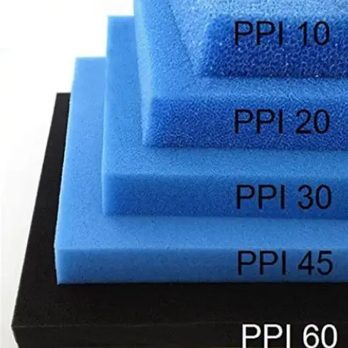
PPI (pores per inch) is the primary specification parameter for ceramic foam filters. It represents the approximate number of complete pore cells per linear inch measured across the filter face. A 10 PPI filter has approximately 10 large pore openings per inch, while a 60 PPI filter has approximately 60 much smaller pore openings per inch.
The relationship between PPI rating and pore size is inverse: higher PPI means smaller pores, finer filtration, and lower flow rate for a given metal head. This creates a direct tradeoff between filtration efficiency (which increases with higher PPI) and flow capacity (which decreases with higher PPI).
Pore characteristics by PPI grade:
| PPI Grade | Average Pore Diameter (mm) | Min. Pore Throat (mm) | Filtration Efficiency | Flow Resistance |
|---|---|---|---|---|
| 10 PPI | 3.0 – 4.0 | 1.5 – 2.5 | Low | Very low |
| 20 PPI | 1.5 – 2.5 | 0.8 – 1.5 | Moderate | Low |
| 30 PPI | 1.0 – 1.5 | 0.5 – 1.0 | Good | Moderate |
| 40 PPI | 0.6 – 1.0 | 0.3 – 0.6 | High | Moderate-high |
| 50 PPI | 0.4 – 0.7 | 0.2 – 0.4 | Very high | High |
| 60 PPI | 0.3 – 0.5 | 0.15 – 0.3 | Excellent | Very high |
It is important to understand that PPI is a nominal rating. Industry-wide standardisation of PPI measurement methodology has historically been inconsistent, which is why purchasing specifications should always include secondary requirements such as pore count range per unit area, minimum/maximum pore diameter, and flow resistance testing at standard conditions.
At AdTech, we verify PPI grade compliance for every production batch using standardised photographic comparison and pore count measurement protocols, and we provide batch certification documentation on request.
Dual-Layer Filtration: Combining PPI Grades
For critical applications where both flow rate and fine filtration are required simultaneously, a dual-layer approach uses two filters in series: a coarser grade (20-30 PPI) upstream to capture large inclusions and protect the downstream filter from premature blockage, and a finer grade (40-60 PPI) downstream to capture smaller inclusions. This approach extends the operational life of the fine filter and maintains acceptable flow rates throughout the casting campaign.
Standard Filter Dimensions and Custom Size Availability
What Standard Sizes Are Available for Alumina Ceramic Foam Filters?
Standard alumina CFF dimensions follow the requirements of the most common filter box designs used in aluminum foundries and continuous casting plants. The dimensions are typically specified in inches (nominal) because filter box tooling has historically been designed in imperial units, though metric equivalents are always available.
Standard square filter dimensions:
| Nominal Size (inches) | Actual Dimension (mm) | Common Thickness (mm) | Typical Application |
|---|---|---|---|
| 7 x 7 | 178 x 178 | 40 / 50 | Small ladles, crucible operations |
| 9 x 9 | 228 x 228 | 40 / 50 | Medium foundry launder |
| 12 x 12 | 305 x 305 | 50 / 60 | Large foundry launder, DC casting |
| 15 x 15 | 381 x 381 | 50 / 60 | Large DC casting operations |
| 17 x 17 | 432 x 432 | 50 / 60 | Industrial continuous casting |
| 20 x 20 | 508 x 508 | 60 / 75 | High-volume rolling slab production |
| 23 x 23 | 584 x 584 | 60 / 75 | Large slab casting |
| 26 x 26 | 660 x 660 | 75 | Very large format casting |
Standard round filter dimensions:
| Diameter (inches) | Actual Diameter (mm) | Thickness (mm) | Application |
|---|---|---|---|
| 7″ round | 178 | 40 | Ladle treatment, small LPDC |
| 9″ round | 228 | 50 | Medium LPDC, sand casting |
| 12″ round | 305 | 50 | Larger LPDC, permanent mould |
| 15″ round | 381 | 50 | Industrial pouring systems |
Custom sizes: AdTech manufactures custom-dimensioned filters to match non-standard filter box geometries. Custom shapes including rectangular, trapezoidal, and specially bevelled edges are available with minimum order quantities applicable. Lead times for custom dimensions are typically 3-6 weeks from drawing approval.
Filter thickness selection:
Thicker filters provide longer filtration path length, which improves efficiency for inertial impaction and surface adhesion mechanisms while also increasing the total inclusion holding capacity before premature blockage. For high-volume DC casting operations handling several tonnes per filter campaign, thicker filters (60-75mm) are standard. For small batch foundry operations, standard 40-50mm thickness is typically sufficient.
Physical and Chemical Properties of Alumina Ceramic Foam Filters
Technical Specifications That Matter for Filter Performance and Reliability
When evaluating alumina CFF from different manufacturers, the following physical and chemical properties determine actual performance in service. Promotional literature frequently omits quantitative specifications — insist on data sheets with verified values.
Physical properties of AdTech alumina ceramic foam filters:
| Property | Value | Test Method |
|---|---|---|
| Al₂O₃ content | 60 – 95% | XRF analysis |
| SiO₂ content | 5 – 35% | XRF analysis |
| Open porosity | 80 – 90% | Archimedes method |
| Bulk density | 0.30 – 0.45 g/cm³ | Geometric measurement |
| Compressive strength | 0.8 – 1.5 MPa | Uniaxial compression |
| Modulus of rupture | 0.6 – 1.2 MPa | 3-point bend test |
| Maximum service temperature | 1,100°C (continuous) | Thermal testing |
| Thermal shock resistance | 5+ cycles (room temp to 800°C) | ASTM C1363 |
| Water absorption (wettability) | > 95% | Capillary absorption |
| Dimensional tolerance | ±2mm (length/width) | Caliper measurement |
| Flatness | < 1.5mm deviation | Surface plate measurement |
Why alumina content matters: Higher alumina content generally corresponds to better chemical stability, higher temperature capability, and better surface affinity for aluminium oxide inclusions. Filters with alumina content below 60% rely more heavily on silica-based binders, which can introduce silica contamination into the melt at elevated temperatures if the filter is improperly preheated or if temperature spikes occur during casting. Our standard production filters maintain alumina content above 70% for routine applications and above 90% for premium aerospace-grade filtration.
Compressive strength and mechanical reliability: A filter that fractures in service causes an immediate and catastrophic quality event — a sudden flood of ceramic particles and previously captured inclusions releases into the downstream melt. Compressive strength specification ensures the filter can withstand the hydrostatic pressure of the metal column above it without fracturing. For filters used in deep filter boxes (metal head above 200mm), always verify that the compressive strength specification covers the maximum expected hydrostatic load.
How to Select the Right PPI Grade for Your Application
A Practical Framework for Ceramic Foam Filter Grade Selection
PPI grade selection is the decision that most significantly affects both filtration quality and operational feasibility. Selecting a grade that is too coarse allows fine inclusions to pass; selecting a grade that is too fine results in premature blockage, insufficient flow rate, and potential metal freezing in the launder.
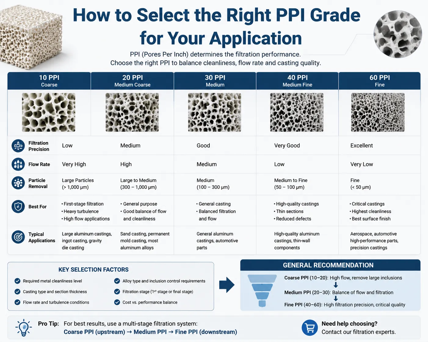
The selection framework considers five factors simultaneously:
Factor 1 — Incoming melt quality: The higher the inclusion content in the incoming melt, the coarser the filter grade needed to prevent rapid blockage. A melt that has been thoroughly degassed and fluxed contains fewer large inclusions, making it feasible to use a finer filter without premature blockage.
Factor 2 — Target melt cleanliness specification: The final hydrogen and inclusion requirements dictate the minimum filter fineness needed. Aerospace specifications requiring PoDFA (Prefil or Porous Disk Filtration Apparatus) values below 0.1 mm²/kg typically require 40-60 PPI filtration. General die casting specifications may be achievable with 20-30 PPI.
Factor 3 — Metal flow rate requirement: Higher throughput operations need lower flow resistance, which favours coarser filter grades unless filter area is increased proportionally.
Factor 4 — Alloy type: High-magnesium alloys (5xxx, 7xxx series) generate oxide films more readily than low-magnesium alloys and may require one PPI grade finer than the baseline recommendation to achieve equivalent cleanliness. High-silicon alloys (4xxx, A413) have lower viscosity and can flow through finer filters more readily.
Factor 5 — Part criticality and quality specification: Safety-critical structural components for aerospace or automotive chassis applications justify the increased cost and flow management complexity of fine filtration. Non-critical sand castings for architectural use may not require filtration at all.
PPI grade selection matrix by application:
| Application | Recommended PPI | Justification |
|---|---|---|
| Aerospace structural castings | 40 – 60 PPI | Strictest inclusion specification, small defects critical |
| Automotive safety components (knuckles, control arms) | 30 – 40 PPI | High fatigue loading, T6 heat treated |
| Automotive wheels (LPDC) | 30 – 40 PPI | Pressure tightness, fatigue life |
| Automotive powertrain (cylinder head, block) | 30 PPI | Moderate cleanliness with high flow rate |
| High-pressure die casting (structural) | 20 – 30 PPI | Good flow rate needed for HPDC feeding speed |
| Standard HPDC (housings, covers) | 20 PPI | Cost-effective cleanliness for non-structural parts |
| DC casting billets (6xxx, 7xxx for aerospace extrusion) | 40 – 50 PPI | Downstream extrusion defect prevention |
| DC casting rolling slab (automotive sheet) | 30 – 40 PPI | Surface quality for rolling |
| General sand castings | 10 – 20 PPI | Large inclusions only, high flow capacity |
| Non-critical permanent mould castings | 20 PPI | Moderate cleanliness, economical |
Filter Box Design and Installation Requirements
What Filter Box Design Parameters Affect Filtration Performance?
The filter box (or filtration unit) that holds the ceramic foam filter in position is as important to filtration performance as the filter itself. A poorly designed filter box that allows metal to bypass the filter, fails to maintain the filter at operating temperature, or creates turbulent flow above or below the filter face will undermine even a correctly specified filter.

Critical filter box design requirements:
Sealing integrity: The filter must seal against the filter box walls without metal bypass channels. Wollastonite fibre gasket seating strips placed on the filter box ledge provide a compressible seal that conforms to the filter edge geometry when the metal head compresses the filter into position. Without adequate sealing, a fraction of the metal flow bypasses the filter completely, reducing effective filtration efficiency.
Preheating provisions: The filter box must be capable of retaining heat during preheat and of maintaining filter temperature above the metal liquidus during the initial priming period. Filter boxes equipped with gas burner access ports or ceramic fibre insulation panels maintain temperature more effectively than bare steel boxes.
Metal entry design: Metal entering the filter box from the upstream launder should be directed downward onto the filter face — not horizontally across it. Horizontal flow creates non-uniform pressure distribution across the filter face, loading one side preferentially and reducing effective filter area. Stepped or baffled launder entry designs distribute flow more evenly.
Filter box sizing: The filter box internal dimensions should match the filter dimensions within the tolerance of the seating gasket. An oversized filter box allows filter movement during operation and creates bypass gaps. An undersized box cracks the filter during installation.
Standard filter box configuration:
| Component | Material | Function |
|---|---|---|
| Box body | Cast iron or refractory-lined steel | Structural support, heat retention |
| Seating ledge | Machined flat to ±0.5mm | Filter support and sealing surface |
| Gasket/seating strip | Wollastonite ceramic fibre | Compressible seal between filter and ledge |
| Preheat burner port | Refractory lined opening | Gas burner insertion for preheat |
| Insulation lining | Ceramic fibre blanket (25mm) | Reduce heat loss from filter box walls |
| Overflow weir | Integrated in box design | Control metal head on filter face |
Preheating Protocols and Operational Best Practices
Why Is Preheating a Ceramic Foam Filter Critical?
Inserting a room-temperature ceramic foam filter into a stream of liquid aluminum at 720-760°C without preheating causes severe thermal shock. The rapid temperature differential generates tensile stresses within the ceramic struts that exceed the modulus of rupture — the filter cracks or shatters, and ceramic fragments contaminate the downstream melt. This is one of the most common and most preventable causes of filter failure in foundry operations.
Beyond structural integrity, a cold filter will freeze aluminum metal in its pores immediately upon contact with the metal stream. This frozen metal blocks flow and either stops the casting process entirely or forces the bypass of the filter under abnormally high metal head pressure.
Standard preheat protocol for alumina ceramic foam filters:
| Step | Action | Duration | Target Temperature |
|---|---|---|---|
| 1 | Position filter in filter box with gasket seated | – | Room temperature |
| 2 | Begin burner heating at low flame | 10 min | 100 – 200°C |
| 3 | Increase flame to medium heat | 10 min | 200 – 500°C |
| 4 | Full flame heating | 10 – 20 min | 700 – 800°C |
| 5 | Maintain at target temperature | Until metal contact | 700 – 800°C |
| 6 | Prime filter with first metal flow | 1 – 3 min | Metal fills pores |
| 7 | Steady-state filtration operation | Campaign duration | Metal temp maintained |
The gradual ramp rate in the early stages is critical — rapid heating from room temperature to above 400°C in less than 10 minutes risks thermal shock even during the preheat phase. We recommend the two-stage approach: slow initial heating to drive off any moisture absorbed by the filter during storage, followed by faster heating to operating temperature.
Additional operational best practices:
- Store unused filters in a dry, covered location to prevent moisture absorption.
- Never reuse a ceramic foam filter from a previous campaign — the pores are partially blocked with captured inclusions and metal, and structural integrity cannot be verified after cooling
- Verify metal temperature is above 700°C before initiating flow through the filter.
- Monitor metal head on the filter throughout the campaign — a rising head level indicates increasing filter resistance and approaching end of service life.
- Do not exceed the maximum recommended metal head (typically 300-400mm) — excessive pressure can fracture the filter or cause inclusion re-entrainment.
Quality Inspection Methods: How to Verify Filter Performance
How Do You Test Whether a Ceramic Foam Filter Is Actually Working?
Filter performance verification is an area where many foundries rely entirely on downstream casting quality assessments — a reactive approach that identifies problems after defective metal has already been cast. We recommend a combination of incoming filter quality inspection and active campaign monitoring:
Incoming filter quality inspection:
| Test | What It Checks | Acceptable Result |
|---|---|---|
| Visual inspection | Cracks, chips, broken edges, surface damage | Zero visible cracks or damage |
| Dimensional check | Length, width, thickness vs. specification | Within ±2mm tolerance |
| PPI verification | Pore count comparison to reference standard | Within stated PPI range |
| Weight measurement | Consistency of ceramic density | Within ±5% of batch average |
| Compressive strength (batch sample) | Structural integrity | Above minimum specification (0.8 MPa) |
| Chemical analysis (batch cert) | Alumina content, impurities | Per material specification |
In-process campaign monitoring:
Metal head measurement above the filter face provides a continuous indirect indicator of filter condition. As inclusions accumulate in the filter pores, flow resistance increases and the metal head required to maintain flow rate rises. Establishing a maximum allowable metal head (typically 150-250mm depending on filter grade and melt volume) and ending the filtration campaign when this threshold is reached prevents both premature blockage and structural filter failure.
Post-campaign assessment:
After each filtration campaign, the used filter can be cross-sectioned and examined to verify that inclusions were actually captured and distributed through the filter depth. This post-mortem analysis is particularly valuable when investigating casting quality problems or qualifying a new filter supplier.
Melt cleanliness measurement methods:
| Method | What It Measures | Sensitivity | Application |
|---|---|---|---|
| PoDFA (Porous Disk Filtration) | Inclusion area per kg (mm²/kg) | Very high | Aerospace, R&D |
| Prefil-Footprinter | Inclusion concentration in melt | High | Production quality control |
| LiMCA (Liquid Metal Cleanliness Analyser) | Inclusion count and size distribution | Very high | Research, premium production |
| Ultrasonic testing | Porosity and inclusions in solidified part | High | Finished casting inspection |
| X-ray / CT scanning | Porosity distribution in casting | High | Structural casting inspection |
| RPT with density | Hydrogen porosity indicator | Moderate | Routine shop floor check |
Inclusion Types Removed by Ceramic Foam Filtration
What Kinds of Non-Metallic Inclusions Does Filtration Target?
Not all inclusions behave the same way in a ceramic foam filter, and understanding the nature of the inclusions in your specific melt helps predict filtration effectiveness and select the appropriate PPI grade.
Aluminium oxide inclusions (Al₂O₃): The most common inclusion type, generated by oxidation of the melt surface and entrainment of surface oxide films during melt transfer, pouring, or turbulent handling. They appear as folded films (bifilms) or discrete particles. Alumina CFF has particularly high affinity for these inclusions due to chemical compatibility between the filter material and the inclusion composition.
Magnesium oxide inclusions (MgO) and spinel (MgAl₂O₄): Common in magnesium-containing alloys (5xxx, 7xxx, some 6xxx). More challenging to filter than pure alumina inclusions because they have different surface chemistry. Finer PPI grades improve capture efficiency.
Silicon carbide particles: Found in melts processed in SiC crucibles or if SiC-containing tool materials are eroded into the melt. Captured effectively by mechanical interception in 20-40 PPI filters.
Titanium boride (TiB₂) clusters: Added intentionally as grain refiner (Al-5Ti-1B master alloy) but can form agglomerates if added incorrectly or if the melt is held too long after addition. Coarse TiB₂ agglomerates are captured by CFF; fine dispersed TiB₂ passes through as intended.
Refractory fragments: Particles eroded from furnace linings, ladle refractories, or launder surfaces. Size distribution varies widely; coarse fragments (above 0.5mm) are captured effectively by any filter grade.
Inclusion capture efficiency by type and PPI grade:
| Inclusion Type | Typical Size Range (μm) | 20 PPI Capture Rate | 30 PPI Capture Rate | 40 PPI Capture Rate |
|---|---|---|---|---|
| Al₂O₃ films (bifilms) | 50 – 5,000 | 60 – 75% | 75 – 85% | 85 – 95% |
| Al₂O₃ particles | 10 – 200 | 50 – 65% | 65 – 80% | 80 – 92% |
| MgO / spinel particles | 10 – 100 | 45 – 60% | 60 – 75% | 75 – 88% |
| SiC particles | 50 – 500 | 65 – 80% | 78 – 88% | 88 – 95% |
| Refractory fragments | 100 – 2,000+ | 80 – 95% | 90 – 98% | 95 – 99% |
| Fine inclusions < 10 μm | 1 – 10 | 20 – 35% | 30 – 45% | 40 – 60% |
Fine inclusions below 10 micrometres are difficult to capture with ceramic foam filtration alone. For applications requiring removal of sub-10 μm inclusions, additional melt treatment (flux treatment, grain refiner timing optimisation) combined with the finest available CFF grades (50-60 PPI) provides the best practical result.
Performance Data: Filtration Efficiency by PPI Grade
Quantified Improvements in Melt Quality from Ceramic Foam Filtration
The following performance data summarises filtration efficiency measurements from our production trials and customer operation audits. All data reflects alumina CFF in correctly designed filter boxes with proper preheating and installation.
Effect of filtration on melt cleanliness (PoDFA measurement, A356 alloy):
| Condition | PoDFA Value (mm²/kg) | Inclusion Reduction vs. Unfiltered |
|---|---|---|
| Unfiltered melt (degassed, fluxed) | 0.45 – 0.80 | Baseline |
| After 20 PPI filtration | 0.18 – 0.32 | 55 – 65% |
| After 30 PPI filtration | 0.10 – 0.18 | 70 – 80% |
| After 40 PPI filtration | 0.05 – 0.10 | 82 – 90% |
| After 50 PPI filtration | 0.03 – 0.07 | 88 – 94% |
| After dual-layer 30+50 PPI | 0.02 – 0.05 | 92 – 97% |
Effect of filtration on mechanical properties (A356-T6 sand castings):
| Condition | Tensile Strength (MPa) | Elongation (%) | Fatigue Life (cycles at 100 MPa) |
|---|---|---|---|
| Unfiltered | 265 | 6.2 | 85,000 |
| 20 PPI filtered | 278 | 7.8 | 140,000 |
| 30 PPI filtered | 289 | 9.1 | 195,000 |
| 40 PPI filtered | 298 | 10.8 | 260,000 |
| 50 PPI filtered | 305 | 11.5 | 310,000 |
The improvement in fatigue life is particularly striking. Inclusions act as stress concentration points where fatigue cracks initiate. Removing a larger fraction of inclusions (particularly bifilms) through finer filtration produces a proportionally large improvement in fatigue performance — much larger than the improvement in static tensile properties alone.
Ceramic Foam Filter Suppliers and Factory Evaluation Criteria
What Should You Look for When Evaluating a CFF Manufacturer?
The ceramic foam filter market includes manufacturers ranging from fully automated, ISO-certified production facilities producing consistent, traceable product to cottage-scale operations with highly variable quality. The performance difference between a well-made and a poorly made filter of nominally identical specification can be dramatic.
Key factory evaluation criteria for ceramic foam filter procurement:
Raw material sourcing and control: The alumina raw material used for filter production must meet consistent purity and particle size specifications. Factories that purchase alumina from multiple unvalidated sources introduce batch-to-batch variation in filter chemistry and performance.
Slurry preparation and coating process: The foam substrate (typically a polyurethane foam precursor) must be coated with a precisely controlled slurry of alumina, binder, and additives. Coating consistency directly affects strut thickness uniformity, which determines both mechanical strength and pore size distribution.
Sintering furnace control: The burnout and sintering cycle that removes the polyurethane substrate and develops the final ceramic bond structure must be executed with precise temperature and atmosphere control. Inadequate sintering produces weak, friable filters. Over-sintering closes pores and increases flow resistance.
Quality inspection and certification: A credible supplier conducts dimensional inspection, visual inspection, and periodic destructive testing (compressive strength, modulus of rupture) on production samples. They should provide batch certificates with chemical and physical data on request.
Certifications and standards: ISO 9001 quality management system certification is a minimum expectation. Additional certifications relevant to automotive supply (IATF 16949) or aerospace (AS9100) indicate a higher level of process control discipline.
AdTech factory capabilities:
| Capability | Specification |
|---|---|
| Production facility | Dedicated CFF manufacturing facility |
| Quality certification | ISO 9001:2015 |
| PPI range produced | 10, 20, 25, 30, 40, 50, 60 PPI |
| Size range | 7″ to 26″ square, custom available |
| Materials produced | Alumina, silicon carbide, zirconia |
| Batch testing | Compressive strength, dimensional, XRF on every lot |
| Documentation | Batch certificates, material test reports |
| Custom capability | Non-standard dimensions, bespoke PPI grades |
| MOQ (standard sizes) | Available in small quantities for trials |
| Lead time (standard) | 2 – 4 weeks |
| Lead time (custom) | 4 – 8 weeks |
Common Problems During Filtration and How to Resolve Them
Troubleshooting Guide for Ceramic Foam Filtration Issues
Problem: Filter fails to prime (metal does not flow through)
Cause: Filter temperature too low, causing immediate freezing of metal in pores; or metal temperature too low; or pores wetted by moisture.
Resolution: Extend preheat time and verify filter temperature reaches 700°C minimum before contact with metal. Verify melt temperature is at least 720°C. If problem persists, increase metal head height temporarily to create additional hydraulic pressure to force initial priming.
Problem: Metal flow suddenly stops partway through campaign
Cause: Filter has reached maximum inclusion holding capacity and is blocked; or a large inclusion slug has bridged across pore throats; or metal temperature has dropped and partially frozen metal is blocking pores.
Resolution: Monitor metal head height throughout campaign and establish a maximum head threshold as an end-of-campaign indicator. Avoid metal temperature drops during casting operations by maintaining launder temperature. If metal head spike is sudden rather than gradual, suspect a slug of dross or flux entering the filter box from upstream.
Problem: Ceramic fragments found in downstream casting
Cause: Filter has fractured during operation due to thermal shock (inadequate preheat), mechanical impact, or excessive hydraulic pressure; or filter has poor mechanical strength (supplier quality issue).
Resolution: Immediately review preheat protocol and verify compliance. Check filter batch for physical defects before installation. Implement incoming quality inspection. Review metal head data to verify operating pressure was within specification.
Problem: Post-filtration melt quality is no better than pre-filtration
Cause: Metal bypass around filter edges (sealing failure); filter PPI grade too coarse for target inclusions; filter primed with dross-contaminated metal that loaded pores immediately; campaign duration too long (filter saturated and re-entraining inclusions).
Resolution: Inspect filter box sealing gasket and replace if compressed below 50% of original thickness. Review PPI grade selection against inclusion population. Improve upstream melt treatment before filtration. Implement campaign duration limits based on metal head monitoring.
FAQs
Q1: What does PPI mean in ceramic foam filters?
PPI stands for Pores Per Inch. It indicates the approximate number of pore cells counted along one linear inch across the filter face. A 10 PPI filter has large, widely spaced pores suitable for removing coarse inclusions with minimal flow resistance. A 60 PPI filter has very fine, densely packed pores that remove smaller inclusions but require more metal head to achieve equivalent flow rates. Higher PPI ratings provide better filtration efficiency at the cost of higher flow resistance.
Q2: Which PPI grade should I use for aluminum alloy filtration?
The correct PPI grade depends on your application requirements. For aerospace and safety-critical automotive castings, 40-60 PPI is standard. For structural automotive castings (wheels, suspension), 30-40 PPI is appropriate. For general die castings and sand castings of non-critical parts, 20-30 PPI is typically sufficient. If you are unsure, share your alloy specification, casting method, and quality requirements with the filter manufacturer — a reputable supplier can provide a specific recommendation backed by application data.
Q3: Can ceramic foam filters be reused?
No. Alumina ceramic foam filters are single-use consumables. After a filtration campaign, the pores are partially or fully blocked with captured inclusions and frozen metal. Structural integrity cannot be verified after thermal cycling from operating temperature to room temperature. Attempting to reuse a ceramic foam filter risks filter fracture in service (releasing captured inclusions and ceramic fragments into the melt), inadequate filtration performance (blocked pores reduce effective area), and possible casting contamination.
Q4: What is the difference between alumina and silicon carbide ceramic foam filters?
Alumina (Al₂O₃) filters are the standard choice for aluminum filtration — chemically inert in aluminum melts, good mechanical strength, natural surface affinity for aluminum oxide inclusions, and moderate cost. Silicon carbide (SiC) filters offer better thermal shock resistance and are preferred when the filter undergoes frequent or rapid temperature cycling. For standard continuous or batch aluminum filtration operations, alumina performs equivalently or better than SiC at lower cost. SiC filters are justified for applications with irregular heating or particularly demanding thermal cycling requirements.
Q5: How do I calculate the correct filter size for my casting operation?
Filter sizing balances two requirements: sufficient flow area to supply metal to the mould at the required rate without excessive metal head, and sufficient filter volume (area × thickness) to hold the expected inclusion load for the entire campaign without premature blockage. A basic calculation: required filter area (cm²) = metal flow rate (cm³/s) / target linear velocity through filter (cm/s). Target velocities are typically 5-20 cm/s depending on filter grade and application. Contact AdTech with your flow rate, campaign duration, and melt quality data for a specific sizing recommendation.
Q6: What causes a ceramic foam filter to crack during use?
Filter cracking in service is almost always caused by thermal shock from insufficient preheating, mechanical impact during installation or metal contact, or excessive hydraulic pressure from an overly high metal head. Less commonly, poor-quality filters with inadequate sintering (weak ceramic bond) may crack at normal operating conditions. The solution for thermal shock cracking is strict adherence to preheating protocols — a minimum 30-minute graduated preheat reaching 700-800°C before metal contact. Always handle filters carefully during installation since edge chips create crack initiation points.
Q7: How long does a ceramic foam filter last during a casting campaign?
Service life depends on the volume of metal filtered, melt cleanliness, filter PPI grade, and filter size. As a rough reference, a 12-inch 30 PPI alumina filter in a standard aluminum foundry operation typically handles 500-1,500 kg of aluminum before flow resistance rises to the maximum allowable level. Larger filters and coarser PPI grades handle more metal per campaign. Cleaner incoming melt (after thorough degassing and fluxing) extends filter life by reducing the inclusion load the filter must capture. Monitoring metal head height is the most reliable way to determine actual end-of-campaign.
Q8: Where is the ceramic foam filter placed in the casting system?
The filter should be positioned as close to the casting point as possible while remaining accessible for filter changes between campaigns. In continuous DC casting, the filter box is typically installed in the distribution launder between the degassing unit and the casting table. In foundry operations, the filter box is positioned in the pouring launder above the mould or in the pouring cup itself for small castings. The filter must be downstream of all degassing and flux treatment operations since these processes introduce turbulence that would damage a filter if placed upstream.
Q9: What is the holding capacity of a ceramic foam filter?
Holding capacity refers to the total mass of inclusions a filter can capture before becoming too blocked to maintain adequate flow. It is not a fixed specification — it depends on filter volume, PPI grade, and inclusion particle size distribution. Finer inclusions pack more densely and fill pores faster per unit mass compared to coarse inclusions. Empirically, alumina CFF holding capacity ranges from 0.1 to 0.5 kg of inclusions per litre of filter volume for typical aluminum foundry applications. Dual-layer filter arrangements increase total holding capacity by distributing the inclusion load across two filter bodies.
Q10: How should ceramic foam filters be stored before use?
Store ceramic foam filters in their original packaging in a dry, covered area at room temperature. Avoid exposure to moisture — absorbed moisture releases as steam when the filter contacts the preheating flame, which can cause internal cracking. Do not stack heavy objects on top of filters. Inspect each filter before use for cracks, chips, or physical damage that may have occurred during shipping or storage. Filters with any visible damage should not be used — the cost of a replacement filter is negligible compared to the cost of a contamination event in a casting campaign.
Conclusion: Selecting and Using Alumina Ceramic Foam Filters Effectively
Alumina ceramic foam filtration represents one of the highest return-on-investment process improvements available to aluminum casting and casting rolling operations. The capital cost is minimal — the filter itself is a consumable priced in the range of a few dollars to a few tens of dollars depending on size and grade. The performance benefit — 60-95% inclusion reduction, meaningful mechanical property improvements, reduced scrap rates, and extended tooling life — is documented and repeatable when the filter is correctly specified, installed, and operated.
The critical success factors are:
- Correct PPI grade selection matched to your application’s cleanliness requirements and flow rate constraints.
- Proper filter box design with reliable sealing and adequate preheating capability.
- Strict preheating protocol compliance to prevent thermal shock cracking.
- Campaign monitoring through metal head measurement to avoid filter saturation.
- Incoming quality inspection to verify that filter specification is being met by the supplier.
Quick reference: AdTech alumina CFF product range summary:
| PPI Grade | Primary Application | Available Sizes | Thickness Options |
|---|---|---|---|
| 10 PPI | Coarse filtration, high flow rate | 7″ to 26″ | 40, 50, 60 mm |
| 20 PPI | General foundry, standard die casting | 7″ to 26″ | 40, 50, 60 mm |
| 30 PPI | Automotive structural, permanent mould | 7″ to 26″ | 50, 60, 75 mm |
| 40 PPI | High-quality structural casting, DC billet | 7″ to 26″ | 50, 60, 75 mm |
| 50 PPI | Aerospace, precision casting | 7″ to 20″ | 50, 60 mm |
| 60 PPI | Ultra-clean applications, R&D | 7″ to 17″ | 50, 60 mm |
AdTech supplies alumina ceramic foam filters, silicon carbide foam filters, filter boxes, launder systems, and complete melt treatment solutions to aluminum producers worldwide. Our engineering team supports filter selection, filter box design review, and operational troubleshooting. Contact us with your specific application parameters for a targeted product recommendation.