A ceramic foam filter is a three-dimensional, open-cell refractory block used to remove nonmetallic inclusions and control metal flow during mold filling. When placed in a gating system, these filters trap oxide skins, dross, sand and other particles while smoothing flow, so final castings show fewer defects, improved mechanical integrity, and higher surface finish.
What is ceramic foam filter?
A ceramic foam filter is a rigid open-cell ceramic block created from a polymer template that is coated, dried and sintered. The template gives the final part a network of interconnected voids. Molten metal passes through the network while particles become trapped within the internal struts and on pore windows. This filtering occurs through a combination of inertial capture, interception, and deep-bed adsorption across the filter thickness.
Why foundries use ceramic foam filters
Short answer: they improve casting quality, reduce rework, and increase yield.
Longer explanation in bullet form:
-
Remove suspended oxides, slag, sand and other debris that cause surface and internal defects.
-
Produce steadier metal flow that lowers turbulence inside the mold, reducing gas entrapment and cold shuts.
-
Provide thermal resistance that tolerates common melt temperatures for aluminum, iron and steel grades.
-
Offer repeatable performance with standard PPI ratings for filter selection.
Also read: How to Make a Ceramic Filter.
How ceramic foam filtration works
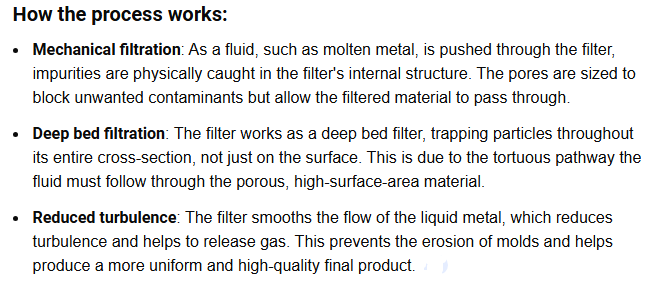
Flow profile and depth filtration
Molten metal travels through many tortuous channels. Particles move toward capture sites on the ceramic struts. Over the filter depth, particle size distributions change. Smaller particles may lodge within the strut matrix. Larger pieces block pore windows near the filter face.
This process is typically called deep-bed filtration in the literature. Capture efficiency depends on pore geometry, pore throat size, melt viscosity, and flow velocity.
Dominant capture mechanisms
-
Inertial impaction: heavier particles fail to follow streamlines, colliding with strut surfaces.
-
Interception: particles following streamlines touch a strut because particle diameter exceeds local gap.
-
Diffusion and adsorption: very fine particles move randomly and adhere to internal surfaces inside the struts.
Flow control benefits
Filters also condition the metal stream. Flow smoothing reduces vortices that cause oxide folding. In some systems, filters help create a laminar filling front that lowers turbulence near critical sections.
Common ceramic materials and their traits
Different chemistry suits different melting systems. Typical materials include:
| Material family | common compositions | key properties | typical melt targets |
|---|---|---|---|
| Alumina (Al₂O₃) | >90% Al₂O₃, bonded mixes | good refractoriness, low reaction with Al | aluminum alloys |
| Silicon carbide (SiC) | SiC rich blends | high thermal shock resistance, conductive | iron, steel, high temp alloys |
| Zirconia (ZrO₂) | stabilized zirconia phases | excellent chemical inertness, high temp stability | high-end steel, superalloys |
| Mullite and hybrids | Al₂O₃–SiO₂ mixes | balanced strength and cost | general foundry work |
Table 1: material options and common use cases.
Pore metrics, PPI and selection logic
PPI means pores per linear inch. Foundry filters often use a rating system from 10 PPI to 70 PPI. Higher PPI means smaller pore windows, higher internal surface area, higher capture efficiency, and higher pressure drop.
| PPI range | nominal pore window | practical use | tradeoff |
|---|---|---|---|
| 10–20 PPI | large | heavy castings, low restriction | low capture of fine particles |
| 20–40 PPI | medium | general purpose for iron, steel | balanced capture and life |
| 40–70 PPI | small | high quality aluminum castings | high capture but shorter life, higher pressure drop |
Table 2: PPI choices and principal tradeoffs.
Many foundries standardize on 50–70 PPI filters for aluminum when surface finish and mechanical properties are priority. Lower PPI filters are used where throughput and minimal pressure loss matter.
Production methods
Polymer replica technique
The dominant industrial method involves a reticulated polymer foam template. Steps:
-
select open-cell polymer foam with required cell density
-
dip the foam in a ceramic slurry containing powder, binder, and dispersant
-
remove excess slurry by squeezing or rollers
-
dry the coated template to form a green body
-
burn out the polymer binder in controlled heating to avoid cracking
-
sinter the ceramic skeleton to achieve strength and porosity
This route yields consistent pore geometry that mirrors the template. Many patents and industry papers describe the steps in detail.
Direct foaming and other routes
Researchers also create ceramic foams by direct foaming of ceramic suspensions or using sacrificial particles that vaporize during firing. These routes can tune strut microstructure but remain less common in high-volume foundry filter manufacture.
Quality checks during manufacture
-
shrinkage measurement after sintering
-
porosity verification using image analysis or mercury intrusion porosimetry
-
thermal shock test cycles
-
mechanical strength checks (crushing strength)
-
permeability and pressure drop tests at representative flow rates
Table 3 below compares polymer replica with direct foaming.
| characteristic | polymer replica | direct foaming |
|---|---|---|
| pore uniformity | high | moderate |
| scalability | excellent | developing |
| cost per unit | moderate | variable |
| control over strut porosity | limited | higher potential |
| common in foundry filters | yes | limited |
Table 3: production route comparison.
Performance metrics and testing
Performance is reported through:
-
filtration efficiency: percentage of particles removed by size class.
-
pressure drop: head loss across the filter at a set flow rate.
-
mechanical integrity: resistance to cracking during handling and pouring.
-
thermal shock resistance: number of heat cycles tolerated before failure.
Laboratory protocols exist to measure these parameters. Typical testing uses simulated metal flow rigs or scaled rigs replicating pouring temperature and velocity. Mercury intrusion porosimetry measures internal pore distribution.
Benefits and constraints
Benefits
-
improved casting yield with fewer scrapped parts.
-
ability to trap both large and small inclusions within a single element.
-
reusable filtration logic across casting lines with simple replacement steps.
-
stable performance at foundry temperatures.
Constraints
-
clogging risk when melt contains high inclusion loads or sludges.
-
higher pressure drop for small-pore filters that may demand slower pours.
-
cost consideration versus simpler flat filters for low-spec work.
-
potential chemical reactions when wrong material contacts certain alloys.
Use selection heuristics to balance capture efficiency with acceptable pressure drop.
Application cases and metal targets
Ceramic foam filters are used widely across metals:
-
Aluminum alloys: primary target for alumina filters and hybrid formulas. Fine PPI filters raise surface quality for automotive parts and electronics housings.
-
Cast iron and ductile iron: SiC or carbon-bonded ceramics work well for high-temperature iron pours.
-
Cast steel and stainless steel: zirconia or high-alumina blends handle extreme temperatures and aggressive chemistries.
Typical foundry setups place the filter inside a ceramic filter box, runner, or pouring cup. Electromagnetic priming systems are occasionally paired with foam filters to improve metal wetting and filter priming.
Selection checklist
When choosing a filter, cover these items:
-
metal chemistry and pour temperature.
-
desired surface finish and tolerance goals.
-
expected inclusion types and sizes.
-
target flow rate and allowable pressure drop.
-
filter thickness and footprint that fit gating design.
-
supplier quality certificates and batch traceability.
Use small trials with sample parts to confirm the best PPI and material before full adoption.
Installation, handling and best practices
-
store filters in dry, stable environment to avoid contamination.
-
handle with gloves to prevent chipping; ceramic can be brittle.
-
prime the filter when required by pouring system; priming raises capture efficiency by ensuring full wetting of internal struts.
-
inspect filter boxes and gaskets for leaks that cause bypass flow.
-
replace filters at specified intervals or after any sign of cracking.
In many production lines, filters live inside disposable filter boxes that protect the block from mechanical damage and aid installation.
Troubleshooting common problems
Premature clogging
Reasons:
-
excessive inclusion load in the melt
-
wrong PPI for inclusion size.
-
incomplete melting or poor skimming upstream.
Actions:
-
increase PPI if fine inclusions dominate.
-
improve melt cleaning prior to filtration.
-
slow pouring rate to reduce pressure drop.
Filter breakage
Reasons:
-
thermal shock from cold metal or splashes.
-
mechanical impact during handling.
Actions:
-
preheat filter boxes slightly when pouring very hot metal.
-
revise handling steps to cushion the block.
Bypass flow or poor capture
Reasons:
-
incorrect seal or damaged gasket in the filter box.
-
flow path finding gaps around filter edges.
Actions:
-
inspect mounting, reseat filter, replace damaged box.
Environmental and safety considerations
Ceramic foam blocks are inert after sintering. The manufacturing stage that removes the polymer template produces combustion products that require proper ventilation and filtration. Waste from sintering and broken filters should be collected and recycled where possible under local regulations.
Foundry operators should wear standard PPE during handling and pouring, including heat-resistant gloves, eye protection, and respiratory protection when dust is present.
Demonstration video
A clear factory video that walks through the polymer replica production steps and shows final parts in pouring trials is helpful for teams that implement filters for the first time. The following clip offers a practical look into manufacturing and basic use.
Supplier notes and standards
When selecting a vendor, verify:
-
material certificates for chemistry and refractoriness
-
pore rating test reports and permeability figures
-
batch traceability and sampling protocols
-
packaging that prevents mechanical damage during shipping
Many vendors publish typical permeability, porosity and compression strength numbers. Comparing those figures helps match a filter to a given casting line.
Brief technical deep dive — pore geometry, strut microstructure
Ceramic foam filters contain two length scales affecting performance:
-
the cell network level that defines macroscopic pores and flow channels
-
the strut microstructure that includes nanopores and grain boundaries
Manufacturers control porosity of the struts through powder particle size and sintering temperature. Mercury intrusion or gas pycnometry can reveal the distribution of pore sizes inside the struts and in the cell windows. That knowledge helps predict fine particle capture and thermal shock resilience.
Case study
A medium automotive foundry switched from flat ceramic filters to 50 PPI alumina foam filters for aluminum engine mounts. Outcome after 3 months:
-
scrap rate dropped by 22 percent.
-
rework due to surface porosity dropped by 45 percent.
-
throughput retained with minor adjustment to pour velocity.
This Case shows how performance gains offset higher per-piece filter cost in high-spec components.
Selection quick reference
-
confirm metal grade and temperature
-
estimate inclusion size distribution from melt analyses
-
choose material chemistry that resists reaction with that alloy
-
pick PPI based on desired finish: higher PPI for fine finish, lower PPI for long life
-
run side-by-side pours and inspect microstructure and surface finish
Maintenance and lifecycle
Ceramic foam filters are single-use elements in most casting operations. Proper disposal begins with collecting used filters after cooling. Recycling routes depend on local facilities and the ceramic chemistry. Broken filters during handling diminish lifecycle efficiency and raise cost.
Myths and clarifications
-
myth: one filter fits every casting.
reality: each casting geometry and alloy requires filter tuning. -
myth: smaller pores always mean better results.
reality: smaller pores can cause rapid clogging and high pressure drop; selection must balance capture with flow rate.
Regulatory and patent context
Early patents set porosity and air permeability benchmarks used in modern products. Modern patent filings describe mixed compositions of SiC, ZrO₂ and silica to tailor chemical resistance and strength. Check supplier IP notes if a specific material blend is required.
Estimated performance numbers (typical ranges)
-
porosity: 0.75–0.95 by volume
-
permeability: 400 to 8000 × 10⁻⁷ cm² (depends on material and pore structure)
-
recommended thickness: 12–100 mm depending on application and PPI
These ranges help interpret supplier data sheets when comparing options.
FAQs
-
What particle sizes can a ceramic foam filter remove?
Filters remove a wide range. Large inclusions block near the face. Fine particles lodge deeper within strut porosity. The effective cutoff depends on PPI and flow velocity. -
Do ceramic foam filters work for steel?
Yes. Use high-temperature chemistries such as zirconia or silicon carbide blends for steel pours. -
Can a filter melt or break inside the mold?
Sintered ceramics tolerate typical foundry temperatures. Breakage is usually mechanical or due to thermal shock from temperature mismatches. -
How do I choose PPI for an aluminum casting?
Start with 50 PPI for high finish needs. Run trials with 40 PPI and 60 PPI to find the best tradeoff between life and surface quality. -
Is filter priming necessary?
Priming helps wet internal struts and avoids trapped air pockets. Many foundries prime filters using controlled metal flow or electromagnetic priming. -
Can a filter remove dissolved gases?
No. Foam filters trap particulate inclusions and oxides. Dissolved hydrogen or other gases require melt treatment methods. -
How long does a ceramic filter last?
Filters are single-use for pouring tasks. Lifetime means effective service during a single pour and any immediate follow-up pours before clogging. -
Are there environmental concerns with broken filters?
Broken sintered ceramic is inert. Production waste that contains burnt polymers requires appropriate air handling. Always follow local waste rules. -
Do foam filters affect pouring speed?
Yes. Smaller pores increase pressure drop and may require a modest reduction in pouring velocity. -
Where should filters be placed in the gating system?
Place filters in the runner or pouring cup where flow stabilizes before entering the mold. Ensure a tight seal to prevent bypass flow.
Checklist for pilot testing on production lines
-
run at least three pours per filter type with identical gating.
-
inspect castings for surface finish, internal defects and mechanical test coupons.
-
measure pressure drop in the pouring system for each trial.
-
keep records by batch to build optimization history.
Final recommendations
-
treat filter selection like a short engineering project rather than a single purchase.
-
document PPI, material composition and thermal cycling data from suppliers.
-
start trials on representative parts before full rollout.
