

A tubular ceramic cartridge filter system is a cylindrical, extruded ceramic filtration device installed in the metal delivery path between a holding furnace and the casting mold, designed to trap non-metallic inclusions, oxide films, and solid particulates from molten aluminum before they reach the finished casting. Compared to flat ceramic foam filters, tubular cartridge designs offer a significantly larger effective filtration surface area within a compact footprint, which translates into higher flow capacity, longer service life per filter change, and more thorough inclusion capture for foundries running demanding quality specifications. We have installed and monitored these systems across several aluminum casting operations, and the consistent pattern we see is that plants switching from flat foam filters to tubular cartridge designs report fewer inclusion-related rejections, particularly on thin-wall castings where even microscopic particles cause visible surface or structural defects.
If your project requires the use of Tubular Ceramic Cartridge Filter, you can contact us for a free quote.
What a Tubular Ceramic Cartridge Filter Actually Is
Tubular ceramic cartridge filters are extruded, cylindrical filtration elements made from porous ceramic material, typically silicon carbide, alumina, or a mullite-based composition, engineered with a network of interconnected pores throughout the tube wall. Molten aluminum flows through the tube’s interior channel or, depending on design, across the outer wall surface, and as it passes through the porous ceramic structure, solid inclusions get physically trapped while clean metal passes through to continue toward the mold.
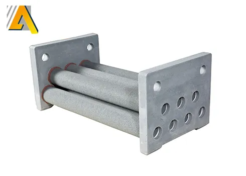
The tubular geometry is the defining characteristic that separates this filter category from the more commonly known flat ceramic foam filter, which most foundry technicians picture first when they hear “ceramic filter.” Where a flat foam filter presents metal with a single flat cross-section to pass through, a tubular cartridge wraps that filtration surface into a cylindrical shape, dramatically increasing the total surface area available for filtration within roughly the same footprint a flat filter would occupy in a filter box.
We find it helpful to explain this to newer foundry staff using a simple comparison: imagine trying to strain a large volume of liquid through a flat coffee filter versus a cylindrical filter cartridge of similar diameter. The cylindrical shape simply gives the liquid more surface area to pass through before it has to push through at any single point, which is exactly why tubular designs handle higher throughput without clogging as quickly.
| Filter Characteristic | Typical Specification Range |
|---|---|
| Outer diameter | 30mm to 90mm depending on model |
| Length | 150mm to 600mm |
| Wall thickness | 5mm to 15mm |
| Effective filtration surface area | 3 to 8 times greater than equivalent footprint flat filter |
| Operating temperature tolerance | Up to 1000°C for standard grades |
| Typical material composition | Silicon carbide, alumina, mullite, or foam-ceramic composite |
How Tubular Filters Remove Inclusions From Molten Aluminum
The filtration mechanism inside a tubular ceramic cartridge relies on several physical processes working together rather than a single simple straining action, and understanding these mechanisms explains why filter selection needs to match specific inclusion types a foundry is actually dealing with.
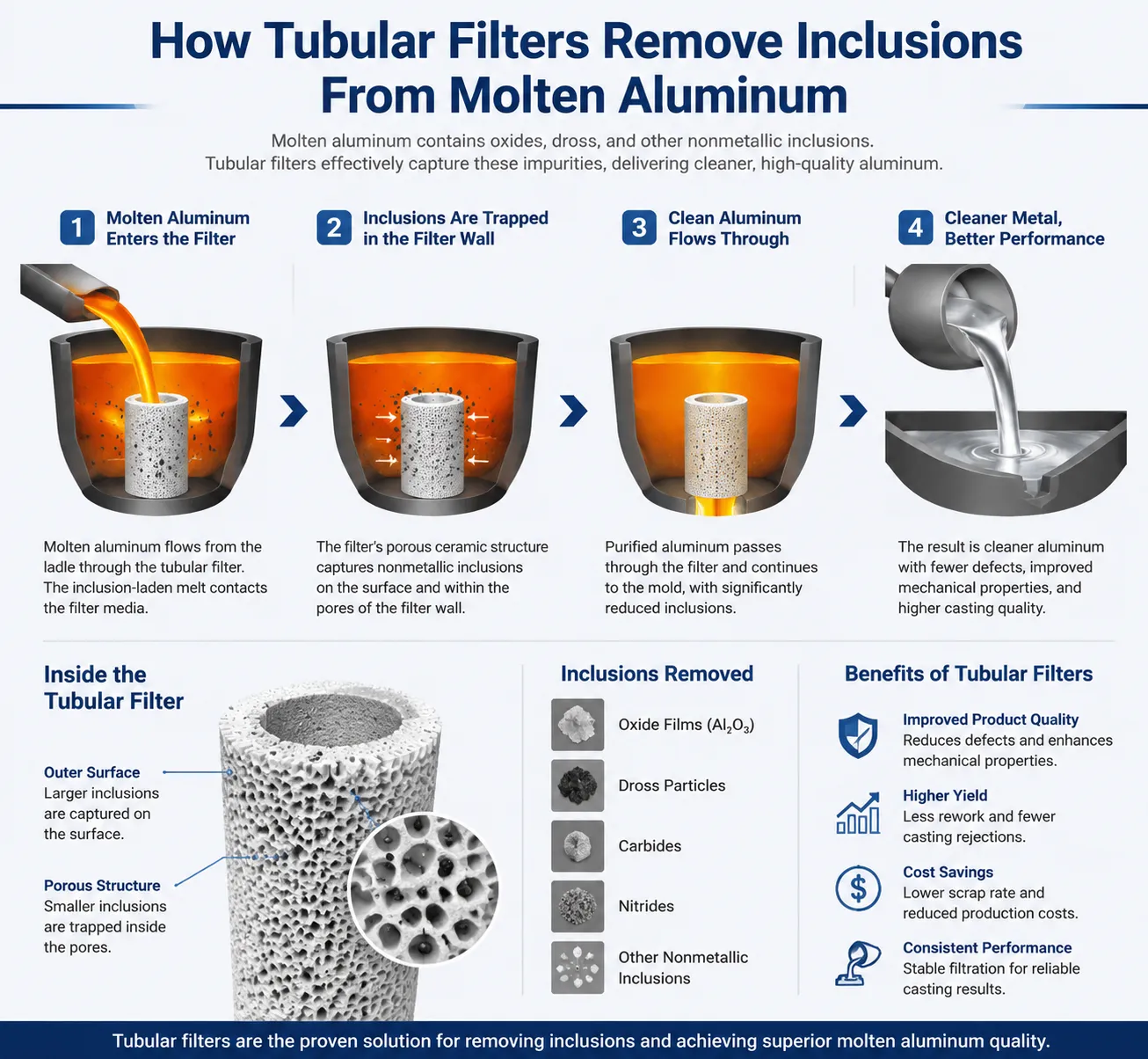
Mechanical straining catches the largest particles, those physically too big to pass through the pore network regardless of flow conditions. This is the most intuitive mechanism and the one most people picture when thinking about filtration generally.
Depth filtration captures medium and smaller particles as molten metal winds through the tortuous internal pore pathway inside the ceramic wall. Unlike straining, which happens at the surface, depth filtration traps particles throughout the entire thickness of the ceramic material, which is a major reason tubular cartridges with thicker effective walls tend to capture a broader range of inclusion sizes compared to thinner flat filters.
Cake filtration develops after a filter has been in service for a period, as trapped inclusions begin forming their own secondary filtering layer on the entry surface. This developing cake actually improves fine particle capture over time, though it also gradually increases flow resistance, which is part of why filters eventually need replacement even without visible damage.
Adhesion and surface interaction play a role too, particularly for oxide film fragments that tend to stick to ceramic surfaces due to surface energy differences between the oxide material and the ceramic substrate, capturing particles that might otherwise be small enough to pass through purely mechanical straining.
| Filtration Mechanism | Particle Size Range Addressed | Stage of Filter Life |
|---|---|---|
| Mechanical straining | Above 100 microns | Active throughout service life |
| Depth filtration | 20 to 100 microns | Active throughout service life |
| Cake filtration | Below 20 microns | Develops and strengthens over time |
| Surface adhesion | Oxide films, fine particulates | Active throughout, particularly early service |
Construction Materials and Manufacturing Process
The material a tubular cartridge is made from significantly influences its performance characteristics, thermal shock resistance, and suitability for different aluminum alloys and operating conditions.
Silicon carbide tubular filters offer excellent thermal shock resistance and mechanical strength, making them suitable for higher-throughput applications and situations where the filter experiences temperature fluctuation during startup and shutdown cycles. The tradeoff is generally higher cost compared to alumina-based alternatives.
Alumina-based tubular filters cost less and work well for general-purpose aluminum filtration applications where extreme thermal cycling isn’t a major concern. Many general foundry operations running standard alloy castings find alumina cartridges provide adequate performance at a more accessible price point.
Mullite composite filters sit between these two options, offering a balance of thermal stability and cost that appeals to mid-volume operations not requiring the premium performance characteristics of silicon carbide but wanting better durability than basic alumina products provide.
Manufacturing typically involves extruding a ceramic slurry mixture through a die to form the tubular shape, followed by controlled drying and high-temperature firing that develops the porous structure and mechanical strength needed to withstand contact with molten aluminum. Pore size and distribution get controlled during this manufacturing stage through the specific formulation of the ceramic slurry and firing parameters, which is why reputable manufacturers provide consistent pore size specifications batch to batch while lower-quality producers sometimes show more variation.
| Material Type | Thermal Shock Resistance | Relative Cost | Best Application |
|---|---|---|---|
| Silicon carbide | Excellent | High | High-volume, thermal cycling applications |
| Alumina | Moderate | Low to moderate | General purpose, standard alloy filtration |
| Mullite composite | Good | Moderate | Mid-volume operations balancing cost and durability |
| Foam-ceramic hybrid | Good | Moderate | Applications needing higher porosity, faster flow |
Tubular Cartridge Filters Compared to Foam and Plate Filters
Foundries evaluating filtration options need a clear comparison between the main filter formats available, since each brings distinct tradeoffs.
| Filter Type | Filtration Surface Area | Flow Capacity | Typical Service Life | Installation Complexity |
|---|---|---|---|---|
| Tubular ceramic cartridge | High (cylindrical geometry) | High | Long (multiple casting cycles common) | Moderate, requires dedicated housing |
| Flat ceramic foam filter | Moderate (single flat plane) | Moderate | Short to moderate (often single-use) | Simple, drops into standard filter box |
| Ceramic plate filter | Low to moderate | Lower | Short | Simple |
| Deep bed filter | Very high | Very high | Very long | Complex, larger footprint needed |
Flat ceramic foam filters remain the most widely used format across the industry due to low cost and simple installation, essentially dropping into a filter print positioned in the gating system. They work reasonably well for general sand casting and gravity die casting applications with moderate quality requirements.
Tubular cartridge filters justify their higher unit cost and installation complexity in situations demanding higher throughput, extended service life without replacement, or superior inclusion capture for critical castings like automotive structural components or aerospace parts where inclusion-related rejection carries significant cost consequences.
We generally advise foundries running high-volume continuous operations, particularly those feeding multiple mold cavities from a single filtration point, to seriously evaluate tubular cartridge systems even though the upfront investment runs higher, because the extended service life and reduced changeover frequency often produce lower total filtration cost per ton of metal processed once labor and downtime factors get included in the calculation.
Key Specifications Buyers Need to Understand
Procurement teams new to ceramic filtration often focus purely on price per unit without understanding the specifications that actually determine whether a filter performs adequately for their specific application.
Pore size, typically measured in pores per inch or PPI for foam-type ceramics, or in micron ratings for more precisely engineered cartridge designs, determines the smallest particle size the filter can reliably capture. Finer pore ratings capture smaller inclusions but also restrict flow rate and clog faster, requiring a balance based on the specific cleanliness requirements of the casting being produced.
Flow capacity, usually expressed in kilograms of aluminum per minute the filter can process while maintaining acceptable pressure drop, determines whether a given cartridge size matches your furnace throughput and pouring rate requirements. Undersized filtration relative to pour rate causes bottlenecking and can force metal around rather than through the filter media if pressure builds excessively.
Temperature rating confirms the filter can withstand your specific alloy’s processing temperature with margin for normal operational fluctuation, since running a filter consistently near its maximum rated temperature accelerates degradation and shortens usable service life.
Dimensional tolerance matters for proper fit within housing equipment, since a cartridge that doesn’t seat correctly can allow unfiltered metal to bypass around the filter media entirely, defeating the entire purpose of installing filtration in the first place.
| Specification | Why It Matters | Typical Buyer Question |
|---|---|---|
| Pore size / PPI rating | Determines minimum captured particle size | What inclusion size am I trying to remove? |
| Flow capacity (kg/min) | Matches filter to production throughput | What is my furnace pour rate? |
| Maximum operating temperature | Ensures safe margin above process temperature | What alloy and pouring temperature am I running? |
| Dimensional tolerance | Ensures proper seating in housing | Does this fit my existing filter housing equipment? |
| Compressive strength | Withstands metallostatic pressure without cracking | What is my expected metal head height during pouring? |
Filtration Efficiency and Pore Size Selection
Choosing the correct pore size represents one of the more technical decisions buyers face, and getting it wrong in either direction creates problems. Too coarse a rating lets damaging inclusions through, defeating the filter’s purpose. Too fine a rating restricts flow excessively and shortens service life through premature clogging.
| PPI Rating (or equivalent micron range) | Typical Inclusion Capture Capability | Common Application |
|---|---|---|
| 10-15 PPI (coarse) | Larger oxide films, refractory fragments above 150 microns | High-volume general castings, less critical applications |
| 20-30 PPI (medium) | Moderate inclusion sizes, 50-150 microns | Automotive components, general structural castings |
| 40-50 PPI (fine) | Fine inclusions, oxide particles below 50 microns | High-integrity castings, thin-wall applications |
| 60+ PPI (extra fine) | Very fine particulates, near-micron level capture | Aerospace, critical safety components |
We generally recommend foundries run inclusion analysis on rejected castings before selecting filter pore size, since guessing at the appropriate rating without data on actual inclusion size distribution in your specific defects often leads to either overspending on unnecessarily fine filtration or underspending and continuing to see the same defect pattern after installation.
System Components Beyond the Filter Cartridge Itself
A complete tubular ceramic cartridge filtration system involves more than just the ceramic element, and buyers evaluating a full system purchase should understand each supporting component.
The housing or filter chamber holds the cartridge in position and directs metal flow through it, typically constructed from refractory-lined steel designed to withstand contact with molten aluminum and repeated thermal cycling as filters get changed between production runs.
Sealing gaskets, usually ceramic fiber or similar high-temperature material, prevent metal bypass around the cartridge edges where it meets the housing, and gasket condition needs regular inspection since a degraded seal allows unfiltered metal to leak around the filtration media.
Preheating equipment matters significantly for tubular cartridges, since installing a cold ceramic filter directly into a molten metal stream causes severe thermal shock that can crack the filter before it even begins working properly. Most systems incorporate a preheating stage, either through a dedicated preheat oven or torch preheating immediately before installation, bringing the cartridge to a temperature close to the molten metal before contact occurs.
Flow control and monitoring instrumentation, including pressure differential sensors across newer automated systems, help operators track filter loading and identify when a cartridge approaches its practical service life limit before it becomes fully clogged and restricts production flow.
| System Component | Function | Maintenance Consideration |
|---|---|---|
| Filter housing/chamber | Positions cartridge, directs metal flow | Refractory lining inspection, wear monitoring |
| Sealing gaskets | Prevents unfiltered metal bypass | Regular replacement, inspection for degradation |
| Preheating equipment | Prevents thermal shock cracking | Temperature calibration, consistent preheat cycle timing |
| Pressure differential monitoring | Tracks filter loading and remaining service life | Sensor calibration, data logging for trend analysis |
| Support structure/frame | Holds housing in casting line position | Structural integrity checks, alignment verification |
Installation Configurations in Foundry Casting Lines
Tubular ceramic cartridge filters get installed at different points depending on the casting process and production layout, and each configuration has specific considerations.
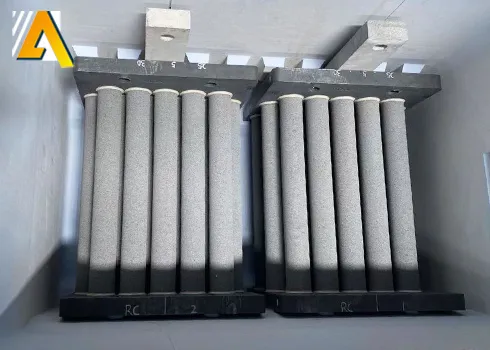
In-line launder filtration: Positioned within the metal transfer launder between the holding furnace and the mold or casting machine, this configuration works well for continuous casting and high-volume die casting operations where metal flows steadily rather than in discrete batches.
Ladle-mounted filtration: Some operations mount filtration directly at the ladle pour point, filtering metal as it transfers from ladle to mold, suited to batch casting processes like sand casting where pours happen intermittently rather than continuously.
Filter box integration within gating systems: For sand casting and investment casting applications, tubular cartridges can integrate into specially designed filter boxes positioned within the gating system itself, filtering metal during the actual mold-filling process.
Multi-strand distribution filtration: Larger continuous casting operations sometimes install tubular filtration at a central point before metal distributes to multiple casting strands, ensuring consistent filtration quality across all output regardless of which strand receives the metal.
| Installation Configuration | Best Suited Process | Key Consideration |
|---|---|---|
| In-line launder | Continuous casting, high-volume die casting | Requires stable, continuous flow rate |
| Ladle-mounted | Sand casting, batch pours | Preheat timing critical due to intermittent use |
| Gating system filter box | Sand and investment casting | Space constraints within mold design |
| Multi-strand distribution point | Large continuous casting operations | Central filtration simplifies quality consistency |
Benefits of Tubular Filtration for Casting Quality
We put together this benefits summary based on documented outcomes across foundry partnerships rather than generic manufacturer claims, since buyers deserve realistic expectations rather than inflated promises.
Higher inclusion capture rate per filter change: The larger effective surface area of tubular cartridges captures more total inclusion mass before reaching capacity compared to a similarly sized flat filter, translating into cleaner metal across a longer production run.
Reduced casting rejection rates: Foundries report measurable decreases in inclusion-related defects after switching to properly specified tubular filtration, particularly noticeable in thin-wall castings where even small inclusions cause visible surface defects or leak paths.
Extended production runs between filter changes: Because tubular cartridges handle higher total throughput before clogging, foundries running continuous or semi-continuous casting can extend production runs longer without interrupting for filter replacement, improving overall equipment effectiveness.
Better flow rate stability: The gradual, distributed loading pattern across a larger filtration surface tends to produce more stable flow rate throughout the filter’s service life compared to filters that clog rapidly and unevenly, which helps maintain consistent mold filling characteristics important for dimensional accuracy.
Reduced downstream machining and finishing costs: Cleaner cast metal with fewer trapped inclusions requires less rework during machining, since inclusions often cause tool wear and surface finish problems when machining operations encounter them.
| Benefit Category | Reported Improvement Range |
|---|---|
| Inclusion-related rejection reduction | 20% to 45% decrease |
| Filter change frequency reduction | 2 to 4 times longer service life versus flat filters |
| Machining tool wear reduction | 10% to 20% improvement in some documented cases |
| Flow rate consistency | Reduced variance throughout production run |
| Overall metal cleanliness (measured via inclusion count) | Significant reduction, varies by pore size selection |
Service Life, Wear Patterns, and Replacement Timing
Understanding how tubular cartridge filters degrade over their service life helps operators time replacement correctly, avoiding both premature changeouts that waste usable filter life and delayed changeouts that risk quality problems from an overloaded filter.
Early service life typically shows minimal flow restriction as the cartridge’s full pore network remains largely open. As production continues, trapped inclusions gradually accumulate within the pore structure and on the entry surface, progressively increasing flow resistance, which shows up as gradually increasing pressure differential across the filter if monitoring equipment is in place.
Mid-life operation often represents the filter’s peak effectiveness period, since the developing inclusion cake on the surface actually enhances fine particle capture even as it slightly restricts flow, a phenomenon well documented in filtration engineering generally and applicable to ceramic metal filtration specifically.
Late service life shows accelerating flow restriction as the pore network approaches saturation, and continuing to use a filter well past this point risks either excessive pressure buildup that can crack the ceramic structure or, in worse cases, inclusion breakthrough where previously captured material gets dislodged and passes through into the metal stream, effectively contaminating supposedly filtered metal.
| Service Life Stage | Flow Resistance Pattern | Filtration Effectiveness |
|---|---|---|
| Early (first 20-30% of service life) | Low, gradually increasing | Good, developing |
| Mid-life (30-70% of service life) | Moderate, stable increase | Peak effectiveness with cake filtration benefit |
| Late (70-90% of service life) | Rapidly increasing | Declining, approaching saturation |
| End of service life (beyond 90%) | Severe restriction or breakthrough risk | Unreliable, replacement needed |
We recommend foundries without pressure differential monitoring equipment establish a time-based or tonnage-based replacement schedule derived from initial trial periods tracking visible dross buildup and any quality metric changes, rather than running filters until visible problems appear in finished castings, since by that point some amount of defective production has likely already occurred.
Model of the Cartridge Filter Tube
| Model | Standard Model | Flow Rate (t/h) | Max process Capacity (t) | Heating Power(kw) | Residual Aluminum (kg) |
| EG-GD-7 | 7 | 7 | 700 | 54 | 700 |
| EG-GD-11 | 11 | 10 | 1100 | 90 | 800 |
| EG-GD-22 | 22 | 25 | 2200 | 135 | 1300 |
| EG-GD-28 | 28 | 30 | 2800 | 135 | 1300 |
| EG-GD-28 | 28*2 | 60 | 5600 | 180 | 3200 |
| EG-GD-22 | 22*3 | 75 | 6600 | 180 | 4500 |
Common Problems and Troubleshooting
Several recurring issues show up across foundries using tubular ceramic cartridge filtration, and recognizing these patterns speeds up problem resolution considerably.
Premature cracking, often traced back to inadequate preheating before installation, remains one of the most common and preventable problems. Thermal shock from installing a cold or insufficiently preheated cartridge into molten metal creates internal stress that can crack the ceramic structure immediately or create weak points that fail shortly after startup.
Metal bypass around the filter edges, usually caused by degraded sealing gaskets or improper seating during installation, allows unfiltered metal to pass around rather than through the filtration media, undermining the entire purpose of the installation while potentially giving operators false confidence that filtration is occurring when it effectively isn’t for a portion of the flow.
Inconsistent flow rate during casting, sometimes mistaken for a filtration equipment problem, can actually stem from uneven cartridge loading, incorrect pore size selection relative to the actual inclusion load in the incoming metal, or genuine equipment issues like housing misalignment.
Filter breakage during removal, particularly with cartridges that have been in extended service and become brittle from prolonged thermal cycling, requires careful handling procedures and appropriate tooling to avoid creating a mess of ceramic fragments in the housing that then require thorough cleaning before the next cartridge installation.
| Problem | Likely Cause | Corrective Action |
|---|---|---|
| Premature cartridge cracking | Inadequate preheating before installation | Verify preheat temperature and duration protocol |
| Metal bypass around filter | Degraded seal, improper seating | Inspect and replace gaskets regularly, verify seating procedure |
| Inconsistent flow rate | Uneven loading, wrong pore size, housing misalignment | Review pore size selection, check housing alignment |
| Filter breakage during removal | Extended service brittleness, improper removal technique | Follow manufacturer removal guidelines, avoid excessive force |
| Higher than expected rejection rate despite filtration | Incorrect pore size for actual inclusion profile | Conduct inclusion analysis, adjust pore size specification |
Cost Analysis and Return on Investment
Foundry managers evaluating a switch from flat ceramic foam filters to tubular cartridge systems need a realistic cost comparison that accounts for more than just the per-unit filter price.
| Cost Factor | Flat Ceramic Foam Filter | Tubular Ceramic Cartridge |
|---|---|---|
| Unit cost per filter | Lower | Higher |
| Typical service life per filter | Single casting cycle or short run | Multiple casting cycles, extended run |
| Housing/equipment investment | Lower, simple filter box | Higher, dedicated housing and preheat equipment |
| Labor cost for changeover | Frequent changeover labor | Less frequent, but preheat procedure adds time per change |
| Rejection rate cost impact | Higher due to lower inclusion capture | Lower due to superior capture efficiency |
| Total cost per ton of metal filtered | Often higher when including rejection costs | Often lower once volume justifies equipment investment |
We walk clients through a straightforward calculation when advising on this decision: multiply current rejection rate cost by production volume, then estimate the realistic rejection rate improvement a properly specified tubular system would deliver based on documented performance in comparable operations, and compare that savings against the incremental equipment and filter cost difference. For foundries running moderate to high production volumes with meaningful inclusion-related rejection rates, the payback period frequently falls within six to eighteen months, though very low-volume operations may find flat foam filters remain the more economical choice given their lower upfront commitment.
Procurement Considerations for Foundry Buyers
Buyers sourcing tubular ceramic cartridge filtration systems should request detailed technical documentation before committing to a purchase, particularly for first-time adoption of this filter format.
Request pore size distribution data with supporting test methodology rather than accepting a single nominal rating without verification, since manufacturing consistency varies between suppliers and a stated pore size doesn’t always reflect actual measured performance across a production batch.
Ask for flow capacity data specific to aluminum, since some manufacturers provide generic ceramic filter specifications derived from testing with other metals or even non-metallic fluids, which doesn’t necessarily translate directly to aluminum filtration performance given the metal’s specific viscosity and temperature characteristics.
Verify compatibility with your existing or planned housing equipment dimensionally before ordering in volume, since even minor dimensional deviations between supplier products can create sealing problems or improper fit that undermines filtration effectiveness.
Request sample cartridges for trial runs before committing to bulk procurement, allowing your specific operation to validate performance claims under actual production conditions rather than relying purely on supplier-provided data sheets.
| Procurement Checklist Item | Why It Matters |
|---|---|
| Verified pore size distribution data | Confirms actual filtration capability matches specification |
| Aluminum-specific flow capacity testing | Ensures relevance to your actual application |
| Dimensional compatibility verification | Prevents sealing and fit problems with existing equipment |
| Trial sample availability | Validates performance before bulk commitment |
| Batch consistency documentation | Ensures repeatable quality across ongoing orders |
| Technical support availability | Assists with installation and troubleshooting guidance |
Frequently Asked Questions
How is a tubular ceramic cartridge filter different from a standard ceramic foam filter?
A tubular cartridge uses a cylindrical geometry that provides significantly more filtration surface area within a compact footprint compared to a flat ceramic foam filter, resulting in higher flow capacity and longer service life before requiring replacement.
What pore size should I choose for automotive aluminum castings?
Most automotive structural and engine component castings work well with medium pore size ratings in the 20 to 30 PPI range, though thin-wall components or applications with stricter inclusion tolerance may benefit from finer ratings around 40 PPI.
How long does a tubular ceramic cartridge filter typically last in production?
Service life varies significantly based on inclusion load in the incoming metal, pore size selection, and production volume, but tubular cartridges commonly last two to four times longer than equivalent flat foam filters, sometimes handling multiple casting cycles or extended continuous runs before replacement becomes necessary.
Do tubular ceramic filters require special preheating before installation?
Yes, proper preheating is essential to prevent thermal shock cracking. Cold or insufficiently preheated cartridges installed directly into molten aluminum frequently crack immediately or develop weak points that fail early in service.
Can tubular ceramic cartridge filters be cleaned and reused?
Generally no, once a ceramic cartridge filter has captured its practical inclusion load, the trapped material cannot be effectively removed without damaging the ceramic structure, and reuse attempts typically compromise filtration reliability for subsequent production runs.
What happens if I select a pore size that’s too fine for my application?
An overly fine pore size restricts flow more than necessary, causing premature clogging, reduced throughput, and potentially forcing production slowdowns or increased pressure that risks cracking the filter structure before its intended service life is reached.
Is tubular cartridge filtration worth the investment for a small foundry operation?
Smaller operations with lower production volume and less stringent quality requirements may find flat ceramic foam filters more economical, since the higher upfront equipment and filter cost of tubular systems typically justifies itself through volume-based savings that lower-volume operations don’t generate as quickly.
How do I know when a tubular filter needs replacement during production?
Foundries with pressure differential monitoring can track rising resistance as a direct indicator, while those without instrumentation typically rely on established time or tonnage-based replacement schedules developed through initial trial monitoring of quality metrics and visible dross patterns.
Can tubular ceramic filters be used with aluminum alloys containing high magnesium content?
Most standard tubular ceramic filter materials handle magnesium-containing aluminum alloys adequately, though buyers should confirm chemical compatibility with their specific supplier since magnesium’s reactivity can interact differently with certain ceramic formulations compared to standard aluminum-silicon alloys.
What causes inclusion breakthrough in a tubular ceramic filter system?
Breakthrough typically occurs when a filter operates well beyond its practical service life, when pore size selection doesn’t match the actual inclusion size distribution in the incoming metal, or when physical damage to the cartridge creates unintended flow paths that bypass proper filtration.
Closing Thoughts From Our Filtration Experience
Tubular ceramic cartridge filtration represents a genuine upgrade path for foundries serious about reducing inclusion-related defects, but it isn’t automatically the right choice for every operation. We’ve seen smaller job shops waste money on oversized filtration systems that never get utilized to their capacity, while larger continuous casting operations running flat foam filters leave significant yield and quality improvement on the table by not evaluating tubular alternatives.
The decision ultimately comes down to matching filtration technology to actual production volume, quality requirements, and inclusion challenges specific to your operation. If persistent inclusion defects continue showing up in your rejection data despite existing filtration efforts, running a trial comparison between your current flat filter setup and a properly specified tubular cartridge system, backed by actual inclusion count data before and after, gives you concrete evidence rather than guesswork before committing to the larger equipment investment tubular systems require.