Roll Casting Nozzle Series
Products
PRODUCTS
CONTACT US
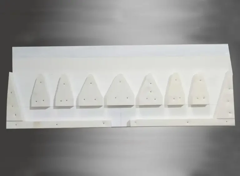
The Roll Casting Nozzle Series: made up of caster tip,spacers strips, ears, flow control box, and float funnel forms the precision flow-control assembly that determines molten aluminum distribution, thermal profile near the roll gap, and initial solidification behavior. Proper material selection, accurate geometry, tight assembly tolerances, and disciplined preheat plus surface treatment are decisive for producing defect-free strip, improving uptime, and reducing downstream processing.
Overview and technical context
Twin-roll continuous casting of aluminum strip places the feed nozzle assembly directly ahead of the roll gap. That assembly performs four tightly linked tasks: deliver molten metal uniformly across the width, dampen turbulent fluctuations, preserve thermal balance at the solidification front, and protect the roll surfaces from embedded abrasives or chemical attack. The typical nozzle assembly for strip production is modular, made of individual ceramic-fiber segments and supporting pieces that together create a controlled cavity before metal freezes against the water-cooled rolls.
1) What the nozzle assembly does and why it matters
In twin-roll strip casting the nozzle assembly sits between the tundish/headbox and the roll gap. Its effects are immediate: local flow uniformity across the width sets thickness and surface regularity, while local temperature control dictates the start of solidification and grain structure. Any variation in these variables translates into product defects—thickness variation, edge cracking, oxide inclusion, surface roughness, or embedded scratches from abrasive interaction. The nozzle assembly therefore functions both as a hydraulic element and a short thermal mold. Precision in its manufacture and strict control in its handling produce the greatest returns in product yield and reduced finishing cost.
2) Component anatomy and functional roles
2.1 Caster tip: the primary molding surface
Role. The caster tip provides the mold cavity that defines the initial sheet geometry and protects the rolls from direct contact with free liquid metal. It often forms the lower and upper lips of the feed cavity. The tip’s interior geometry, entrance lip, and lip chamfers manage flow velocity and shear near the roll surfaces.
Common construction. Manufacturers typically use ceramic-fiber composite or alumina-silicate fiber materials formed by vacuum or isostatic molding, then machined to dimension. These materials combine low thermal conductivity, thermal-shock resistance, and limited gas release during heating. The tip body commonly receives a thin boron nitride (BN) coating at the casting surface to reduce wetting and adhesion of oxides.
Critical design parameters.
-
width and profile tolerance (controls sheet width and uniformity)
-
lip radius and angle (affects shear and oxide folding)
-
cavity depth (controls residence time before solidification)
-
thermal mass and conductivity (affects cooling gradient)
Performance note. Hard and soft tip variants exist. Hard tips provide dimensional stability under abrasion but may transmit roll scratches. Soft tips tolerate slight indentation and reduce transfer of micro-scratches to the roll; selection depends on roll hardness and product finish requirements.
2.2 Spacers & strips: alignment, spacing, and transverse flow tuning
Role. Spacers and strips set the internal gaps between adjacent tip plates, creating the nozzle cavity geometry that yields a uniform across-width flow profile. They also assist in stepwise adjustment of width, and allow replacement of worn sections without changing the entire tip.
Material and fabrication. Typically made from high-purity fiberboard or alumina-silicate panels with CNC precision cutting. Tight thickness tolerances are essential; small deviations alter local flow or can cause localized overheating.
Practical note. Correct stacking order and indexing of spacer thickness across the width lets operators tune transverse temperature and flow, which is particularly valuable during grade transitions.
2.3 Ears: anchoring and sealing elements
Role. Ears keep tip plates aligned and fastened to the support frame. Two main types are used: soft ears and hard ears. Soft ears are compressible inserts that accommodate differential thermal expansion and minor misalignment. Hard ears provide rigid support, better location control, and are suited where dimensional precision is paramount.
Failure modes. Worn or broken ears lead to internal cavity leakage, cold spots, increased turbulence, and premature tip failure. Routine inspection prevents assembly drift.
2.4 Flow control box: a short conditioning chamber
Role. The flow control box sits behind or integrated with the tip assembly and performs bulk flow conditioning. It reduces pulsations, allows separation of coarser oxides, and provides a place for bubble escape or float control. Design may include shallow baffles, upward skimming gaps, or geometric transitions to reduce shear.
Operational effect. An effective flow control box smooths hydraulic disturbances from the tundish flow system and stabilizes flow into the narrow nozzle cavity. Its geometry directly influences casting speed capability and surface quality.
2.5 Float & funnel: feed metering and interface with upstream equipment
Role. The float and funnel manage how molten metal enters the flow control box and, ultimately, the nozzle cavity. The funnel centers feed into the cavity while float elements may carry skimming or gauging duties.
Design considerations. Floats often incorporate shallow weirs or overflow edges to separate slag and dross; funnels must avoid sharp transitions that promote turbulence. In many installations the float assembly integrates with degassing or filtration elements placed upstream.
3) Materials, fabrication and coatings
3.1 Typical materials and their rationale
-
Alumina-silicate ceramic fiber composites. Low thermal conductivity, resistance to oxidation, tolerance to thermal shock, and capacity for precise machining. Most common for tips and spacers.
-
High-purity aluminum oxide boards. Used for hard ears, supports, or strips requiring higher wear resistance.
-
Refractory bonding or interlayer coatings. Nano-coatings applied to high-wear surfaces prevent slag attachment and particulate erosion.
-
Boron nitride (BN) paint. A thin BN layer on working faces lowers metal wetting and reduces oxide adherence. BN application is routine in high-quality foil and thin-sheet production.
3.2 Manufacturing routes
-
Vacuum forming and sintering of short-fiber composites, followed by CNC finishing for dimensional control.
-
Compression molding for rigid ears or fixture parts.
-
High-precision water-jet or CNC cutting for spacer strips.
Manufacturers emphasize minimal outgassing during preheat and dimensional stability at operating temperatures.
4) Geometry, hydraulic behavior, and heat transfer considerations
4.1 Hydraulic design principles
-
Uniform across-width pressure drop. The nozzle cavity should have a nearly uniform pressure gradient from inlet to lip so that center-to-edge flow variations are minimized. Uneven pressure drop leads to thickness and surface irregularities.
-
Shear management near lips. The lip geometry sets shear at the roll interface; smooth, controlled shear reduces oxide folding and surface defects.
-
Residence time control. Deeper cavities increase residence time and allow more heat extraction prior to the roll gap; this can be useful for thicker strip but will affect casting speed.
4.2 Thermal considerations
-
Thermal mass and local cooling. Tip materials with lower conductivity provide a thermal buffer that slows heat extraction near the cavity, affecting solidification front location. This must be matched to casting speed and alloy thermal behavior.
-
Thermal gradients and stress. Non-uniform temperatures inside the tip produce internal stress and potential delamination; proper preheat schedules reduce those gradients.
5) Installation, preheating and surface treatments
5.1 Preheat protocol
Proper drying and preheat remove adsorbed water and bound moisture that can cause explosive spalling when molten metal is applied. Typical practice: controlled ramp heating to moderate temperature then soak. A common procedure used by foundries involves a ramp to roughly 250–300°C with a hold period to ensure dewatering of the fiber matrix. Reheat is required if parts remain idle.
5.2 Coating and surface conditioning
-
BN painting. Thin, even BN layers on inside faces reduce wetting and aid in strip release; reapply regularly after inspection.
-
Nano-coatings on high-wear areas. These reduce metal penetration into fibers and lower erosion rates.
5.3 Mechanical installation
-
Torque and clamp specification. Use manufacturer torque values for clips and clamps that hold ears and spacers. Improper tightening leads to gaps, leaks, and thermal runaway points.
-
Indexing and alignment. Use alignment pins or fixtures to ensure tip segments seat precisely; gap variation across the width must stay within the permitted tolerance band.
6) Process control, typical operating windows, and online monitoring
6.1 Operating variables to control
-
Casting speed. Faster speeds reduce residence time and shift the solidification front. Nozzle geometry and material must be appropriate for target speeds.
-
Headbox/tundish delivery rate. Must match nozzle design to avoid flooding or starvation.
-
Roll gap and roll cooling. Combined with nozzle behavior these variables set final strip thickness and grain size.
6.2 Monitoring tools
-
Thermocouples near the nozzle body. Monitor temperature trends during start-up and steady state.
-
Visual inspection cameras for lip area. Detect early oxide accumulation and lip erosion.
-
Flow meters and pressure transducers upstream. Provide feedback on clogging or sudden pulsations.
7) Common failure modes and troubleshooting
Below are frequent problems, likely causes, and recommended corrective actions.
Table: Failure modes, root cause and mitigation
| Observed symptom | Likely root cause | Immediate corrective action | Preventive measure |
|---|---|---|---|
| Surface scratches repeating along strip | Hard tip abrasives or embedded particles, roll-tip contact | Replace worn tip, inspect rolls for ridges | Use soft-Ear option, maintain filtration upstream |
| Edge cracking | Localized cold spots or uneven transverse flow | Adjust spacers near edge, check lip alignment | Regular spacer thickness audit, edge heaters if needed |
| Lip spalling or explosion | Moisture in tip, rapid thermal shock | Stop casting, allow slow cool, reheat and inspect | Strict preheat cycles between uses |
| Oxide folding and inclusions | High shear at lip or turbulent inlet | Smooth lip profile, reduce flow pulses | Re-profile tip, install upstream degasser or filter |
| Rapid wear of tip interior | High velocity abrasive flow or chemical erosion | Replace tip, review alloy impurity levels | Nano-coatings, BN reapplication, upstream filtration |
8) Maintenance, spare management, and lifecycle economics
8.1 Spare parts strategy
-
For continuous cast lines, keep a minimum stock of full-length caster tip sections equal to 1 to 3 production shifts of expected usage plus a set of standard spacer thicknesses.
-
Maintain an inventory of both hard and soft ears for rapid swaps.
8.2 Replacement criteria
-
Replace when lip geometry deviates beyond tolerance, or when material thickness at the working edge drops below specified residual. Inspect after any abnormal thermal event.
8.3 Lifecycle cost drivers
-
Material cost. Premium nano-coated tips cost more but extend life.
-
Operational downtime. Faster replacement times during night or shift changes reduce lost production. Plan for quick-fit clamps.
-
Energy and scrap. Optimized tip geometry reduces scrap and downstream finishing.
9) Quality checks, inspection methods, and acceptance criteria
9.1 Incoming acceptance tests
-
Dimensional check. Verify width, lip radius, cavity depth, and spacer thickness against drawing.
-
Density and porosity check. Confirm bulk density and absence of large voids in molded parts.
-
Surface finish. Ensure no cracks, delamination, or contaminant residues.
9.2 In-service inspection
-
Visual lip inspection every scheduled shift and after grade change.
-
Thermographic scan to detect unusual thermal patterns on the nozzle body.
-
Borescope or camera for internal cavity checks if geometry allows.
9.3 Acceptance thresholds (typical examples)
-
Lip radius tolerance: ±0.2 mm for foil-grade, ±0.5 mm for common sheet.
-
Spacer thickness tolerance: ±0.05 mm for foil operations.
10) Environmental, safety and handling notes
-
Never introduce water or wet cleaning solvents into parts before preheat; residual moisture causes steam spalling on contact with molten metal.
-
Wear appropriate PPE during tip handling due to brittle ceramic fragments and BN dust.
-
Dispose of spent tips following local regulations for ceramic and refractory waste; many suppliers offer recycling or take-back programs.
11) Procurement checklist and specification template
Minimal technical specification to request from suppliers
-
material composition and typical thermal properties (conductivity, max working temperature)
-
machining tolerances and machining method used
-
recommended preheat schedule and BN product used
-
recommended assembly fastener torque and ear type compatibility
-
lifetime expectancy for target casting speed and alloy family
-
sample testing certificate, manufacturing lot traceability
Contractual items to require
-
warranty on manufacturing defects and dimensional accuracy
-
delivery lead time and emergency fast-shipment options
-
replacement spare sets pricing and shelf-life guidance
12) Representative performance metrics and brief case notes
-
Yield improvement: A tightly matched tip-spacer set routinely reduces edge scrap by several percentage points in thin-gauge lines because of better transverse flow control.
-
Life extension with coatings: Operators report extended tip life and fewer oxide hang-ups after disciplined BN recoat cycles and nano-coating use.
13) Comparative tables and specification matrices
Table 1 — Component functions and key tolerances
| Component | Primary functions | Typical critical tolerances |
|---|---|---|
| Caster tip | Shape cavity; protect roll surface; set lip geometry | width ±1 mm; lip radius ±0.2 mm (foil) |
| Spacers & strips | Adjust cavity depth and transverse profile | thickness ±0.05 mm |
| Ears (soft/hard) | Fixation; thermal accommodation | fit clearance <0.5 mm |
| Flow control box | Flow smoothing and oxide separation | inlet diffuser angle ±2° |
| Float & funnel | Skimming and centered feed | overflow height ±1 mm |
Table 2 — Materials comparison (typical properties)
| Material class | Thermal conductivity (typ) | Max service temp | Typical use |
|---|---|---|---|
| Ceramic fiber composite | 0.12–0.20 W/mK | ~1200–1300°C | Caster tip, spacers |
| High-alumina board | 1.0–2.0 W/mK | ~1600°C | Hard ears, supports |
| BN coating (thin film) | negligible effect on bulk | stable to 1000°C | wetting reduction |
Sources: manufacturer technical notes and product pages.
14) Frequently asked questions
-
What differentiates a hard caster tip from a soft tip and which should I select?
Hard tips are rigid and resist abrasion; they are chosen for production lines where dimensional stability is paramount and rolls are hardened to reduce contact wear. Soft tips compress slightly under load, providing a buffer that can reduce the transfer of micro-scratches from brittle tip edges into roll surfaces. Choose hard tips for high-volume stable geometry and soft tips where roll finish quality is critical. -
Is boron nitride coating required?
BN coating is routine for foil and thin gauge production due to its low wettability. For thicker sheet grades some operators skip BN but coat key lip faces to limit oxide adherence. Follow supplier recommendations for coating thickness and reapplication frequency. -
How often should spacer thickness be audited?
At minimum perform a full spacer audit during each preventive maintenance outage and spot-check top-of-shift for lines producing foil-grade products. Small thickness drift can cause measurable edge-thinning. -
What preheat schedule prevents explosive spalling of tips?
A conservative approach ramps to roughly 250–300°C with a controlled soak to dehydrate fiber mats. Avoid sudden thermal shocks and reheat parts that have been idle. Manufacturer literature provides exact ramp rates for specific materials. -
Can nozzle geometry be tuned to increase casting speed?
Yes, a balance between cavity depth, lip geometry, and upstream flow conditioning lets some lines reach higher casting speeds. However higher speed reduces residence time for solidification and places more demand on downstream cooling. -
How do we detect internal delamination early?
Thermal imaging and periodic borescope inspection help. Delamination often first appears as a localized hot or cold patch during operation. -
What are common retrofit opportunities for older tip assemblies?
Upgrading to precision spacers, adding a modern flow control box, or using improved BN and nano-coatings are common retrofits that yield immediate quality and uptime benefits. -
Are there alloy-dependent considerations?
Yes. Low-melting alloys carry higher oxide flux and require more robust filtration. High-magnesium or silicon-containing alloys may increase erosion rates and need tougher materials or coatings. -
How to reduce oxide folding at the lip?
Smooth lip profile, reduce abrupt geometry changes upstream, control flow velocity, and maintain stable temperature across the width. Upstream degassing and filtration also help. -
What should procurement demand in test certificates?
Material composition, density, dimensional measurement sheet, and manufacturing batch traceability. Also request recommended preheating and handling instructions.
15) Final summary and recommended first steps for a foundry
The nozzle assembly is not a passive consumable but a mission-critical control element for any twin-roll strip caster. To realize stable, repeatable production and minimize defects, operators should pursue an integrated program that contains: careful material and supplier selection; disciplined preheat and BN application; tight tolerance control for spacers and ears; routine inspection with thermal and visual tools; and preauthorized spare kits sized for the line’s pace. The combination of right material, correct geometry, and proactive handling yields the best balance of surface finish, casting speed, and total cost of ownership.