Tubular or cartridge filter systems deliver very high filtration surface area per unit volume, enabling efficient capture of micron-scale inclusions and stabilizing flow into molds; when specified with the correct media, preheat practice and housing design, cartridge systems remove particles down to about 5 μm or smaller, extend service life relative to some surface filters, and provide a compact, modular solution for foundries that need reliable, repeatable melt cleanliness.
Product overview and intended use
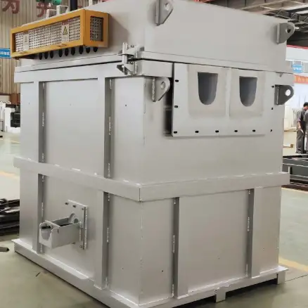
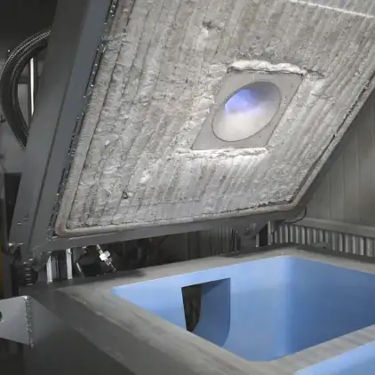
Tubular or cartridge filter equipment is a casthouse filtration solution that uses cylindrical filter elements installed inside a pressure- or gravity-fed housing. Molten aluminum passes through the filter cartridge wall and the internal porous media, so particles are captured both on the surface and within the depth of the element. These systems are suitable for transfers from furnace to ladle, ladle-to-pouring, or inline applications in gravity, low-pressure or some semi-continuous lines. Cartridge housings scale well for foundries that need modularity, quick element replacement, and high specific filtration area.
How tubular / cartridge filtration works
Dual mechanism: surface and depth capture
Cartridge media typically trap larger particles on the exterior surface and finer particles within the internal porous matrix. The metallic flow moves radially through the tube wall, so the effective filtration path is relatively long which increases capture probability for small inclusions.
Flow conditioning and head loss
Because many cartridges use graded porosity from outer to inner layers, the element conditions turbulent inflow into a steadier profile at the outlet. Designers balance porosity and surface area to limit head loss for a given pour height and flow rate.
Key performance variables include element outer diameter, wall thickness, media PPI or equivalent pore rating, and total active filtration area per housing. Practical design uses multiple parallel cartridges to manage head loss and service life.

Why choose tubular / cartridge systems
Advantages
-
Very high filtration surface area in a compact footprint, enabling finer media without excessive head loss.
-
Modular replacement, enabling quick cartridge swaps and lower downtime in many lines.
-
Good suitability for automated or semi-automated lines where cassette exchange and changeover can be engineered.
-
Ability to combine multiple media types inside a single cartridge for staged capture, improving overall cleanliness.
Limitations and considerations
-
Cartridge housings must be well sealed to prevent bypass; poor sealing negates filtration benefits.
-
Some cartridge media have limited thermal shock tolerance; preheat practice is mandatory.
-
For extremely high-volume pours, head loss may become limiting unless cartridge area is scaled accordingly.
Typical cartridge media and their properties
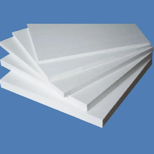
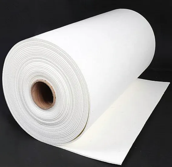
Cartridge elements can be made from foam ceramics, bonded granular products, sintered felt, or bonded silicon carbide. Selection factors include chemical compatibility, thermal shock resistance, mechanical strength and pore distribution.
Table 1: Common cartridge media options
| Media type | Typical composition | Strengths | Typical use |
|---|---|---|---|
| Foam ceramic (alumina) | Al₂O₃ open-cell foam | High porosity, deep-bed capture | General aluminum casting |
| Bonded silicon carbide | SiC granules bonded in matrix | Abrasion resistant, tougher | Heavy cycling, abrasive melts |
| Sintered ceramic fleece / felt | Bonded ceramic fibers | Fine polishing layer | Precision alloys and cosmetic parts |
| Bonded granular alumina | Alumina grains with binder | Controlled pore distribution | Tubular cartridges with staged depth |
References indicate cartridge systems allow finer filter media for a given flow rate due to their high contact surface.
Typical configurations and sizing guidance
Cartridge housings come in single-tube, multi-tube and duplex arrangements. Sizing requires matching the cumulative filtration area to the pour mass, permitted head loss and pour height.
Table 2: Sizing starting points
| Application class | Pour mass per pour (kg) | Typical cartridge count | Notes |
|---|---|---|---|
| Small batch / R&D | < 200 | 1–3 small cartridges | Use higher PPI polishing element |
| Medium production | 200–1000 | 4–12 cartridges | Modular banks allow staged replacement |
| High throughput | >1000 or continuous | Parallel banks or large cartridge arrays | Aim to limit head loss, consider duplex swap systems |
Sizing should begin with a trial run and RPT or inclusion counts to refine element count and porosity. Industry guidance stresses testing with your alloys and gating geometry.
Installation, preheat and commissioning
Preheat and thermal conditioning
Cartridge elements and housings must be preheated to remove moisture and avoid thermal shock. Typical preheat practice includes controlled warming of the element and housing to near-melt temperatures before first contact with molten metal. Failure to preheat can cause cracking and steam explosions.
Sealing and seating
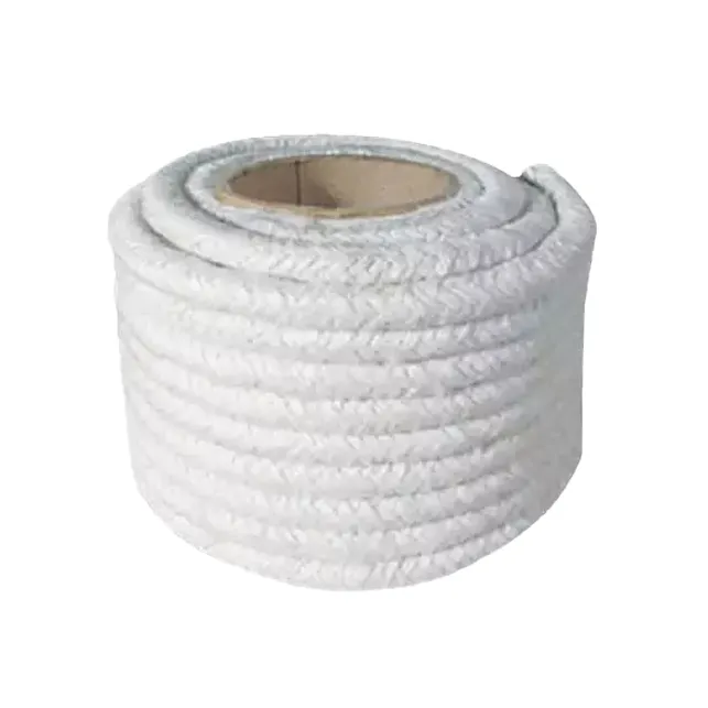
A robust gasket or refractory seal around each cartridge face is essential to prevent metal bypass. Use high-temperature gaskets that compress evenly and allow for thermal expansion. Ensure cartridge endcaps and housing interfaces are free of debris before installation.
Commissioning tests
-
Baseline Reduced Pressure Test (RPT) and inclusion counts prior to installation.
-
Trial pours with instrumentation logging pour rate and differential pressure across the housing.
-
Confirm no bypass by visual checks and metallographic sampling of poured parts.
Performance metrics and verification
Key KPIs to monitor:
-
Inclusion count and size distribution from metallographic sections.
-
Reduced Pressure Test improvements, recorded pre- and post-filtration.
-
Differential pressure across housing, logged per pour, to establish replacement thresholds.
-
First-pass machining yield and scrap rates.
To support purchasing decisions, ask suppliers for pressure drop curves, recommended media and shop trial data for your alloy.
Maintenance, element life and spare parts
Table 3: Recommended maintenance schedule
| Interval | Task |
|---|---|
| Before each shift | Visual inspection of seals, confirm preheat settings |
| After each shift | Remove dross accumulation in skimming areas, confirm instrumentation |
| Weekly | Inspect cartridge condition, check for hairline cracks or damage |
| Per element life | Replace element when head loss or pour rate drops below threshold, keep spare cartridges on hand |
Element life depends on inclusion load and PPI. Keep at least one full spare bank per critical line to avoid production interruptions.
Safety, environmental and regulatory considerations
-
Preheat in a controlled environment to eliminate moisture. Use ovens or jacketed housings per supplier instructions.
-
Capture and manage spent cartridges and trapped dross as industrial waste; many contain recoverable metal so recycling streams are available when processed safely.
-
Provide local exhaust ventilation and fume control near the filter station since skimming and fluxing generate fumes.
-
Use oxygen or gas monitors where inert gas systems are present, and ensure all gas storage complies with safety codes.
Troubleshooting common problems and corrective actions
Table 4: Troubleshooting matrix
| Symptom | Probable cause | Corrective action |
|---|---|---|
| Rapid rise in differential pressure | Filter loading or clogged cartridges | Replace top-stage cartridges, check upstream skimming |
| No improvement in inclusion counts | Bypass or poor sealing | Inspect seals and seating, verify element orientation |
| Cartridge cracking | Inadequate preheat or thermal shock | Increase preheat time and rate, check handling practices |
| Flow pulsation or irregular pour | Inconsistent flow distribution across cartridges | Check manifold design and nozzle sizing |
| Excessive erosion at outlet | High local velocities or abrasive inclusions | Add erosion-resistant nozzle insert or redesign flow path |
Document every corrective action and correlate with upstream practices such as degassing and skimming to find root causes.
Integration with the melt-treatment train
An effective melt-cleanliness strategy sequences processes so each step extends the life and effectiveness of the next. Typical train:
-
Degassing (rotary or vacuum) to remove dissolved hydrogen.
-
Skimming and fluxing to remove surface dross and oxides.
-
Cartridge / tubular filtration for staged deep and surface capture.
-
Final polishing filter or plate filter immediately before pour if needed.
Well-coordinated steps ensure cartridges capture particulates rather than heavy surface dross, which would otherwise clog elements prematurely.
Economic justification and return on investment
Filtration systems reduce scrap, lower rework, and increase first-pass accept rates. Cartridge systems are often cost effective in medium to high-value part production due to modular replacement and fine capture.
Table 5: Illustrative ROI snapshot
| Metric | Example input |
|---|---|
| Annual throughput | 2,500 tonnes |
| Pre-filtration scrap rate | 1.8% |
| Post-filtration scrap rate | 0.8% |
| Metal saved annually | 25 tonnes |
| Metal value per tonne | $1,800 (market dependent) |
| Annual metal value saved | $45,000 |
| Annual consumables and maintenance | $9,000 |
| Net annual benefit | $36,000 |
| Typical payback | 6 to 24 months depending on scrap reduction and local costs |
Use site-specific scrap rates and metal pricing to create an exact payback model for your foundry.
Product specification examples
Table 6: Representative cartridge filter housing and element specs
| Item | Typical value / option |
|---|---|
| Housing material | Steel shell, refractory-lined interior or high-silicon lining for melt contact |
| Cartridge element length | 200 mm to 600 mm typical, custom lengths available |
| Cartridge outer diameter | 50 mm to 150 mm typical |
| Media types | Foam ceramic (alumina), SiC bonded, sintered felt |
| Heating | External heaters for housing, optional induction preheat for elements |
| Instrumentation | Differential pressure transducer, thermocouple, HMI logging |
| Changeover | Manual clamp plate, hydraulic cassette, or automated duplex switch |
| Throughput | Scales from R&D ladles to multi-tonne lines with parallel banks |
Ask suppliers for element surface area per piece and pressure drop curves at your target flow rates.
Case notes
Case A: Precision die-cast supplier
A supplier of cosmetic housings retrofitted cartridge filtration upstream of the die and combined it with improved preheat practice. Results included a 35 percent reduction in surface blemish rework and a measurable improvement in RPT scores within eight weeks.
Case B: Medium automotive foundry
An automotive foundry used duplex cartridge banks to allow continuous production during element swaps. Cartridge staging reduced downtime by 70 percent compared with single-stage plate filters and delivered a payback in under 18 months due to reduced scrap and machining time.