Stalk tube filters are a practical and cost-effective method to capture inclusions during low pressure and gravity-fed aluminum casting, delivering measurable reductions in scrap rates and improvements in surface finish when matched to the right material, pore rating, and installation practice. They work by placing a ceramic filtering element at the base of the riser tube so molten metal is cleaned during each fill, and modern options include alumina grades, aluminum titanate, and silicon nitride to suit different alloys and duty cycles.
1. What stalk tube filters are and where they sit in a casting line
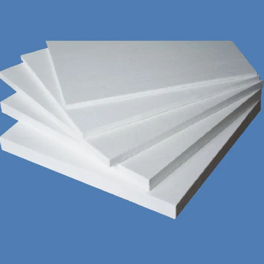
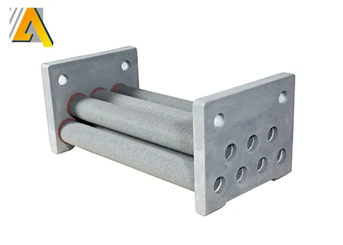
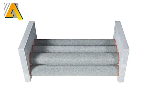
A stalk tube filter is a ceramic or engineered porous element positioned at the base of a riser or stalk tube in low pressure die casting and some gravity casting setups. The riser tube is the conduit that carries molten aluminum from a holding furnace or tundish into the mold cavity. By making the melt pass through a porous medium at the entrance to that tube, foundries capture non-metallic inclusions and coarse oxide fragments before they enter the die, which reduces internal defects, surface blemishes, and downstream rework.
2. Why foundries use stalk tube filtration: performance goals and quality metrics
Primary aims when adopting stalk tube filters
-
Lower inclusion counts in castings, which reduces scrap and machining rejects.
-
Produce laminar, controlled flow into the cavity to avoid turbulence-driven defects.
-
Protect tooling and die surfaces from abrasive particles, lengthening tool life.
-
Improve mechanical properties that are sensitive to inclusions, for example fatigue strength in wheels and structural castings.
Key performance metrics to track
-
Inclusion particles per unit volume measured by laboratory inspection or automated optical inspection.
-
Casting scrap rate and percentage of parts that require rework.
-
Surface roughness and porosity rates in finished castings.
-
Cycle-to-cycle repeatability of filtrate flow and pressure drop.
3. Common materials and how material choice affects lifetime and compatibility
Material selection is the single most important factor in filter lifetime and compatibility with specific alloys and process conditions. The market has converged around a handful of families with different trade-offs.
Table 1. Common stalk tube filter materials and high-level properties
| Material family | Typical advantages | Limitations | Typical applications |
|---|---|---|---|
| High-purity fused alumina (Al₂O₃) | Good chemical stability, established performance | Moderate thermal shock resistance | General aluminium casting |
| Aluminum titanate | Excellent thermal shock resistance, low expansion | Higher cost, specific grades required | High-cycle LPDC, variable temperature processes |
| Silicon nitride or SiAlON composites | Long life, strong against erosion | Costly, specialized handling | High abrasion environments, longer service intervals |
| Rigidized fibreglass or engineered lattice ceramics | Controlled flow paths, reproducible performance | Newer tech, different failure modes | Low-pressure casting where specific flow control is vital |
Sources in the industry note that aluminum titanate and silicon nitride offer superior resistance to thermal cycling and erosion compared with standard alumina grades, which can translate to extended service life in continuous or high-frequency operations.

4. Pore structure, graded porosity, and retention vs. pressure drop
Filtration efficiency is driven by pore size distribution, tortuosity in the ceramic matrix, overall porosity percentage, and the hydraulic path length through the element. Manufacturers offer filtration elements with different nominal retention classes. The design goal is to trap inclusions above a target size while maintaining an acceptable pressure drop that does not slow cycle times.
Table 2: Typical relationships (illustrative, subject to supplier specs)
| Nominal pore rating (µm) | Expected capture range (µm) | Typical pressure drop behavior | Common use |
|---|---|---|---|
| 5 – 10 | captures coarse micro-inclusions, oxides | low to moderate | fine casting finishes, aerospace-related parts |
| 10 – 30 | removes typical casting scale and dross particles | moderate | general purpose wheel casting, structural parts |
| 30 – 100 | removes larger debris and slag | low | initial bulk filtration, pre-filtering stages |
Suppliers control grain size and firing regimes to tune these properties. Some modern products use controlled lattice geometries to achieve reproducible pathways and predictable pressure drop characteristics.
5. Typical dimensions, mounting methods, and integration with riser tubes
Stalk tube filters are available in multiple outer diameters and lengths to fit existing riser tubes. Common integration methods include:
-
Press-fit into a machined recess at the base of the stalk tube.
-
Slip-fit with a ceramic-to-metal gasket that seals the joint and prevents by-pass.
-
Integral molded assemblies where the filter is part of a pre-fired stalk tube.
Preheating of the stalk tube and filter assembly is standard practice to prevent thermal shock cracking at first use. Manufacturer instructions typically include a controlled ramp to operating temperature.
6. Installation, preheating, and handling best practices
Steps to improve reliability and reduce early failures
-
Inspect the element visually for cracks and fines before installation.
-
Preheat both stalk tube and filter incrementally to operating range following manufacturer recommended profile.
-
Use appropriate ceramic gaskets and clamp methods to avoid mechanical stress concentrations.
-
Avoid hammering or force-fitting ceramics; use uniform axial compression when required.
-
Document the initial pressure drop and flow curve to create a baseline for future inspections.
Preheating matters because ceramics often retain moisture from storage or the environment; rapid exposure to molten aluminum can cause spalling or catastrophic fracture. Many vendors publish a recommended preheat sequence for their specific composition and geometry.
7. Inspection, failure modes and maintenance routines
Common failure modes and practical mitigations
-
Thermal shock cracking: reduce by controlled preheat, limit thermal excursions, prefer low-expansion materials.
-
Abrasion and erosion: select a higher-wear material, especially with high entrained oxides or when remelting sprues.
-
Clogging or bridging: monitor pressure drop, inspect for trapped dross, consider staged filtration upstream.
-
Leaks and bypass: ensure proper gasketing and fit, check for mechanical damage to the tube seat.
Routine checks
-
Measure pressure drop across the tube each shift and log changes.
-
Replace element when pressure drop reaches a predefined threshold or when visual inspection shows degradation.
-
Keep spares on shelf sized to expected replacement interval to avoid unplanned downtime.

8. Comparison with other filtration methods used in aluminum casting
Stalk tube filters are one of several options; the right choice depends on the application’s economics and quality targets.
Short comparative summary
-
Ceramic foam plate filters: excellent overall removal of fine inclusions, normally placed in launder lines or at the pour spout. They are widely used for whole-bath filtration but can require larger equipment footprints.
-
Box or plate filters in launder: good for centralized filtration in casthouses with larger melting and transfer systems.
-
Rigid lattice filters: new additive manufactured ceramics offer reproducible flow patterns and low particulate release, giving predictable behavior cycle-to-cycle.
-
Stalk tube filters: optimized for direct filtration during each mold fill, minimal footprint, high local protection and quick element swaps.
Decision factors include casting cycle time, alloy sensitivity, scrap cost, and shop floor layout.
9. How to select a stalk tube filter for a specific alloy and casting process
Selection checklist
-
Identify the target inclusion size to be removed based on part tolerance and end-use.
-
Evaluate the thermal profile and cycle frequency; for high cycles pick materials with excellent thermal shock resistance.
-
Consider chemical compatibility; some alloys with high reactive elements may require higher-purity or different ceramic chemistries.
-
Confirm mechanical mounting details to ensure there is no by-pass route and that thermal expansion mismatches are handled.
-
Decide on a cost-per-casting replacement target and match it to supplier life data.
When in doubt, request supplier flow vs. pressure drop curves and real-world service data for the exact alloy and cycle time. Several established suppliers publish application notes and technical bulletins to help match product to process.
10. Measurable benefits and a sample ROI calculation
Benefits to quantify
-
Reduced scrap rate (for many users this is the principal measurable benefit).
-
Lower machining rejects, fewer porosity-related failures.
-
Extended die life and less die maintenance due to abrasive particle reduction.
-
Improved customer satisfaction and fewer warranty claims tied to internal defects.
Sample ROI scenario (illustrative numbers)
Table 3: Simple example for one production line (annualized)
| Input | Value |
|---|---|
| Annual castings produced | 200,000 units |
| Current scrap rate (without stalk filter) | 3% (6,000 units) |
| Scrap rate (with stalk filter) | 1.5% (3,000 units) |
| Salvage saving per saved unit | $25 |
| Annual saved value | (6,000 − 3,000) × $25 = $75,000 |
| Annual cost of filters and spares | $10,000 |
| Net annual benefit | $65,000 |
| Payback | under one production year |
This example demonstrates that even modest reductions in defect rate translate quickly into payback for filters when scrap or rework costs are significant.
11. Manufacturing quality controls and testing standards
Good manufacturing practices and inspection procedures typically include
-
Raw material certification and batch traceability.
-
Controlled mixing, forming and firing profiles to guarantee consistent porosity and strength.
-
Leak testing and dimensional inspection post-firing.
-
Pressure drop and porosity characterization using standardized air or liquid flow tests.
-
Mechanical strength testing for compressive and tensile-like loads to ensure handling survivability.
Leading suppliers provide technical data sheets, handling instructions and sometimes sample test blocks to qualify material behavior under the customer’s process conditions.
12. Environmental, health and safety considerations
Safe handling notes
-
Ceramic dust from broken or cut elements can be hazardous; use local extraction and respiratory protection during handling of raw elements.
-
Avoid rapid quenching of hot ceramics; they may fracture and release sharp fragments.
-
Dispose of spent ceramic elements according to local environmental regulations; many are inert but still subject to industrial waste rules.
-
Train operators on proper preheating and on recognizing compromised parts.
13. Troubleshooting: common problems and remedies
Problem: Early cracking on first use
-
Likely cause: residual moisture or too-rapid thermal shock.
-
Remedy: revise preheat protocol, hold at intermediate temperature to drive off moisture.
Problem: High pressure drop after a few cycles
-
Likely cause: trapped dross or excessive fines upstream.
-
Remedy: check upstream launder filtration, consider coarser pre-filter stage.
Problem: Bridging and partial flow blockage
-
Likely cause: inappropriate pore size for the inclusion load or poor flow path.
-
Remedy: upsize pore rating or introduce staged filtration.
Problem: Shorter than expected life under abrasive conditions
-
Likely cause: material selection mismatch.
-
Remedy: test higher-wear materials such as SiAlON or silicon nitride-based elements.
14. Reference tables and technical data at a glance
Table 4: Quick selection cheat sheet
| Process parameter | Recommended action |
|---|---|
| Short cycle LPDC with high thermal swings | Use aluminum titanate or SiAlON |
| High inclusion load from remelt operations | Add upstream coarse filter and choose erosion-resistant element |
| Need for ultra-fine internal cleanliness | Select lower pore rating and accept higher pressure drop |
| Tight footprint and minimal changeover time | Choose plug-in stalk tube elements sized to existing riser tubes |
Table 5. Example installation checklist
| Step | Verification |
|---|---|
| Visual inspect element | No cracks, no loose fines |
| Preheat procedure | Temperature ramped to recommended setpoint |
| Seat gasket | Intact, correct material |
| Pressure drop baseline | Logged and stored |
| Spare element | On site, same part number |