Aluminum degassing systems are essential in the production of high-quality aluminum alloys, ensuring purity and structural integrity. The Molten Aluminum Degassing Unit is a vital piece of equipment used in aluminum manufacturing to remove dissolved gases, primarily hydrogen, that can cause defects in aluminum products. This system contributes directly to the final product’s strength, durability, and overall performance in various industries, including automotive, aerospace, and construction. Implementing advanced degassing technologies like the Molten Aluminum Degassing Unit significantly enhances the quality and consistency of aluminum alloys, making them suitable for high-performance applications.
What is Aluminum Degassing?
Aluminum degassing is the process of removing hydrogen and other dissolved gases from molten aluminum. These gases can be introduced during the melting process or as a result of contamination.
Hydrogen is the most common contaminant in molten aluminum, and its removal is essential to prevent gas porosity and other defects in the final product.
How Does a Molten Aluminum Degassing Unit Work?
A Molten Aluminum Degassing Unit utilizes a variety of methods to remove gases, including mechanical stirring, vacuum degassing, and the use of specialized fluxes or degassing agents.
The equipment typically consists of a degassing chamber, a gas injection system, and a filtration system designed to remove contaminants from the aluminum.
Parameters of Online Degassing unit:
| Max Degassing flow MT/H |
15 MT/H | 35 MT/H | 65 MT/H |
|---|---|---|---|
| Degassing Box Standard | 1 room 1 rotor (1B1R) | 2 rooms 2 rotors(2B2R) | 3 rooms 3 rotors(3B3R) |
| Degassing box structure | 1 draining outlet & 1 deslagging outlet | 2 draining outlets & 1 deslagging outlet | 3 draining outlets 1 deslagging outlet |
| Lifting System | Hoisting type | Rotor mechanical lifting | cover hydraulic lifting |
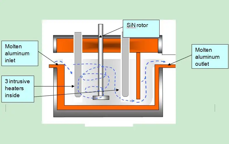
Operation Schematic Diagrams:
Why degassing matters for aluminum castings
Hydrogen in liquid aluminum dissolves in the melt and then forms gas pores during solidification. Those pores reduce tensile strength and fatigue resistance while increasing scrap and rework. Non-metallic inclusions, oxide films, dross and entrained slags also create stress concentrators and surface defects. Effective degassing reduces both gas porosity and inclusion count, which improves mechanical properties, surface finish, and machinability. When combined with proper filtration before mold filling, degassing supports predictable casting performance and higher yield.
Fundamentals: hydrogen solubility and porosity formation
-
Hydrogen solubility in aluminum increases in the molten state and drops drastically on solidification, causing dissolved hydrogen to nucleate into bubbles.
-
Primary mechanism for porosity formation is hydrogen diffusion to nucleation sites during cooling, often aggravated by turbulent pour and inadequate degassing.
-
Measurement metrics commonly used are hydrogen content in ppm (parts per million) and related indices such as Density Index and Reduced Pressure Test (RPT) results. Managing melt hydrogen below target ppm depends on alloy, casting geometry, and downstream requirements.
Key control variables that influence hydrogen removal efficiency include melt temperature, gas type and flow rate, rotor speed and geometry, degassing time, and melt volume treated per cycle.
Degassing methods: comparative overview
The main industrial approaches used in modern cast houses are summarized in the table below.
Table 1: Comparison of common degassing methods
| Method | Typical use cases | Mechanism | Strengths | Limitations |
|---|---|---|---|---|
| Rotary inert gas injection (rotor degassing) | High-volume casthouses, die casting, continuous casting | Rotor creates fine inert gas bubbles (argon, nitrogen) that capture hydrogen and buoy them to the surface | High throughput, well proven, good for inclusion flotation | Rotor wear; correct rotor geometry and gas dryness required |
| Flux degassing (salt flux tablets or powders) | Repair shops, small batches, secondary cleaning | Salt flux floats oxides and entrained dross to the surface, with some gas removal | Simple to apply, low capital cost | Flux residues require handling; limited gas-removal compared with rotary |
| Vacuum degassing | High-spec aerospace or specialty alloys | Lower pressure helps gas escape from melt; often combined with stirring | Excellent hydrogen reduction, no chemical flux residues | High capital cost, slower cycle times |
| Ultrasonic degassing | Research, niche high-performance uses | High-frequency vibrations coalesce bubbles and drive them out | Low physical contact wear, potential for fine-bubble control | Technology still emerging for full-scale foundries |
| In-line ladle/static mixers | Continuous process lines | Physical contactless mixing and bubble contact for hydrogen pick-up | Simple integration for some lines | Lower removal efficiency than rotary for heavy loads |
References and laboratory studies show rotary degassing provides a favorable balance between throughput and hydrogen removal for many industrial casting operations. Vacuum systems deliver the lowest hydrogen but at significantly higher cost per tonne.
How a molten aluminum rotary degassing unit works
A rotary rotary degassing unit typically includes: a drive and boom to lower a graphite rotor into the melt, a rotor head with designed impeller pockets, a dry inert gas supply (argon or nitrogen) with flow control, automated lift and rotation controls, and a control panel that permits programming of rotor speed, gas flow and treatment time. The rotor spins, breaking gas flow into fine bubbles throughout the melt volume. Hydrogen transfers from the liquid to the bubble surface and then the bubble rises toward the melt surface. Inclusions and oxides tend to attach to bubbles or migrate to the slag layer, where skimming removes them.
Important practical points:
-
Use dry, oil-free gas to avoid introducing contaminants.
-
Optimize rotor immersion depth and rotation speed for the treated melt volume.
-
Monitor hydrogen content by sampling or in-line sensors when available.
For many operations, combining rotor treatment with controlled fluxing produces the cleanest melt before final filtration and mold filling.

Flux degassing: chemistry and handling
Flux compositions for aluminum degassing commonly include chlorides and fluorides in a salt matrix. These materials help break oxide films, promote coalescence of non-metallic inclusions, and aid floating of dross. Flux is often applied in tablet or granular form. Operators must follow strict handling and PPE rules because some flux constituents can be corrosive or produce fumes.
Best practices:
-
Use certified flux formulations intended for the alloy family.
-
Apply flux at recommended temperature windows so it flows correctly and contacts contaminants.
-
Remove flux residues and manage spent flux and dross as industrial waste in compliance with local regulations.
Flux provides strong inclusion-cleaning performance but should not be relied upon solely for hydrogen removal in high-volume production lines.
Filtration synergy: ceramic foam filters and inline filtration
Degassing reduces dissolved gases; filtration removes non-metallic inclusions and aids laminar flow during mold filling. Ceramic foam filters remain the industry standard for aluminum casthouses due to their porous structure that captures particles while establishing more controlled flow.
Table 2: Typical ceramic foam filter properties
| Property | Typical range | Effect on casting |
|---|---|---|
| PPI (pores per inch) | 10, 30 | Lower PPI gives higher flow; higher PPI traps finer inclusions |
| Composition | Alumina, silicon carbide, zirconia variants | Choose based on alloy reactivity and melt temperature |
| Max continuous temp | 1000 – 1200°C | Matches aluminum processing needs |
| Thickness | 25 mm to 75 mm | Thicker filters provide higher capture but increase head loss |
Place filters immediately downstream from the degassing unit so that de-gassed, cleaner metal flows through filtration before pouring. Filtration reduces inclusion load in the die or mold and prevents reintroduction of surface dross.
Process control: key parameters and monitoring
Reliable degassing depends on repeatable control of five parameter groups:
-
Gas type and purity
Use high-purity, dry argon when maximum hydrogen removal is needed; nitrogen may be acceptable for less demanding alloys. Gas moisture must be controlled to parts per million. -
Rotor geometry and speed
Rotor design determines bubble size distribution. Smaller bubbles increase contact area per unit volume, accelerating hydrogen transfer. -
Treatment time and melt turnover
Target melt residence time within the degassing zone so that the majority of the melt experiences adequate bubble contact. -
Melt temperature
Keep temperature within the alloy recommended range; excessive temperature raises hydrogen solubility while low temperature increases viscosity and slows bubble rise. -
Sampling and verification
Use reduced pressure test or hydrogen-in-liquid sensors to confirm hydrogen levels are within specification prior to pour.
Operators should document parameter setpoints for each alloy and casting line to support repeatability.

Typical technical specifications to consider when selecting a degassing unit
Table 3: Example technical specification sheet (reference configuration)
| Item | Typical value or option |
|---|---|
| Unit type | Rotary inert gas degasser |
| Treatment capacity | 200 kg to 5,000 kg per hour (model dependent) |
| Rotor material | Graphite, coated graphite, ceramic options |
| Motor power | 0.75 kW to 7.5 kW depending on rotor size |
| Gas supply | Argon or nitrogen, 99.995% recommended |
| Gas flow control | Mass flow controllers or precision needle valves |
| Control | PLC with recipe capability and HMI |
| Safety | Overload protection, emergency lift, gas leak detection |
| Filtration integration | Filter box or in-line filter holder for ceramic foam filters |
Sizing the unit requires matching capacity to ladle volumes and desired cycle time. For continuous lines, select models rated above peak throughputs.
Maintenance and parts lifecycle
Common wear items:
-
Graphite rotor bodies and impellers; typical replacement interval depends on duty cycle but plan for seasonal replacement in heavy-use shops.
-
Seals, bearings, and gas fittings; schedule periodic inspection for leaks and contamination.
-
Control components and sensors; keep spare PLC modules if feasible to reduce downtime.
Maintenance tips:
-
Keep a spare rotor to swap during maintenance.
-
Use dry gas filtration and oil-free compressors to protect the rotor and gas lines.
-
Record run hours and metallurgical outcomes to predict parts replacement by trend.
For higher rotor life consider coated rotor options or corrosion-resistant composite rotors where alloy chemistry accelerates wear.
Safety, environmental and regulatory considerations
-
Fume management: Fluxing and surface skimming produce particulate and gaseous emissions; local exhaust ventilation and fume scrubbing often required.
-
Waste handling: Spent flux, dross, and contaminated filters must be treated or recycled according to local waste codes. Some flux components include chlorides; manage corrosion and environmental risk accordingly.
-
Gas safety: Argon and nitrogen are asphyxiants. Provide oxygen sensors and proper area ventilation near gas storage and unit operation zones.
-
Operator PPE: Heat-resistant gloves, face shields, and respiratory protection where required for fluxing operations.
Always consult local regulations for permissible emission levels and hazardous waste rules.
Measurement and quality assurance protocols
Common in-plant tests and measurements:
-
Reduced Pressure Test (RPT): Melt sample solidifies under vacuum to reveal porosity; widely used to compare melt quality before and after treatment.
-
Hydrogen titration: Laboratory gas analysis of hydrogen in melt (ppm).
-
Visual and X-ray inspection: For finished castings to verify porosity and inclusion distribution.
-
In-process sampling: Extract representative melt samples after degassing and prior to pour.
A valid QA plan includes pre- and post-degassing measurements, control charts for hydrogen ppm, and acceptance criteria tied to customer specifications.
Troubleshooting common issues and corrective actions
Table 4: Troubleshooting checklist
| Symptom | Possible cause | Immediate corrective action |
|---|---|---|
| Incomplete hydrogen reduction | Gas moisture, low rotor RPM, insufficient treatment time | Check gas dryness, increase rotor speed or treatment time, verify gas flow |
| Excess rotor wear | Abrasive inclusions, high rotor immersion depth | Inspect rotor design, lower immersion depth if safe, switch to coated rotor |
| Flux residues in melt | Excess flux or incorrect temperature | Reduce flux amount, check melt temperature window, skimming |
| Poor filter life | High inclusion load, incorrect filter PPI | Re-evaluate degassing efficiency, use coarser initial filter then fine |
| Variability between shifts | Inconsistent recipes or operator practice | Lock recipes in PLC, training, institute pre-shift checks |
Record deviations to refine control limits and recipe parameters.
Economic considerations and return on investment
Cost items to model:
-
Capital expenditure for degassing unit, installation, gas handling, and filtration hardware.
-
Operating expense: inert gas usage, power draw, rotor wear parts, flux consumption and disposal, labor.
-
Savings: reduced scrap, fewer rework cycles, improved customer acceptance, higher productivity and potential premium pricing for certified quality.
Table 5: Example ROI snapshot
| Metric | Value example |
|---|---|
| Annual melt throughput | 5,000 tonnes |
| Scrap reduction | 1.5% to 0.5% (post-degassing) |
| Annual scrap savings | 50 tonnes saved |
| Estimated payback | 12 to 24 months depending on local metal prices and labor rates |
Accurate ROI calculations require site-specific inputs for metal value and existing scrap rates.
Integration and installation tips
-
Place the degassing unit between furnace/ladle transfer and pouring station to minimize recontamination.
-
Ensure gas piping uses dry lines and oil-free compressors. Include point-of-use gas filtration and proper pressure regulators.
-
Provide space for rotor maintenance with overhead lifting and clearances.
-
Consider integration with data acquisition and SPC systems to log each treatment cycle for traceability.
Emerging technologies and research directions
Industry research continues on rotor design optimization and alternative degassing modes. Recent studies highlight improved refining when rotor geometry produces very small bubble sizes through higher shear or optimized impeller shape, which increases bubble surface area and boosts hydrogen diffusion rate. Ultrasonic and hybrid vacuum-rotor systems are under trial in specialty casting environments for even lower hydrogen content without heavy flux use.
Product differentiation: what to look for in a supplier
When comparing degassing systems evaluate:
-
Rotor technology and material options.
-
Control system with recipe storage and data output for traceability.
-
Integration capability with existing ladles and filtration.
-
After-sale support, spare parts lead time, and availability of local service engineers.
-
Safety and compliance documentation.
High-quality suppliers will provide performance curves for hydrogen reduction against treatment time for specific rotor and gas settings, enabling confident sizing.
FAQs
What level of hydrogen reduction can a rotary degassing unit achieve for aluminum?
Which inert gas should be used, argon or nitrogen?
How often should the graphite rotor be replaced?
Can flux fully replace a degassing unit?
Where should the ceramic foam filter be installed relative to the degasser?
Is vacuum degassing worth the extra cost?
How do I verify degassing performance in production?
What are common operator mistakes that reduce degassing effectiveness?
Can ultrasonic systems be retrofitted into existing lines?
What documentation should a supplier provide?
Case: A mid-sized foundry replaced manual flux-only practice with a rotary degasser and ceramic filter combination. Over 12 months scrap from porosity-related rejection fell by roughly one percentage point, and machining scrap decreased, leading to a payback under 18 months.
Packaging, commissioning and training offer checklist
When procuring a unit request:
-
On-site acceptance test with customer alloys.
-
Complete operator training manual and hands-on sessions.
-
Spare rotor and consumables kit.
-
Maintenance schedule and remote diagnostic capability.
-
Data export capability for SPC and traceability.
Implementing a modern molten aluminum degassing unit yields measurable reductions in dissolved hydrogen and non-metallic inclusions, improving casting yield, mechanical performance, and downstream processing efficiency; for medium to large cast houses this equipment typically reduces scrap rates and rework while raising finished part consistency, provided the unit is sized correctly and operated under controlled process parameters.