A high-purity graphite cone provides precise melt-control, low-wetting contact, long service life and consistent dimensional stability for aluminum casting operations; when specified with production-grade graphite, correct surface finish and matched sealing hardware, the cone reduces leakage, protects downstream filters and degassers, and contributes directly to improved yield and lower scrap rates in precision foundries.
Product synopsis and target uses
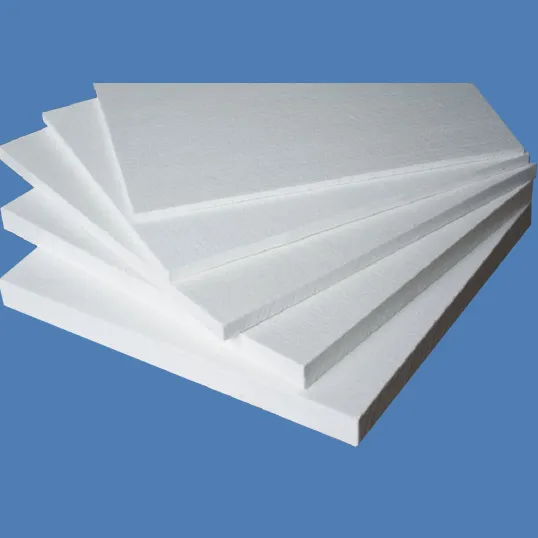
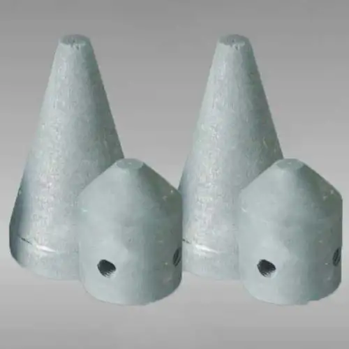
A graphite cone is a shaped, machined component used in molten aluminum flow-control assemblies, filter boxes and pouring nozzles. This component functions as a tapered stopper, a seat for a stopper rod, or a plug in a filter box, providing a tight shutoff or calibrated leakage path depending on the design. Intended strictly for aluminum-foundry applications, the graphite cone performs best where low chemical reactivity, thermal conductivity and dimensional accuracy are required. Key use cases include bottom-pour ladles, plate-type filter boxes, cartridge housings and sample extraction fixtures.
Specification:
| Items | Length | Shape | Package | Special Package |
| Tap out cone | 20-400mm | Cone shape / cylinder / open shape | 50-100pcs/box | As required |
Why graphite cones matter in aluminum casting
Graphite cones deliver three operational advantages that matter to process engineers:
-
Low metal wetting reduces sticking and eases skimming or removal at service intervals. This keeps interfaces clean and limits inclusion formation on the cone face.
-
High thermal conductivity and stable dimensional behaviour during heating and cooling mean the cone presents reliable seating geometry during every pour cycle. This improves shutoff repeatability and reduces uncontrolled leakage.
-
Controlled porosity and homogeneous density reduce spalling risk when the part undergoes rapid thermal change from room temperature to molten-metal contact. Properly specified graphite cones maintain mechanical integrity across many cycles.
Those three outcomes translate into better melt cleanliness, fewer filter blockages further downstream and lower total cost of ownership when compared with some ceramic or metal alternatives.
Principal material properties and why they work
Graphite is used widely in non-ferrous foundries because of a set of complementary physical and chemical attributes. The table below summarizes key parameters engineers should require from graphite cones.
Table 1: Typical graphite properties for foundry cones
| Property | Typical value or range | Engineering effect |
|---|---|---|
| Apparent density | 1.60 to 1.85 g/cm3 | Higher density improves mechanical strength and reduces porosity |
| Open porosity | 5 to 15% | Low porosity reduces metal penetration and spalling risk |
| Thermal conductivity | 80 to 200 W/m·K | Rapid heat distribution reduces thermal gradients |
| Coefficient of thermal expansion | ~4 to 8 ×10^-6 /K | Low expansion keeps sealing geometries stable |
| Oxidation onset | ~450 to 600 °C in air | Use protective atmosphere or coatings to manage oxidation |
| Graphite purity | 90 to 99.9% C (depending on grade) | Higher purity minimizes contamination risk in the melt |
Selecting the right bulk density and porosity profile affects wear life, sealing ability and compatibility with high-purity aluminum alloys. For many shop-floor uses, near-isostatic pressed high-purity graphite offers the best combination of dimensional precision and durability.
Manufacturing methods and quality control
Graphite cones are produced by one of the following routes:
-
Machining from extruded blocks or isostatically pressed billets. This yields tight dimensional control and smooth surface finish.
-
Precision molding followed by curing and high-temperature graphitization for complex shapes or integrated ribs.
-
CMC (computerized machining centre) finishing for critical sealing faces and threaded features.
Quality control checkpoints during production:
-
Dimensional verification using calibrated gauges and CMM inspection.
-
Porosity and density sampling using Archimedes or immersion testing.
-
Surface roughness measurement of sealing faces (Ra target recommended in the next section).
-
Microstructural inspection and carbon purity assay for any potential alloy contamination issues.
Manufacturers commonly offer optional impregnations or surface coatings (for example, anti-oxidation or boron-nitride wetting reducers) to enhance service life in particular environments. Request a manufacturer’s certificate for density, apparent porosity and dimensional tolerances before accepting production lots.
Geometry, tolerances and fitment practice
The cone geometry determines sealing performance and flow behaviour. Typical geometric features include nominal cone angle, seat diameter, skirt length and mounting thread or bayonet features.
Table 2: Recommended geometric control and surface finish
| Feature | Recommended tolerance | Notes |
|---|---|---|
| Seat diameter | ±0.05 mm for precision seats | Tight control avoids bypass leakage |
| Cone angle | ±0.2 degrees | Controls contact profile and sealing pressure |
| Skirt length | ±1.0 mm | Affects depth of engagement and support |
| Surface roughness Ra (sealing face) | 0.2 to 0.8 μm | Smoother faces reduce leakage and improve gasket life |
| Thread concentricity | ≤0.1 mm TIR | For threaded mounting ensure even load distribution |
Pay careful attention to sealing face finish. A finish in the 0.2 to 0.8 μm Ra range usually gives the best compromise between micro-asperity sealing and friction that prevents over-tightening. Use purpose-built lapping fixtures rather than coarse machining for final faces when high repeatability is required.
Installation and commissioning checklist
A structured installation reduces early-life failures. Follow this sequence:
-
Verify cone and seat cleanliness. Use solvent wipes and dry-air blowdown.
-
Dry-fit the cone at ambient temperature to confirm mechanical engagement and torque pattern.
-
Preheat cone and mating seat to remove residual moisture following the manufacturer’s preheat curve. Typical ramp: 50 to 150 °C per hour until near process temperature.
-
Apply any recommended coatings or impregnations on sealing faces if specified by supplier.
-
Perform a cold-leak check on assemblies that allow non-destructive pressure testing.
-
Run an initial low-mass hot trial with sampling upstream and downstream of the seat to verify no contamination or unexpected bypass. Record baseline pour curve and leakage rate.
Document all torque values, thread lubricants or sealants, and the first ten hot cycles to establish wear trend data. Keep photographic records of the initial install for traceability.
Operation parameters and recommended process recipes
Operational control variables that affect cone life and performance include pour height, melt temperature, contact time and skimming practice. Use the following starting recipes and adapt with site trials.
Table 3: Starting operational recipes (per 500 kg pour)
| Alloy group | Melt temp range (°C) | Recommended pour height (mm) | Seat engagement depth (mm) | Treatment notes |
|---|---|---|---|---|
| Common Al-Si casting alloys | 680 to 740 | 80 to 200 | 8 to 15 | Maintain dry inert gas around storage if available |
| High-purity aerospace alloys | 700 to 760 | 60 to 120 | 10 to 18 | Use coated cone face and tight filtration downstream |
| Al-Mg structural alloys | 690 to 750 | 80 to 220 | 8 to 16 | Reduce turbulence and ensure skimming before seat |
| Low-melting alloys and special grades | 650 to 700 | 60 to 150 | 6 to 12 | Validate compatibility test with supplier |
Operators should sample RPT and inclusion counts during commissioning to optimize pour height and engagement depth for each alloy family. Excessive engagement increases wear and may catch dross; insufficient engagement can cause bypass leakage.
Maintenance, wear modes and spare planning
Graphite cones experience several identifiable wear mechanisms:
-
Mechanical abrasion by entrained sand or hard dross fragments.
-
Thermal cycling-induced micro-cracking leading to chipping around edges.
-
Oxidation of surface carbon in air-exposed areas, accelerating erosion.
-
Chemical attack from aggressive flux chemistries in poorly ventilated environments.
Table 4: Maintenance schedule and indicators
| Interval | Task | Acceptance criteria |
|---|---|---|
| Daily | Visual check for cracks, scoring or deposits | No hairline cracks; small deposits removable with soft brush |
| Weekly | Measure seat diameter and cone skirt length | Deviation < tolerance limit from Table 2 |
| Monthly | Surface roughness check and re-lap if needed | Ra within target range |
| Quarterly | Full removal and NDE (microscopy or dye-penetrant) | No subsurface cracks; porosity within specification |
| Replace | When leakage or wear exceeds tolerance | Immediate replacement to avoid downstream filter damage |
Maintain one spare cone per critical line for redundancy, plus a set of seals or gaskets. Track tonnage-per-cone to estimate life in production units rather than calendar time. This metric yields better spare planning.
Safety, environmental and handling notes
Graphite parts demand careful handling during preheat and service:
-
Use controlled preheat cycles to avoid steam formation inside porosity that can cause explosive spalling.
-
Store cones in dry, climate-controlled storage to reduce oxidation and moisture pickup.
-
Wear heat-resistant gloves and eye protection when installing or removing hot cones. Use lifting tools when mass or awkward geometry would create pinch hazards.
-
Dispose of or recycle worn graphite pieces properly; many contain trapped metal that can be recovered through recycling streams. Follow local waste directives for any contaminated waste.
Health and safety data sheets (MSDS) or SDS for any graphite impregnations or coatings must be kept with plant safety documentation.
Comparative analysis: graphite cone versus refractory or metallic cones
Different materials offer trade-offs. The comparison below helps procurement and process engineers choose the right solution.
Table 5: Material comparison summary
| Criterion | Graphite cone | Ceramic or alumina cone | Metallic cone (steel/copper alloy) |
|---|---|---|---|
| Wetting with aluminum | Low | Moderate to high | High |
| Thermal conductivity | High | Moderate | High (metals highest) |
| Dimensional stability on thermal shock | Good if preheated properly | Variable; risk of cracking | High strength but risk of chemical attack |
| Contamination risk | Low when high purity used | Low to moderate | Higher risk of alloying or corrosion products |
| Machinability for precision | Excellent | Limited | Good but complex and heavy |
| Life in high-cycle use | High if protected from oxidation | Good with limited cycles | Good; may require coatings to resist corrosion |
| Cost per unit | Moderate | Moderate | Higher or lower depending on alloy |
Graphite frequently outperforms ceramics in reducing metal wetting and preventing sticking, which lowers maintenance labour for removal and cleaning. Metals provide structural strength but often introduce chemical contamination risk and require complex coatings to survive aluminum contact.
Performance verification and test methods
Measure cone performance using these test protocols:
-
Reduced Pressure Test (RPT) on melts sampled upstream and downstream to quantify porosity improvement. This demonstrates that cone seating did not add contaminants.
-
Leak-rate measurement: measure mass loss during a timed hot hold with the cone closed to detect micro-bypass.
-
Visual and metallurgical analysis of sectioned castings for inclusion counts.
-
Hardness testing and micrograph imaging on retired cones to identify wear mechanisms.
-
Gas analysis when cones have been treated with coatings that may outgas; confirm no harmful vapours enter the melt.
Record baseline values during commissioning and use control charts to monitor drift.
Sizing matrix and example specifications
Cones are sized to match nozzle ID, seating geometry and required flow control. The example table below shows representative sizes used in small to medium foundries.
Table 6: Example cone catalog entries
| Model | Seat ID (mm) | Cone OD (mm) | Skirt length (mm) | Thread type | Typical application |
|---|---|---|---|---|---|
| GC-50 | 50 | 46 | 30 | M10 tapered | Small ladle or R&D cell |
| GC-100 | 100 | 96 | 45 | M16 straight | Medium ladle, filter box |
| GC-150 | 150 | 146 | 60 | Flange-bolt | High throughput pouring station |
| GC-200 | 200 | 196 | 75 | Custom bayonet | Large ladle, continuous line |
Custom machining for tapered seats or locking rings is common. Always confirm mating hardware dimensions and thread specifications before ordering.
Economic considerations and ROI modeling
The economic value of using high-quality graphite cones is primarily in reduced scrap, lower labour for maintenance and extended downstream consumable life.
Table 7: Illustrative ROI snapshot
| Metric | Example input | Notes |
|---|---|---|
| Annual throughput | 3,000 tonnes | Typical mid-size foundry |
| Pre-upgrade scrap rate | 1.6% | From inclusion-related defects |
| Post-upgrade scrap rate | 1.0% | After cone and process tuning |
| Annual metal saved | 18 tonnes | 0.6% of throughput |
| Metal value per tonne | $1,800 (example) | Market dependent |
| Annual metal value saved | $32,400 | Excludes machining savings |
| Incremental cone cost | $2,000 per critical line | Including spares and installation |
| Maintenance labour saved | Valued at $8,000/year | Fewer emergency swaps |
| Estimated payback | Under 12 months | Site data required for precision |
Sites should run a short pilot with real scrap and filter-change data to refine ROI estimates.
Troubleshooting chart
Table 8: Common fault modes and corrective actions
| Symptom | Possible cause | Corrective action |
|---|---|---|
| Unexpected leakage past cone | Seat wear, misalignment or wrong finish | Measure seat, refit or replace cone, re-lap surface |
| Rapid edge chipping | Thermal shock during pour or removal | Slow preheat, improve handling, replace cone |
| Oxidation dark crust on cone | Air exposure at high temp | Apply protective coating, reduce dwell in air, store dry |
| Abrasive wear on skirt | Hard dross or sand entrainment | Improve skimming, install upstream filtration, use SiC-enriched grade |
| Coating failure | Incompatible flux or overtemperature | Verify coating compatibility, adjust process |
Always pair corrective action with root-cause analysis to prevent recurrence.