Well-engineered flow pipes paired with float plates provide precise, low-turbulence transfer of molten aluminum, protect downstream degassing and filtration media, reduce oxide entrainment and skimming frequency, and increase first-pass yield; when ADtech flow pipes (refractory-lined, low-wetting) are combined with correctly sized float plates (surface-stabilizing baffles), foundries obtain repeatable pour curves, longer filter life and measurable reductions in scrap and finishing work.
Product overview and intended application
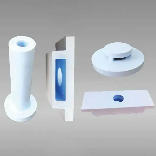
Flow pipes and float plates are complementary components used in launders, troughs, transfer lines and pour spouts to control molten-metal motion and surface behavior before degassing, filtration and mold filling. The flow pipe is the channel or nozzle that delivers metal into a launder, trough or receiver. The float plate is a passive or guided refractory plate that sits at or near the melt surface to moderate jet impact, trap floating dross and stabilize surface flow. Together they form a low-cost, high-impact subsystem for any aluminum casting line focusing on cleanliness and repeatable filling.
Why these components matter for casting quality
-
They reduce local jet velocities that otherwise erode filters and re-entrain oxides.
-
They produce calmer surface conditions so buoyant dross can rise and be skimmed more efficiently.
-
They permit narrower pour height windows by stabilizing flow, which benefits thin-wall and precision castings.
-
They help protect downstream degassing units by moderating inflow conditions.
These benefits combine to reduce scrap, cut machining rework and extend the service life of consumables such as filters and rotor heads.
Flow Pipe Float Plate Specification:
| items | Dimensions | Special dimensions | Package | Special package |
| Flow pipe | 100-650mm | As drawing | 50pieces/box | As required |
Core ADtech design features and benefits
-
High-silicon refractory lining on flow pipes provides anti-wetting, chemical stability and low adhesion.
-
Optimized nozzle geometry (taper, lip and chamfer profiles) to minimize splash and reduce erosion.
-
Float plate variants: floating skirt plate, sealed floating plate, and guided slotted plate for different shop needs.
-
Anti-wetting coatings available, including boron nitride based treatments for very clean alloy work.
-
Modular mounting to permit quick removal for inspection or replacement without a full launder shutdown.
-
Optional instrumentation: thermocouple ports and level-sensing cutouts to monitor surface behavior and temperature.
How the flow pipe works, hydraulic and metallurgical principles
The flow pipe controls the velocity profile and jet breakup as molten metal leaves a ladle, launder or spout. Key elements that determine performance are discharge diameter, lip geometry, wettability of the nozzle face and the relative pour height. Controlled outflow minimizes vortexing and reduces gas entrainment. A correctly profiled flow pipe forms a coherent, low-spray jet which, when combined with a float plate, transitions to a gentle surface flow that preserves melt cleanliness.
How the float plate works, surface stabilization and dross handling
Float plates act at the air-metal interface. Typical mechanisms:
-
They intercept the jet or incoming stream to spread and diffuse energy horizontally.
-
A floating or semi-floating plate forms a calm pool downstream where light oxides rise and collect.
-
Slotted or notched float plates can meter discharge and maintain a steady head to protect filters.
Float plates may be free-floating (resting on the melt surface), supported at edges, or guided within a mounting frame. Choice depends on process access, cleanliness targets and maintenance constraints.
Typical configurations and selection guide
Table 1: Common component styles and applications
| Component | Style | Typical application |
|---|---|---|
| Flow pipe | Short tapered nozzle | Direct ladle-to-launder feed for small pours |
| Flow pipe | Long spout with lip chamfer | High pour heights, minimize splash |
| Float plate | Free-floating circular plate | Quick retention of dross, simple maintenance |
| Float plate | Guided slotted plate | Precise metering into filters or troughs |
| Combined assembly | Pipe with integrated plate guard | Maximum protection for filter faces |
Selection must be guided by pour mass, pour height, alloy, and downstream equipment geometry.
Materials, coatings and manufacturing notes
-
Hot-face materials: high-silicon castables, dense alumina, and SiC-reinforced castings are common. Each offers a trade-off between cost, thermal shock tolerance and erosion resistance.
-
Coatings: boron nitride and non-wetting proprietary coatings reduce metal adhesion and lower dross accumulation on the component face. Coatings require periodic re-application depending on duty.
-
Manufacturing tolerances: concentricity and lip finish matter; poorly finished lips increase turbulence and erosion. Precision machining and controlled firing improve life.
Installation and preheat recommendations
-
Preheat components gradually to specified temperatures to remove moisture and avoid thermal shock (typical ramp depends on mass and material).
-
Mount flow pipes using precision seats and high-temperature gaskets to prevent bypass.
-
Install float plates with their intended freedom of movement and ensure skimming access near the settling pocket.
-
Record initial pour curves and set baseline head loss and temperature metrics. These serve as reference during commissioning.
Maintenance and lifecycle management
Table 2: Recommended maintenance schedule
| Interval | Task |
|---|---|
| Daily | Visual check of plate movement and pipe lip condition; confirm thermocouples |
| Weekly | Inspect seats, clamps and coating condition; clear accumulated dross |
| Monthly | Measure lip wear and plate thickness; reapply coating if needed |
| Quarterly | Replace gaskets and inspect refractory bond; log wear rates |
| Annual | Full removal, inspection and reline if erosion exceeds threshold |
Keep spare float plates and one spare flow pipe per critical station for rapid replacement.
Troubleshooting matrix
Table 3: Symptoms, causes and corrective actions
| Symptom | Possible cause | Action |
|---|---|---|
| Excess splashing downstream | Incorrect nozzle lip profile or too high pour height | Reduce pour height, check lip finish, adjust nozzle geometry |
| Frequent filter clogging | Jet impingement on filter face | Add or reposition float plate, insert flow spreader |
| Float plate sticking | Heavy dross, coating failure, or warped plate | Replace plate, clean skimming ports, recoat plate |
| Rapid nozzle erosion | Abrasive inclusions or high local velocity | Add upstream skimming, review degassing, change to SiC-enriched nozzle |
| Intermittent flow | Bypass around pipe seat or gasket failure | Replace gasket, reseat pipe, torque clamps evenly |
Document each event with pour parameters to find root cause patterns.
Integration with degassing, filtration and pour systems
Best practice melt-train sequence to protect downstream assets:
-
Ladle/furnace discharge through flow pipe.
-
Float plate creates calm pocket and allows skimming.
-
Degasser (rotor or vacuum) treats dissolved hydrogen.
-
Filtration unit (foam, plate, cartridge) polishes inclusions before mold fill.
Proper spatial arrangement and timing reduce filter load and increase component life.
Performance metrics and verification
Measure component impact using:
-
Reduced Pressure Test (RPT) before and after installation.
-
Inclusion counts and size distribution from sectioned castings.
-
Head loss and pour rate logs to assess hydraulic resistance.
-
Visual scoring of surface finish and machining scrap rates.
Use SPC charts to monitor trends and trigger preventive maintenance.
Economic rationale and ROI modeling
Value drivers include extended filter life, lower scrap, reduced finishing labor and fewer emergency stoppages.
Table 4: Illustrative ROI example
| Metric | Example value |
|---|---|
| Annual throughput | 2,500 tonnes |
| Reduction in filter replacements | 20% |
| Scrap reduction from surface defects | 0.7% absolute |
| Annual metal saved | 17.5 tonnes |
| Annual estimated savings | Site dependent; often USD tens of thousands |
| Typical payback | 6 to 18 months depending on baseline |
Run a pilot to gather plant-specific numbers for accurate ROI.
Safety, environmental and regulatory considerations
-
Preheat to remove moisture and avoid steam incidents.
-
Manage skimmed dross per local environmental regulations; many skimmings contain recoverable aluminum.
-
Use fume extraction during skimming and when components are exposed.
-
Ensure operators use full molten-metal PPE and follow lock-out procedures for any moving float plate assemblies.
Design examples and technical specification checklist
Table 5: Example technical specs
| Parameter | Typical range / option |
|---|---|
| Flow pipe inner diameter | 25 mm to 150 mm (custom available) |
| Flow pipe material | High-silicon castable, dense alumina, SiC-reinforced options |
| Float plate diameter | 150 mm to 800 mm, custom shapes |
| Plate thickness | 10 mm to 50 mm depending on style |
| Operating temperature | 650°C to 800°C |
| Coating options | Boron nitride, proprietary anti-wetting coatings |
| Mounting | Flanged seat, clamp plate or mortise-style pocket |
| Preheat method | Electric jackets, induction blankets, oven bake |
Float plate styles and selection guidance
-
Free-floating disc: simple, low-cost, easy to replace. Best for small pours and pilot lines.
-
Guided slotted plate: maintains a calibrated gap and provides predictable head control for automatic lines.
-
Perforated spreader plate: when slow spread and distributed flow is required to protect sensitive filters.
-
Skimmer-integrated plate: incorporates notches or hooks to guide skimming and speed removal of surface scum.
Choose style based on pour cadence, access for skimming and required metering precision.