Ceramic foam filters installed and preheated correctly remove sub-micron and micron-scale inclusions, control flow patterns into molds, and measurably lower casting defects and scrap for high-purity and precision aluminum work; when matched to alloy, pore structure and filter thickness, foam filters deliver predictable improvement in surface quality, mechanical uniformity and first-pass yield, making them a cost-effective core component of any modern aluminum casting line.
Why ceramic foam filters matter to aluminum foundries
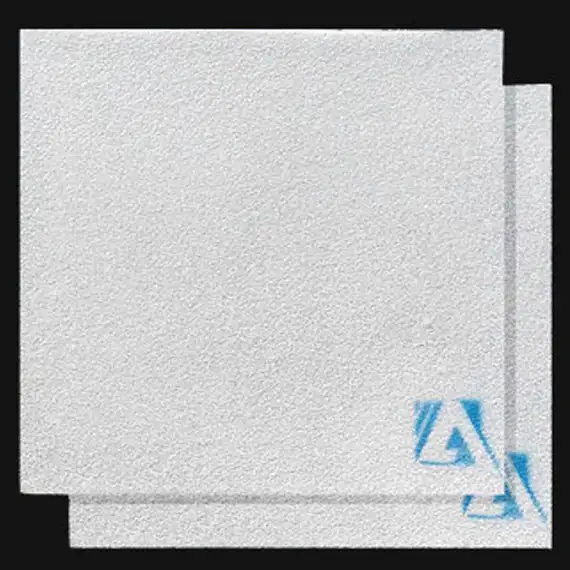
Molten aluminum commonly carries oxide films, entrained dross fragments, sand, and other particles that act as stress concentrators or surface blemishes after solidification. Ceramic foam filters remove these contaminants while simultaneously smoothing flow into the mold so that turbulence and re-entrainment are minimised. For precision components and structural castings, filtration reduces downstream machining scrap, improves fatigue life and raises first-pass yield. Ceramic foam media provide a balance of high porosity and internal surface area that achieves effective capture without excessive head loss.

Consult Our Engineers for Your Casting Process
Materials and chemistry: alumina, silicon carbide and zirconia options
Ceramic foam filters are manufactured from different refractory chemistries to match alloy requirements and operating temperatures.
-
Alumina (Al2O3) foam is the most common choice for aluminum casting due to chemical compatibility, cost efficiency and adequate thermal resistance for aluminum process windows.
-
Silicon carbide reinforced foams provide improved thermal shock resistance and mechanical strength where higher abrasion or thermal cycling is expected.
-
Zirconia based foams offer the highest refractoriness and chemical stability and are used in specialty applications or where extreme thermal stability is needed. Their operating temperatures and strength ratings exceed typical aluminum needs but they command a premium.
Selecting chemistry depends on the alloy mix, flux practice and whether the work involves repeated heating cycles that stress filter integrity.
Pore size, porosity and how PPI influences performance
Pore density expressed as PPI pores per inch is the primary variable process engineers use to tune filtration.
-
Low PPI (8 to 20 PPI) provides high permeability, low head loss and is suited for heavy inclusions and high-flow pours.
-
Mid PPI (20 to 30 ppi) is a common starting point for general aluminum castings.
-
High PPI (30 to 60) targets smaller inclusions and finer cosmetic requirements but increases head loss and the risk of earlier clogging if melt cleanliness is poor.
Porosity in ceramic foam is typically high, often 80 to 90 percent, which gives a deep bed capture mechanism where particles are trapped through a combination of interception, inertial impaction and adhesion to the porous strut surfaces. Hydraulic characterization and recent studies support the principle that pore structure controls both capture efficiency and flow pressure drop.
Request a Competitive Factory Quote for Alumina Ceramic Foam Filters
Standard sizes for Ceramic Foam Filters:
Dimension (± 3 mm ):
7x7in 9x9in 12x12in 15x15in 17x17in 20x20in 23x23in 26x26in
Thickness:
50 ± 2 mm
Bevel Angle:
17.5± 1.5°
Special Dimension:
square, rectangular, round, trapezoidal, abnormal, or customized as per the requirement.
Technical Parameters:
| Item | Density (g/cm³) |
Rupture Modulus (816℃ /Mpa) |
Comprehensive Strength (Mpa) |
Operating Temperature (℃) |
Sealing gasket expanding temperature (℃) |
| Index | 0.45 | 5.5 | 0.8-1.0 | 1350 | 450-550 |
Pore size for Ceramic Foam Filter:
Pores amount in any 25.4mm length filter:
| Mesh Number(PPI) | 10 | 20 | 30 | 40 | 50 | 60 |
|---|---|---|---|---|---|---|
| Pore Density(PCS) | 8-12 | 18-22 | 28-32 | 38-42 | 48-52 | 58-62 |
The distribution curve of pore size:
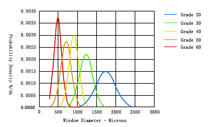
Filtration Precision for Ceramic Foam
| Pore Size(PPI) | 20 | 30 | 40 | 50 | 60 |
|---|---|---|---|---|---|
| Inclusions Diameter(um) | 80 | 40 | 20 | 10 | 5 |
| Filtration Rate(%) | 78 | 85 | 88 | 92 | 95 |
Application Data for Ceramic Foam Filters
| Specifications (mm) | Effective filtration area(%) | Filtration flow range(kg/min) |
|---|---|---|
| 7in(178*178*50) | 75 | 22-56 |
| 9in(229*229*50) | 75 | 25-80 |
| 12in(305*305*50) | 80 | 50-156 |
| 15in(381*381*50) | 85 | 85-252 |
| 17in(432*432*50) | 86 | 110-335 |
| 20in(508*508*50) | 88 | 160-478 |
| 23in(584*584*50) | 89 | 210-640 |
| 26in(660*660*50) | 90 | 276-830 |
Packing Specification for Ceramic Foam Filter Standard pallet, quantified packaging, and approximate weight
| Standard Pallet, Quantitative Packaging and Weight | |||||
| Filter Dimention (mm) |
Filter QTY per Case (Pcs) |
Case QTY per Pallet (Case) |
QTY per Pallet (Pcs) |
Pallet Dimension (mm) |
Pallet General Weight (Kg) |
|---|---|---|---|---|---|
| 660x660x50(26″) | 4 | 8 | 48 | 1100*1100*2200 | 490 |
| 584x584x50(23″) | 5 | 12 | 60 | 950*950*2050 | 510 |
| 508x508x50(20″) | 5 | 18 | 90 | 1100*900*1720 | 470 |
| 432x432x50(17″) | 5 | 24 | 120 | 1100*1100*1670 | 450 |
| 381x381x50(15″) | 5 | 24 | 120 | 1100*1100*1540 | 430 |
| 305x305x50(12″) | 10 | 16 | 160 | 1000*1000*1550 | 350 |
| 228x228x50(9″) | 10 | 20 | 200 | 1100*1100*1400 | 310 |
| 178x178x50(7″) | 10 | 20 | 200 | 1100*1100*1400 | 220 |
Check Stock Availability and Ceramic Foam Filter Price
How filtration works in practice: deep bed capture and flow conditioning
Ceramic foam filters operate as deep bed filters rather than simple sieves. Incoming molten metal passes through the three-dimensional network of interconnected pores. Fine particles and oxides adhere to strut surfaces, agglomerate and are retained within the depth of the filter. The porous network also converts turbulent flow into a more laminar profile, significantly reducing splashing and vortex formation at the mold inlet. Because of this, properly sized foam filters lower entrained gas and decrease pinholes and other porosity types linked to flow disturbances.

Matching filter geometry to casting parameters
Choosing filter thickness, PPI and mounting orientation must consider pour mass, gating geometry and riser heights.
Table 1 Typical matching guidelines
| Casting parameter | Suggested starting filter choice | Rationale |
|---|---|---|
| Large ingots, high mass pours | 10 to 20 PPI, thicker filter 50–75 mm | High permeability reduces head loss in heavy flows |
| General automotive parts | 20 to 30 PPI, 25–50 mm thickness | Balance of capture and flow for mixed inclusions |
| Precision housing, visible surfaces | 30 to 60 PPI, 25–50 mm thickness | Higher capture of small inclusions, smoother surface finish |
| Thin wall, low pour height | Lower PPI with careful gating design | Maintain flow rate while avoiding filter damage |
These settings are starting points. Validate with Reduced Pressure Test and inclusion counts on sectioned parts.
Installation best practices and preheat procedure
Proper installation and preheating are decisive for filter lifetime and performance.
-
Preheat the filter to molten metal temperature or to a controlled preheat temperature to remove residual moisture and minimise thermal shock. Typical preheat periods vary but 15 to 30 minutes are common for many shop practices. Preheating prevents steam explosions and helps the filter seat correctly.
-
Orientation matters. Follow the arrow marks on filters when present. Ensure filter faces are aligned with the intended flow direction and that seals prevent bypass around the edges.
-
Gasket and sealing. Use high temperature gaskets or refractory seals that compress to prevent metal bypass. Inspect seals regularly and replace when deformation or erosion is observed.
-
Protect from direct jet impingement. If pouring from a ladle or funnel with a concentrated jet pattern, use flow spreaders or staggered placement so the melt does not strike the filter face directly at high velocity which can fracture the foam.
Follow shop safety protocols when preheating and avoid rapid temperature changes that could crack the ceramic matrix.

Filter life, clogging and replacement indicators
Filter life depends on inclusion load, PPI, thickness and pour profile. Common indicators to change filters include:
-
Rising head loss measured as reduced pour rate at the same pour height.
-
Reduced pouring time or irregular flow during normal production cycles.
-
Visible blowouts or filter cracking noted during post-pour inspection.
-
Inclusion breakthrough seen in sectioned castings despite filter presence.
Keeping records of filter life versus production variables helps establish optimal change intervals and stocking levels for spares.
Request a Tailored Filtration Solution
Integration with ADtech plate boxes and ladle systems
Ceramic foam filters pair with ADtech plate-type or box filters to create a controlled filtration system. The box ensures proper seating and seal, while the foam media provides the particle capture and flow conditioning. For automated or continuous lines, the filter assembly can include hydraulic or motorized clamping and a fast-change cassette for minimal downtime.
Design the box so the filter sits immediately upstream of the pour nozzle to avoid recontamination and maintain laminar filling into the mold cavity.
Performance verification and measurement techniques
Validate filter performance using a combination of:
-
Reduced Pressure Test (RPT) to compare porosity before and after filtration. Collect baseline and post-installation data for SPC control.
-
Inclusion analysis on sectioned parts or metallographic samples to quantify inclusion counts and size distribution.
-
Hydraulic monitoring by logging pour rates and head loss across filter batches to detect clogging trends. Recent hydraulic studies provide models to predict pressure drop for given PPI and flow conditions.
Use these methods together to demonstrate the ROI of filtration investments and to tune PPI and thickness for peak performance.
Safety, environmental and handling guidance
-
Handling. Store ceramic filters in dry, controlled environments to prevent moisture pickup. Preheat in controlled ovens or with specified heater systems to avoid steam hazards.
-
Spent media and dross. Collect and manage spent filters and trapped dross as per local waste and recycling regulations. Many spent filters contain recoverable aluminum and can enter metal recovery streams after safe handling.
-
Operator PPE. Use heat resistant gloves, face shields, aprons and follow molten metal handling procedures. Ensure fume extraction for any fluxing or skimming activity near the filter station.
Comparison with alternate filtration solutions
Table 2 Comparative summary
| Metric | Ceramic foam filter | Fiber filters | Tubular filters |
|---|---|---|---|
| Capture of sub-micron particles | High | Moderate | Moderate |
| Flow conditioning (laminarisation) | Excellent | Good | Variable |
| Thermal shock tolerance | Good to excellent (chemistry dependent) | Lower | Varies |
| Cost per filter | Moderate | Low | Can be higher for special ceramics |
| Ease of installation | Medium | Easy | Medium |
| Reusability | No, consumable | Some designs disposable | Some designs consumable or replaceable |
Ceramic foam filters are often the preferred option for high-precision castings because of their combined capture depth and flow conditioning properties.
Economic case and sample ROI
Filtration reduces scrap and downstream rework. Typical savings arise from fewer surface repairs, lower machining scrap and higher acceptance rates.
Table 3 Illustrative ROI calculation
| Parameter | Example input | Notes |
|---|---|---|
| Annual melt throughput | 2,500 t | |
| Pre-filter scrap rate | 1.8% | Due to surface inclusions and porosity |
| Post-filter scrap rate | 0.7% | After filter and process tuning |
| Metal saved annually | 27.5 t | (1.1% of 2500 t) |
| Value per tonne aluminum | $1,800 | Market dependent |
| Annual metal value saved | $49,500 | Excludes machining and labor savings |
| Estimated annual consumable and filter cost | $12,000 | Filters, gaskets, handling |
| Net annual benefit | $37,500 | Rough example; site data required for accuracy |
| Payback | Months | Typically under 12 to 24 months for medium foundries |
Site trials and accurate cost inputs for scrap, rework and machining are essential for a reliable payback estimate.
Troubleshooting common issues and corrective actions
Table 4 Troubleshooting matrix
| Symptom | Likely cause | Corrective action |
|---|---|---|
| Filter cracking during pour | Filter not preheated or thermal shock | Increase preheat time, check heater uniformity |
| Rapid clogging | High inclusion load or wrong PPI | Use coarser PPI or upstream skimming/degassing |
| Bypass around edges | Poor seal or gasket failure | Replace gasket, confirm seating and clamp pressure |
| Reduced surface quality post-install | Incorrect PPI or filter orientation | Check arrow direction, run inclusion analysis and adjust PPI |
| Short filter life | Excessive flux residues or aggressive alloy | Evaluate chemistry, consider more erosion resistant foam |
Document each event and corrective action to build a troubleshooting knowledge base for operators.
Standards, tests and validation methods
Foundries should adopt routine measurements to control filtration results:
-
Baseline RPT and periodic RPT after filter changes.
-
Inclusion microscopy and size distribution for critical parts.
-
SPC control charts for pour rate, head loss and scrap rate to monitor filter performance over time.
-
Supplier performance data including recommended PPI ranges and recommended preheat cycles.
Using formal acceptance criteria for each alloy and casting family helps maintain consistent quality.
Product specification examples
Table 5 Representative ceramic foam filter catalog
| Model | Composition | PPI range | Thickness mm | Typical application |
|---|---|---|---|---|
| CFF-Al20 | High purity alumina | 10, 20, 30 | 25 / 50 / 75 | General purpose aluminum casting |
| CFF-SiC30 | SiC reinforced alumina | 20, 30 | 25 / 50 | Abrasive or rapid cycling lines |
| CFF-ZR45 | Zirconia enriched | 30, 45, 60 | 25 / 50 | Specialty high temp or corrosive melts |
Custom sizes and shapes available for ADtech plate boxes and cup systems.
Get Quote for Alumina Ceramic Foam Filters Now
FAQs
What PPI should I start with for general aluminum casting?
Why must ceramic filters be preheated?
Can ceramic foam filters handle repeated thermal cycles?
How do I detect filter bypass?
Are ceramic foam filters recyclable?
How often must I change filters?
Can filters remove dissolved hydrogen?
What causes early filter clogging?
Do filter pore size and thickness affect pouring height limits?
How should I validate a supplier claim about filter performance?
Case
A mid-size die cast supplier introduced 30 PPI alumina foam filters into a production cell with chronic surface blowholes. After matching filter area and preheat procedures, their RPT scores improved and surface defect rejections fell by over 50 percent in three months. Consumable costs rose modestly but were offset by reduced rework and faster finishing operations.