

An industrial aluminum liquid filter box is a refractory-lined housing unit installed within the metal delivery path of a casting line, designed to hold ceramic foam, tubular, or plate filters in a fixed position so molten aluminum passes through the filtration media before reaching the mold or casting machine. The filter box itself doesn’t filter anything directly, its job is to position, seal, and protect the actual filter element while maintaining consistent flow geometry and preventing unfiltered metal from bypassing around the filtration media. We have installed and serviced these units across several aluminum casting operations, and the recurring lesson we keep learning is that foundries often invest heavily in premium filter media while treating the filter box housing itself as an afterthought, which undermines the entire filtration investment when the housing doesn’t seal or position the filter correctly.
If your project requires the use of Aluminum Liquid Filter Box, you can contact us for a free quote.
What an Aluminum Liquid Filter Box Actually Is
A filter box, sometimes called a filter housing, filter chamber, or filter print depending on regional terminology and the specific casting process involved, serves as the structural framework that holds a ceramic filter element in the correct position within the molten metal flow path. Picture it as a specialized container built to withstand direct contact with liquid aluminum at temperatures typically between 680°C and 750°C, engineered with an internal cavity precisely shaped to accept a specific filter type and size while directing incoming metal flow through the filter media rather than around it.
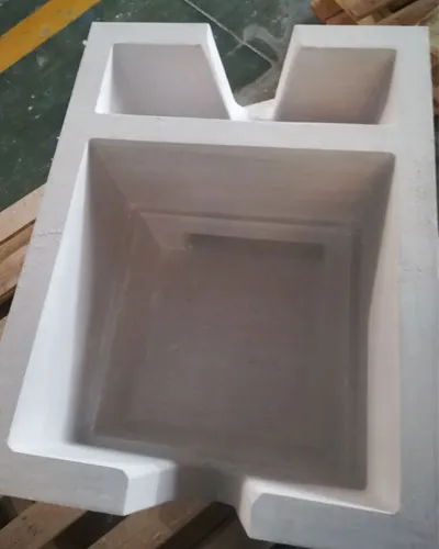
The box typically integrates directly into the launder system, the trough network that carries molten aluminum from the holding furnace toward the casting machine or mold. Metal flows into one side of the box, encounters the seated filter element, passes through the filtration media, and exits the opposite side continuing toward its casting destination. This sounds straightforward, but the engineering behind making this happen reliably, batch after batch, without leakage or bypass, involves more careful design than most people outside the foundry equipment world realize.
We often explain the filter box’s role to newer procurement staff using a simple analogy: if the ceramic filter is the coffee filter itself, the filter box is the coffee maker’s filter basket, the housing that holds everything in place and makes sure water, or in this case molten metal, actually passes through the filter paper rather than spilling around its edges. A brilliant filter paper does nothing useful in a poorly designed or damaged basket.
| Filter Box Component | Function |
|---|---|
| Outer structural shell | Provides mechanical support and containment |
| Refractory lining | Protects structure from direct molten metal contact |
| Filter seating cavity | Holds filter element in precise position |
| Inlet and outlet channels | Directs flow into and out of the filtration zone |
| Sealing interface | Prevents metal bypass around filter edges |
| Access point/lid | Allows filter insertion and removal |
Why the Filter Box Matters as Much as the Filter Itself
We’ve encountered numerous foundries that invested significant budget upgrading to premium ceramic foam or tubular filters while running those filters inside worn, poorly sealed, or dimensionally mismatched filter boxes, essentially undermining the entire investment before the metal even reaches the filtration media.
A filter box with a degraded sealing surface allows molten aluminum to flow around the filter edges rather than through the filtration material, meaning a portion of the total metal volume passes completely unfiltered even while the filter itself might be functioning perfectly for the metal that does pass through it correctly. This bypass problem is particularly insidious because it doesn’t cause total filtration failure, quality still improves somewhat compared to no filtration at all, but the improvement falls well short of what the filter media is actually capable of delivering, and operators often don’t realize how much performance they’re leaving on the table.
Dimensional mismatch between the filter box cavity and the actual filter element creates similar problems, either preventing proper seating that leads to bypass, or in the opposite case, creating stress on the filter element during installation that can cause cracking, particularly with brittle ceramic materials that don’t tolerate forced fitting well.
| Filter Box Condition | Effect on Filtration Performance |
|---|---|
| Properly sealed, correctly sized | Full filtration performance as designed |
| Degraded seal, minor gap | Partial bypass, reduced effective filtration |
| Significant seal failure | Major bypass, filtration largely ineffective |
| Dimensional mismatch (too large) | Bypass around loosely fitted filter |
| Dimensional mismatch (too small) | Installation stress, filter cracking risk |
We measured this bypass effect directly at one facility using inclusion count testing on metal samples taken immediately downstream of a filter box with visible sealing gasket degradation, compared against samples from an identical filter box with fresh sealing material. The difference in captured inclusion count was substantial enough that the plant immediately added gasket inspection to their standard changeover checklist going forward.
Construction Materials and Refractory Lining
Filter box construction typically involves an outer structural shell, usually steel, paired with an internal refractory lining that provides the actual barrier against molten aluminum contact and the associated thermal and chemical stresses.
The outer shell provides mechanical rigidity and structural support, holding the overall shape and withstanding the physical forces involved in positioning within the casting line, including the weight of the metal flowing through and any mechanical stress from the surrounding launder support structure.
The refractory lining does the actual work of surviving direct contact with molten aluminum, and lining material selection significantly affects both the filter box’s service life and its resistance to metal penetration or chemical attack over repeated thermal cycling. Common lining materials include castable refractory concrete formulated specifically for aluminum contact, precast refractory shapes fitted into the steel shell, and in some higher-performance applications, ceramic fiber board or composite linings offering better thermal shock resistance for operations with frequent startup and shutdown cycles.
| Lining Material | Thermal Shock Resistance | Typical Service Life | Best Application |
|---|---|---|---|
| Standard castable refractory | Moderate | Moderate | General purpose, steady continuous operation |
| Precast refractory shapes | Good | Extended | High-volume operations, less frequent cycling |
| Ceramic fiber composite | Excellent | Varies, good for cycling | Frequent startup/shutdown operations |
| Low-cement castable | Good | Extended | Applications needing reduced porosity |
We tend to recommend foundries running highly variable production schedules with frequent furnace shutdowns invest in ceramic fiber composite lined filter boxes despite the higher upfront cost, since standard castable refractory linings tend to develop thermal cracking faster under repeated heating and cooling cycles compared to more thermally tolerant alternatives.
Types of Filter Boxes for Different Casting Applications
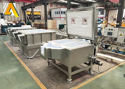
Different casting processes call for different filter box configurations, and understanding these variations helps buyers specify the correct equipment for their specific production setup.
Single filter print boxes accommodate one flat ceramic foam filter, positioned within a launder or gating system, common in sand casting and general DC casting applications where a single filtration point adequately serves the production flow rate.
Dual or multi-cavity filter boxes allow simultaneous use of multiple filter elements, either running in parallel to increase total flow capacity or in series to combine different filtration stages, useful for high-volume continuous casting lines where single filter capacity would create a bottleneck.
Tubular cartridge filter housings are specifically engineered to accommodate the cylindrical geometry of tubular ceramic filters rather than flat plate designs, requiring different internal cavity shaping and sealing approaches compared to flat filter boxes.
Integrated launder filter boxes are built directly into the launder system as a continuous section rather than as a separate removable unit, common in permanent continuous casting installations where the filtration point doesn’t need frequent relocation.
Portable/removable filter boxes allow easier access for filter changes and cleaning, often preferred in operations running multiple alloy changes or shorter production campaigns where flexibility matters more than permanent integration.
| Filter Box Type | Filter Media Accommodated | Typical Application |
|---|---|---|
| Single print box | Flat ceramic foam filter | General sand and DC casting |
| Multi-cavity box | Multiple flat filters, parallel or series | High-volume continuous casting |
| Tubular cartridge housing | Cylindrical tubular filters | High-throughput, extended service applications |
| Integrated launder section | Various, built into permanent line | Fixed continuous casting installations |
| Portable/removable unit | Various, designed for easy access | Multi-alloy, shorter campaign operations |
Filter Box Design and Flow Geometry
The internal shape of a filter box affects flow behavior before, through, and after the filter element in ways that directly influence overall filtration effectiveness, and this is a design element we find gets far less attention than filter media selection despite being equally important.
Inlet chamber geometry needs to distribute incoming flow evenly across the entire filter face rather than concentrating it toward one area, since concentrated flow creates localized high-velocity zones that can push larger inclusions through the filter media at that specific point while other areas of the filter remain underutilized. A well-designed inlet chamber includes some form of flow distribution feature, whether a baffle, a gradually widening chamber shape, or a diffuser section, that spreads incoming metal across the full filter width before it makes contact with the filtration media.
Outlet chamber design matters for similar reasons, ensuring filtered metal exits smoothly without creating backpressure that could force flow imbalances back through the filter itself. Poor outlet geometry can create turbulence immediately downstream of the filter that, in worst cases, actually disturbs the filter’s outlet face and dislodges some previously captured material.
Chamber volume relative to flow rate affects residence time and how the system responds to flow rate changes during production, with excessively small chambers creating more turbulent, harder to control flow conditions compared to appropriately sized chambers that allow smoother transitions.
| Flow Geometry Feature | Purpose | Consequence if Poorly Designed |
|---|---|---|
| Inlet distribution chamber | Spreads flow evenly across filter face | Localized high-velocity bypass zones |
| Outlet chamber design | Smooth exit without backpressure | Turbulence disturbing filter outlet face |
| Chamber volume sizing | Appropriate residence time | Excessive turbulence, unstable flow |
| Transition angles | Gradual flow direction changes | Turbulence, uneven filter loading |
Sealing Systems and Preventing Metal Bypass
Sealing represents perhaps the single most critical functional aspect of filter box design, since even the finest filtration media accomplishes nothing if a meaningful portion of metal flow finds a path around rather than through it.
Gasket materials used in filter box sealing applications need to withstand the operating temperature while maintaining enough compliance to conform to minor surface irregularities on both the filter element and the housing cavity. Ceramic fiber gasket material remains the most common choice, offering reasonable compressibility at installation combined with adequate temperature resistance for continued service.
Mechanical clamping or wedging systems that physically press the filter into firm contact with the sealing surface matter as much as the gasket material itself, since even a good gasket material fails to seal properly without adequate, evenly distributed clamping pressure holding everything in firm contact throughout the production run.
Some advanced filter box designs incorporate self-sealing features where the natural pressure of the metal head itself helps press the filter more firmly into its seat as flow begins, though this approach requires careful engineering to ensure it works as intended rather than creating inconsistent sealing that varies with flow conditions.
| Sealing System Element | Function | Common Failure Mode |
|---|---|---|
| Ceramic fiber gasket | Conforms to surface irregularities | Degradation from repeated thermal cycling |
| Mechanical clamping mechanism | Maintains consistent contact pressure | Loosening over time, uneven pressure distribution |
| Cavity surface condition | Provides consistent sealing contact point | Erosion or damage creating gaps |
| Filter dimensional consistency | Ensures proper fit against sealing surface | Batch variation causing inconsistent seating |
We recommend foundries inspect gasket condition at every filter change rather than assuming reusability across multiple cycles, since the cost of gasket material is minor compared to the quality consequences of running with a compromised seal, and gaskets exposed to repeated thermal cycling degrade in ways that aren’t always immediately visible during quick visual inspection.
Filter Box Sizing and Capacity Considerations
Matching filter box size and capacity to actual production flow requirements prevents both underutilization of oversized equipment and the bottlenecking that comes from undersized filtration relative to pour rate.
Flow capacity calculations need to account for peak flow rate during pouring, not just average flow rate across a production cycle, since undersizing based on average figures can create problems during peak flow moments even if the average throughput seems adequately matched to the filter box specification.
| Production Scale | Typical Filter Box Consideration |
|---|---|
| Small batch sand casting | Single small filter print box, simple design adequate |
| Medium volume DC casting | Standard single or dual cavity box matched to mold width |
| High-volume continuous casting | Multi-cavity or tubular cartridge housing for extended capacity |
| Multi-strand casting operations | Distribution system feeding multiple filter boxes or single large-capacity unit |
We advise buyers to request flow capacity data specific to aluminum from their filter box supplier rather than assuming generic industrial filtration housing specifications translate directly, since aluminum’s specific density and flow characteristics at casting temperature don’t always match assumptions built into filtration equipment designed originally for other industries or metals.
Installation Within the Casting Line
Filter box placement within the overall casting line layout affects both filtration effectiveness and practical operational considerations like accessibility for filter changes and maintenance.

Positioning too close to the holding furnace outlet can expose the filter box to more turbulent flow conditions before the metal stream has stabilized, while positioning too close to the mold or casting point reduces the available residence time for any settling or stabilization benefit that occurs naturally within the launder system.
Accessibility for filter changes matters practically, since a filter box positioned in a location requiring extensive line shutdown or difficult manual access for routine filter replacement adds unnecessary labor time and production disruption to what should be a relatively routine maintenance task.
Height and gravity flow considerations affect filter box placement in gravity-fed systems, since the filter box needs positioning that maintains adequate head pressure to drive metal through the filtration media at the required flow rate without creating excessive pressure that risks filter damage.
| Installation Consideration | Design Implication |
|---|---|
| Distance from furnace outlet | Balance turbulence stabilization against unnecessary heat loss |
| Distance from mold/casting point | Ensure adequate residence time without excessive cooling |
| Accessibility for maintenance | Position for reasonable filter change access without major shutdown |
| Height relative to flow source | Maintain appropriate head pressure for gravity-fed systems |
Preheating Requirements and Thermal Management
Filter boxes, like the ceramic filters they house, require proper preheating before molten metal contact to prevent thermal shock damage to both the refractory lining and any filter element already positioned within the housing.
Cold filter boxes brought directly into contact with molten aluminum risk cracking the refractory lining, and this damage isn’t always immediately obvious, sometimes manifesting as gradual metal penetration into developing cracks over subsequent production cycles rather than immediate catastrophic failure. This delayed failure pattern makes proper preheating discipline important even when operators don’t see immediate consequences from skipping the procedure.
Preheating duration and target temperature depend on the specific refractory lining material and filter box size, with larger units generally requiring longer preheat cycles to achieve uniform temperature throughout the lining thickness rather than just surface heating that leaves cooler material underneath still vulnerable to thermal shock.
| Preheating Factor | Consideration |
|---|---|
| Target preheat temperature | Match to refractory material specification |
| Preheat duration | Scale with filter box size and lining thickness |
| Heating method | Gas torch, electric preheat oven, or gradual furnace proximity heating |
| Temperature verification | Use appropriate pyrometer rather than visual estimation |
Benefits of Properly Designed Filter Box Systems
Foundries that invest in properly engineered and well-maintained filter box systems see benefits extending beyond the immediate filtration performance improvement.
Consistent filtration performance: Proper sealing and flow geometry ensure the filter media performs at its designed capability rather than underperforming due to bypass or turbulence issues.
Extended filter service life: Well-designed flow distribution reduces localized stress and premature clogging that can occur when flow concentrates unevenly across a filter face.
Reduced changeover time: Filter boxes designed with practical accessibility in mind reduce the labor time required for routine filter replacement, improving overall line efficiency.
Lower risk of production interruption: Reliable sealing and structural integrity reduce the risk of unexpected metal leakage or filter box failure during production, which can cause significant downtime and safety concerns if it occurs.
Better return on filter media investment: Since filter box performance directly affects how much of the metal flow actually passes through filtration media, a well-functioning housing ensures foundries get full value from whatever filter media quality level they’ve chosen.
| Benefit Category | Practical Impact |
|---|---|
| Filtration consistency | Full utilization of filter media capability |
| Filter service life | Extended time between changes |
| Changeover efficiency | Reduced labor time per filter change |
| Production reliability | Lower risk of unexpected downtime |
| Investment return | Better value from filter media expenditure |
Common Problems and Failure Points
Certain recurring issues show up across filter box installations regardless of foundry size or casting process, and recognizing these patterns speeds up problem diagnosis.
Refractory lining cracking, often from inadequate preheating or repeated thermal cycling beyond the material’s tolerance, gradually allows metal penetration that can eventually compromise the structural integrity of the entire housing if left unaddressed.
Gasket degradation leading to bypass, as discussed earlier, remains one of the most common yet under-inspected failure points, particularly in operations that don’t build gasket condition checks into their standard maintenance routine.
Erosion at high-flow contact points within the housing, particularly at inlet transition areas where flow velocity concentrates, can gradually alter the internal geometry in ways that affect flow distribution across the filter face over the housing’s service life.
Structural distortion of the outer steel shell from repeated thermal cycling can eventually affect the internal cavity dimensions enough to create fitting problems with filter elements that previously seated correctly, an issue that develops gradually enough to escape notice until fitting problems become obvious.
| Problem | Root Cause | Detection Method |
|---|---|---|
| Refractory lining cracking | Inadequate preheating, thermal cycling fatigue | Visual inspection during filter changes |
| Gasket-related bypass | Seal degradation, inconsistent clamping pressure | Inclusion testing, seal visual inspection |
| Internal erosion at flow concentration points | High-velocity flow contact over time | Periodic internal geometry inspection |
| Shell structural distortion | Repeated thermal expansion/contraction | Dimensional verification of cavity fit |
Maintenance, Cleaning, and Filter Change Procedures
Establishing a standardized maintenance routine for filter box systems prevents the gradual performance degradation that comes from treating these components as install-and-forget equipment.
Regular inspection during each filter change should include visual examination of the refractory lining for cracking or erosion, gasket condition assessment, and verification that the filter seating cavity dimensions haven’t drifted from specification due to gradual wear.
Cleaning residual metal and dross buildup from the filter box interior during changeovers prevents accumulation that could interfere with proper seating of replacement filters or create additional flow disruption within the housing.
Documentation of filter box condition over time, including photographs or written notes during each inspection, helps identify gradual degradation trends before they become serious enough to cause production problems, similar to how tracking hydrogen measurement trends helps catch degassing process drift before it becomes a quality crisis.
| Maintenance Task | Recommended Frequency |
|---|---|
| Visual lining inspection | Every filter change |
| Gasket condition check and replacement as needed | Every filter change |
| Internal cleaning of residual metal/dross | Every filter change |
| Dimensional verification of seating cavity | Periodic, monthly or quarterly depending on volume |
| Full structural inspection | Scheduled major maintenance intervals |
Cost Factors and Procurement Guidance
Filter box costs vary based on construction material, size, and design complexity, and buyers should evaluate total cost of ownership rather than focusing solely on initial purchase price.
| Cost Factor | Consideration |
|---|---|
| Initial purchase price | Varies significantly by size, material, and complexity |
| Refractory lining replacement/repair cost | Recurring cost over equipment lifetime |
| Gasket material consumption | Ongoing consumable cost, relatively minor per unit |
| Labor time for maintenance and filter changes | Affects overall operational efficiency |
| Downtime risk from failure | Potential significant cost if not properly maintained |
When sourcing filter box equipment, request detailed specifications covering refractory lining material and expected service life, dimensional tolerances for filter seating cavities, and sealing system design details rather than accepting generic industrial filtration housing specifications that may not reflect aluminum-specific operating conditions.
Ask suppliers about compatibility with your specific filter media choice, since a filter box optimized for flat ceramic foam filters may not accommodate tubular cartridge designs without modification, and confirming this compatibility before purchase avoids costly mismatches discovered only after installation.
| Procurement Checklist Item | Purpose |
|---|---|
| Refractory lining material and service life data | Confirms durability expectations |
| Dimensional specifications matching your filter media | Prevents fitting problems |
| Sealing system design documentation | Ensures bypass prevention capability |
| Preheat procedure recommendations | Guides proper installation practice |
| Compatibility confirmation with existing casting line | Avoids costly retrofit requirements |
Frequently Asked Questions
What is the difference between a filter box and a filter print?
The terms are often used interchangeably in foundry terminology, though filter print sometimes refers more specifically to a simpler cavity built directly into a sand mold’s gating system, while filter box more commonly describes a standalone or launder-integrated housing unit used across various casting processes.
Can the same filter box accommodate different filter media types?
Generally no, filter boxes are designed with specific internal cavity geometry matched to either flat plate filters or cylindrical tubular filters, and switching between these formats typically requires a different housing design rather than simple adjustment of an existing unit.
How often should filter box gaskets be replaced?
Most operations replace gaskets at every filter change as standard practice, since the material cost is minor compared to the quality risk from running with a degraded seal that allows unfiltered metal bypass.
What causes refractory lining cracking in a filter box?
Cracking most commonly results from inadequate preheating before molten metal contact, repeated thermal cycling beyond the material’s fatigue tolerance, or in some cases, mechanical stress from improper filter installation technique.
Does filter box size need to match filter size exactly?
Yes, dimensional matching between the filter box cavity and the filter element is critical, since gaps allow metal bypass around the filter while excessive tightness can cause installation stress that cracks brittle ceramic filter media.
Can a filter box be used across multiple aluminum alloys without modification?
Most standard filter box refractory linings handle various aluminum alloys without issue, though alloys with particularly reactive elements like high magnesium content may require verification of lining material compatibility to avoid accelerated chemical attack.
How do I know if my filter box is causing metal bypass?
Inclusion count testing on metal samples taken immediately downstream of the filter box, compared against expected filtration performance for your specific filter media, reveals whether bypass is occurring even when it isn’t visually obvious during production.
What is the typical service life of a filter box before replacement?
Service life varies considerably based on construction quality, refractory material, and production volume, but well-maintained filter boxes with proper preheating discipline and regular inspection often last multiple years before requiring full replacement, though lining repair or relining may occur periodically within that timeframe.
Should filter boxes be cleaned between every production run?
Yes, removing residual metal, dross, and any accumulated debris during each filter change prevents interference with proper seating of replacement filters and maintains consistent internal flow geometry.
Is a more expensive filter box always the better investment?
Not necessarily, the right choice depends on production volume, operating conditions, and specific quality requirements. High-volume continuous operations generally benefit from premium construction with better thermal cycling tolerance, while smaller batch operations with less demanding requirements may find standard construction perfectly adequate.
Closing Thoughts From Our Casting Line Experience
Filter boxes occupy an unusual position in aluminum casting equipment discussions, everyone talks about filter media quality and pore size selection, but the housing that actually positions and seals that filter media gets comparatively little attention despite being equally essential to overall filtration success. Based on what we’ve observed across various foundry operations, the plants achieving the most consistent metal cleanliness results treat the entire filtration system, housing included, as an integrated engineering solution rather than focusing exclusively on the filter element itself.
If your operation has invested in premium filter media but continues seeing inclusion-related quality problems that don’t fully match expectations, we’d recommend examining your filter box condition, particularly sealing integrity and internal flow geometry, before assuming the filter media itself is underperforming. Sometimes the most expensive filter in the world can’t compensate for a housing that lets a meaningful portion of your metal flow bypass it entirely.