For most aluminum foundry and continuous-casting operations seeking a balance of efficient hydrogen removal, long service life, and cost-effective consumable replacement, premium fine-grain or isostatic graphite rotors and matching shafts with an engineered protective coating deliver the best overall outcomes. Correct rotor geometry, matched gas flow and rotation speed, and routine preventive maintenance together produce the largest reductions in melt hydrogen content and porosity while keeping operating costs under control.
1: What graphite degassing shafts and rotors are
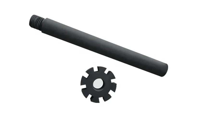
Graphite degassing shafts and rotors form the core moving components inside rotating-degassing systems that treat molten aluminum. The rotor, sometimes called the impeller, disperses an inert gas into the melt by shearing the gas into fine bubbles. The shaft transmits mechanical drive into the melt while holding the rotor in correct position. Together these elements perform rapid gas-liquid contact, accelerating diffusion of dissolved hydrogen from inside the metal to bubble surfaces, which then rise and escape at the metal surface. High-quality manufacture and tailored geometry determine bubble size distribution, homogeneity of treatment, and operating longevity.
2. Why graphite is chosen for degassing hardware
Graphite offers a unique combination of properties that suit molten aluminum environments:
-
Thermal stability at furnace and ladle temperatures.
-
Excellent thermal shock resistance and low thermal expansion in many fine-grain grades.
-
Low chemical affinity with aluminum and high purity availability, reducing contamination risk.
-
Good machinability for precise impeller profiles and concentric shafts.
-
Intrinsic lubricity that reduces bearing friction where components abut.
These practical benefits lead many suppliers and foundries to prefer graphite for rotors and tubes, with engineered coatings now extending service life under abrasive and oxidative stress. Industry suppliers describe graphite rotor assemblies and coated shaft systems as standard components in modern degassing units.
3: Typical graphite grades and material properties
Graphite is offered in molded, isostatic and extruded variants. Properties vary with manufacturing route and raw material selection. The table below summarizes common categories and representative properties for selection purposes.
| Grade type | Typical manufacture | Bulk density (g/cm³) | Typical porosity | Strength comment | Typical use case |
|---|---|---|---|---|---|
| Fine-grain molded graphite | Pressed then baked, sometimes impregnated | 1.75–1.85 | Low to moderate | Good machinability, decent strength | Standard rotors for general purpose |
| Isostatic graphite | Isostatic pressing, high purity | 1.85–1.95 | Very low | High isotropic strength, long life | High-wear environments, premium rotors |
| Extruded graphite | Extruded billets, lower density | 1.6–1.75 | Higher | Lower strength, cheaper | Low-cost short-run rotors |
| Silicon carbide/graphite blends | Isostatic or bonded | 1.9–2.2 | Low | Improved wear resistance | Severe abrasion, long-life applications |
Notes: numerical ranges are indicative. For final specification, request supplier mechanical and microstructural data for the selected grade.

4. Manufacturing methods and surface protections
Manufacturing methods determine microstructure, machinability and in-service durability.
-
Machined graphite: Started from large blocks, then precision turned and milled to shape. Offers dimensional accuracy but may contain machining-induced microcracks if not carefully processed.
-
Isostatic pressing: Powder compacted under uniform pressure, then sintered. Results in near-isotropic strength and lower porosity. Favored when long life and resistance to mechanical shock are priorities. Industry reports indicate that switching to isostatic or SiC-graphite blends can reduce consumption and shaft failures.
Common protective systems
-
Resin impregnation: Fills surface porosity to reduce oxidation and metal infiltration.
-
Ceramic or RFM coatings: Reinforced fiberglass material coverings or specialized ceramic finishes reduce surface erosion and extend life. For example, some manufacturers advertise proprietary TRIPLEX protection or RFM coverings to increase rotor and shaft service life.
5: How graphite rotors remove hydrogen and inclusions
Rotational motion forces injected inert gas into the melt at the rotor tip, breaking the gas stream into many small bubbles. The efficiency of hydrogen removal depends on three linked phenomena:
-
Bubble surface area available for mass transfer. Smaller bubbles provide more surface area per unit gas volume, increasing hydrogen capture.
-
Residence time of bubbles inside the melt column. Proper rotor design keeps bubbles in the active zone long enough to approach equilibrium hydrogen partial pressure.
-
Bubble rise and removal at the surface. Adequate agitation prevents bubble coalescence and encourages steady transport towards the surface.
Physical modelling and experimental studies show rotor geometry and operational parameters produce large differences in refining outcomes. A recent physical-modelling paper demonstrated that pump-type rotor shapes and optimized operating parameters produced a notable improvement in dispersion uniformity and refining efficiency.
6. Rotor geometry, bubble size and performance relationships
Rotor geometry strongly influences bubble formation, dispersion patterns and the final melt quality. Below is a simplified relationship table showing how common geometric features affect bubble size and mixing.
| Geometry feature | Typical effect on bubble size | Effect on dispersion & mixing |
|---|---|---|
| Sharp-edged radial blades | Smaller initial bubble filaments | High shear, effective breakup, increased surface area |
| Rounded-blade profiles | Medium bubble sizes | Smoother flow, reduced shear stress |
| Multi-stage (cascade) vanes | Smaller, more uniform bubbles | Wide dispersion, improved homogeneity |
| Axial vane designs | Larger bubbles | Faster transport but lower mass transfer |
| Porous or slug-type impellers | Very small bubbles with fine dispersion | Excellent mass transfer, potential clogging if not matched to gas supply |
Designers select geometry based on required bubble size spectrum, melt volume, and acceptable pressure drop. CFD and water-model tests are commonly used to validate chosen geometry prior to manufacture.
7: Matching gas type, flow rate and rotor speed to melt volume
Choice of inert gas: most furnaces use nitrogen for cost-effectiveness, while argon provides faster refining in some alloys and critical applications. Gas purity and injection strategy influence efficiency. Typical practical rules:
-
Small melt batches and critical alloy grades: consider argon injection at controlled low flow with a rotor geometry focused on fine bubble production.
-
Large-volume continuous operations: nitrogen often provides sufficient performance with a rotor optimized for throughput and homogeneous mixing.
Operational parameters are interdependent. Example ranges used in industry practice:
-
Rotation speed: 200–1200 rpm depending on rotor size and design.
-
Gas flow: 2–10 L/min per kg of melt treated, scaled by process and alloy.
These numbers represent practical starting points. Always validate via melt hydrogen measurement and time trials. Suppliers typically provide recommended parameter maps for each rotor model.
8. Installation, alignment and mechanical considerations
Key mechanical considerations for reliable operation:
-
Concentricity: shaft-runout and rotor concentricity must stay within supplier tolerances to avoid vibration and premature wear.
-
Seals and bearings: select temperature-rated packings and bearings, recognizing graphite components may be lighter and impose different dynamic loads.
-
Drive coupling: torque capacity should permit rotor start-up load plus safety margin.
-
Insertion depth: correct immersion level determines the active treatment zone and optimal bubble residence time. Supplier charts often give step-by-step insertion guidelines.
9. Wear modes, common failure causes and troubleshooting
Graphite components experience multiple wear mechanisms. Identifying mode helps prescribe countermeasures.
| Wear mode | Symptoms | Typical causes | Mitigation |
|---|---|---|---|
| Oxidative degradation | Surface roughening, mass loss | Exposure to oxidizing gases or air at temperature | Apply impregnation or protective coating, ensure inert cover |
| Abrasive erosion | Shape loss, dimensional change | Solid inclusions, high-speed melt flow | Use denser grade or SiC-blend graphite, adjust rotor speed |
| Mechanical cracking | Radial fractures, sudden failure | Impact, improper machining, thermal shock | Improve handling, specify isostatic grade, tolerance checks |
| Chemical attack | Surface pitting | Contaminated fluxes, aggressive reagents | Review flux chemistry, limit direct contact |
| Thread or coupling failure | Loose rotor/shaft interface | Over-torque or misalignment | Torque control, alignment checks |
Frequent causes of shortened service life include misalignment, improper oxidation protection, and wrong grade selection for high-wear melts. Upgrading to an isostatic grade or adopting a silicon carbide-graphite composite has reduced failures in reported cases.
10. Maintenance, inspection and replacement planning
Routine inspection extends life and prevents unplanned shutdowns. A practical maintenance schedule:
| Interval | Check list |
|---|---|
| Daily | Visual rotor condition, gas flow stability, drive vibration levels |
| Weekly | Measure rotor concentricity, inspect mounting threads, verify gas purity |
| Monthly | Measure rotor dimensions against wear limits, check surface coating integrity |
| Quarterly | Replace seals, inspect shaft for corrosion, perform trial degassing and hydrogen measurement |
| End-of-life criteria | Rotor diameter reduction beyond tolerance, deep surface cracking, repeated oxidation pitting |
Record findings and operate an inventory of spare rotors to avoid production stoppage. Many foundries track cumulative operating hours per rotor and retire components on a “hours plus condition” basis.
11. Comparative analysis: graphite versus alternatives
Key tradeoffs summarized:
-
Graphite: excellent balance of machinability, thermal behavior, and cost. Coating options extend life.
-
Silicon carbide-graphite blends: higher wear resistance, good for abrasive melts, higher initial cost. Some foundries reported significant reductions in downtime after switching to SiC-graphite.
-
Ceramic rotors: exceptional wear resistance but brittle; may need special mounting and risk sudden fracture.
-
Metal impellers: used in some non-aluminum melts; not common for molten aluminum due to wettability and contamination risk.
Selection depends on melt chemistry, abrasive inclusions, and acceptable replacement cadence.
12. Case study summaries and research findings
Selected industry findings:
-
Atech and other established suppliers document the benefits of tailored graphite rotor geometry and RFM/impregnation coatings for extended service life and consistent refining performance. Supplier technical datasheets emphasize precision machining and protective covering.
-
A Nature-indexed experimental study using physical water modelling found that rotor geometry strongly affects dispersion uniformity and refining efficiency. Adopting optimized pump-type rotor shapes improved overall melt treatment in scaled trials. This supports the common industry practice of validating rotor designs in model rigs prior to full-scale deployment.
-
Industrial reports highlight that replacing machined graphite rotors with one-piece isostatic SiC/graphite blends cut rotor-related downtime in automotive casting operations. This points to long-term operational savings when higher upfront cost is balanced against reduced replacement frequency.
13: Selection checklist for purchasing or specifying rotors and shafts
When specifying or procuring graphite rotors and shafts, include this checklist in RFQs:
-
Melt alloy and typical cleanliness targets (maximum acceptable hydrogen ppm).
-
Rotor geometry drawing or target bubble size distribution.
-
Graphite grade and porosity requirement.
-
Surface protection or impregnation requirement.
-
Expected operating rpm and peak torque.
-
Insertion depth and mounting schema.
-
Acceptance tolerances for concentricity and runout.
-
Proof of dimensional or mechanical testing and traceability.
-
Packaging and shipping instructions to prevent damage.
-
Warranty and expected service life metrics under stated operating conditions.
14: Environmental, safety and handling notes
Handling graphite hardware requires care:
-
Graphite dust can be harmful when airborne; use local extraction when cutting or grinding, and provide PPE.
-
Prevent water ingress into hot graphite; thermal shock risk increases if wet parts heat rapidly.
-
Dispose of contaminated graphite following local regulations if it carries hazardous residues from the melt.
-
Store rotors in dry, temperature-stable conditions and protect machined surfaces.
15. Multiple tables for quick reference
Table A: Representative material property comparison
| Property | Fine-grain graphite | Isostatic graphite | SiC-graphite blend |
|---|---|---|---|
| Density (g/cm³) | 1.72–1.85 | 1.85–1.95 | 1.9–2.20 |
| Compression strength (MPa) | 30–80 | 60–120 | 100–180 |
| Porosity | Moderate | Low | Low |
| Wear resistance | Medium | High | Highest |
| Typical cost | Low–medium | Medium–high | High |
Table B: Quick troubleshooting guide
| Symptom | Likely cause | Immediate check |
|---|---|---|
| Poor hydrogen removal | Wrong rotor geometry or low gas dispersion | Verify rotor rpm, gas flow rate, bubble visibility if possible |
| Fast rotor wear | Abrasive inclusions or oxidizing environment | Inspect melt flux, check impregnations and coatings |
| Vibration | Misalignment or runout | Measure shaft concentricity and stud torque |
| Sudden fracture | Thermal shock or impact | Check for pre-existing surface cracks, review handling |
Graphite Rotors & Refining: Operational FAQ
1. How often should a graphite rotor be replaced?
2. Which is better for my plant: Nitrogen or Argon?
3. Can I repair a worn graphite rotor?
4. Does impregnation significantly help rotor life?
5. Are SiC-graphite rotors worth the extra cost?
6. How do I choose the right rotor geometry?
7. What surface protection options exist for rotors?
Common options include:
- Resin Impregnation: For general oxidation resistance.
- RFM (Fiber Reinforced) Coatings: For maximum mechanical protection.
- Ceramic Glazing: To prevent metal adhesion and erosion.
8. Is it OK to run a rotor at higher RPM for better refining?
9. What instrumentation indicates effective degassing?
10. How should I store spare graphite rotors?
Store rotors in a dry, indoor location with cushioned packaging to prevent impact damage. Always keep machined faces wrapped to protect them from environmental moisture and accidental abrasion.
Closing recommendations — practical steps for AdTech customers
-
Specify isostatic graphite or SiC-graphite blend for high-wear melts and consider RFM or other protective coverings for extended life.
-
Validate rotor geometry using a scaled physical model or CFD, focusing on bubble size and distribution uniformity.
-
Maintain a condition-based replacement program rather than a purely time-based schedule. Record hydrogen levels and rotor hours to refine replacement triggers.
-
Request supplier test data and references for the chosen grade and coating before purchase. Where possible, perform a pilot run to compare in-service performance.
