

A caster tip and casting nozzle are precision-engineered refractory or ceramic components that control the flow of molten aluminum from the launder or tundish into the casting mold during continuous casting, and their design directly determines metal flow rate, distribution uniformity, and the final dimensional consistency of cast strip, rod, or billet products. Getting nozzle geometry and caster tip alignment wrong causes some of the most frustrating and recurring problems in aluminum continuous casting, from uneven strip thickness to surface defects that only show up after rolling. We have spent years around continuous casting lines watching operators chase down quality problems that traced back to a worn or improperly sized casting nozzle nobody thought to inspect first, and the pattern repeats often enough that we felt this component deserved a far more thorough breakdown than what currently exists online.
If your project requires the use of Caster Tip, Casting Nozzle, you can contact us for a free quote.
What Caster Tips and Casting Nozzles Actually Do
The casting nozzle sits at the point where molten aluminum transitions from the delivery system, whether that’s a tundish, launder, or distribution trough, into the actual casting zone where solidification begins. Its job sounds simple on paper: control how much metal flows, in what pattern, and at what velocity, into the mold or between casting rolls. In practice, this component has to manage that flow with remarkable precision because even small inconsistencies in flow rate or distribution translate directly into thickness variation, surface defects, or internal structural problems in the finished product.
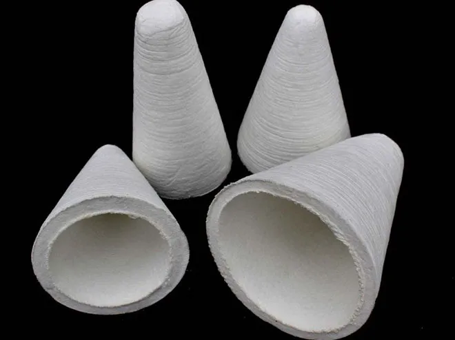
The caster tip, sometimes used interchangeably with nozzle depending on the specific casting process and regional terminology, refers more specifically to the precisely shaped delivery point that meters metal directly into the casting gap in twin-roll or belt casting configurations. Where a nozzle in slab or billet casting might deliver metal into a relatively open mold cavity, a caster tip in strip casting has to deliver an extremely thin, uniform curtain of metal directly into a narrow, rapidly closing gap between rotating casting rolls, which demands tighter tolerances and more sophisticated internal flow channel design.
We think the terminology confusion in this space causes real procurement headaches. A buyer searching for “casting nozzle” might receive quotes for components designed for entirely different casting geometries, and without understanding the functional distinction between components used in DC (direct chill) casting versus continuous strip casting, it’s easy to end up specifying the wrong part entirely.
| Component | Primary Casting Method | Core Function |
|---|---|---|
| Distribution nozzle | DC billet/slab casting | Distributes metal evenly across mold width |
| Caster tip | Twin-roll strip casting | Meters thin metal curtain into roll gap |
| Submerged entry nozzle | Some continuous slab processes | Delivers metal below existing pool surface |
| Combination bag/nozzle assembly | Belt casting systems | Controls flow onto moving casting belt |
How Continuous Casting Flow Control Works
Understanding the flow control mechanism helps explain why nozzle design carries so much weight in overall casting quality. In most aluminum continuous casting configurations, molten metal arrives at the casting zone under some combination of gravity head pressure and controlled flow restriction, and the nozzle’s internal geometry is what converts that incoming flow into the specific pattern needed at the point of solidification.
For DC casting of billets and slabs, metal typically flows from a launder through a distribution system that might include a combination bag or trough designed to equalize flow across the width of a rectangular mold before passing through a final nozzle or a series of nozzle outlets positioned to distribute metal evenly rather than concentrating flow at one point, which would cause uneven solidification and internal defects.
For twin-roll strip casting, the caster tip has an entirely different challenge. Metal needs to enter the narrow gap between two counter-rotating, water-cooled rolls as an extremely thin, laminar sheet, without turbulence, without uneven distribution across the roll width, and at a flow rate precisely matched to the casting speed and roll gap setting. Even minor turbulence at this stage can introduce oxide entrainment or uneven solidification that shows up as visible banding defects in the final strip.
| Casting Configuration | Flow Delivery Challenge | Typical Flow Rate Range |
|---|---|---|
| DC billet casting | Even distribution across circular/rectangular mold | Varies by billet diameter, typically moderate flow |
| DC slab casting | Uniform flow across wide, thin mold cavity | Higher volume, wide distribution needed |
| Twin-roll strip casting | Ultra-thin laminar curtain into roll gap | Precisely metered, low turbulence critical |
| Belt casting | Controlled sheet flow onto moving belt | Moderate, matched to belt speed |
We watched a strip casting line struggle with intermittent thickness variation for weeks before someone finally pulled the caster tip for inspection and found a subtle internal erosion pattern that had developed asymmetrically, favoring flow toward one side of the roll gap without being visually obvious from the outside. Once replaced, the thickness variation that had been blamed on roll gap calibration and cooling water flow disappeared almost immediately.
Materials Used in Caster Tips and Nozzles
Material selection for caster tips and nozzles balances several competing requirements: resistance to erosion from continuous molten aluminum contact, thermal shock tolerance during startup and shutdown cycles, dimensional stability at operating temperature, and non-reactivity with the aluminum alloy being cast to avoid contamination.
Refractory ceramic materials, particularly boron nitride composites, fiber-reinforced ceramics, and various proprietary refractory blends, dominate this application. Boron nitride based materials have become particularly popular for caster tips in strip casting applications due to their excellent non-wetting characteristics with molten aluminum, meaning the metal doesn’t adhere readily to the internal flow channel surfaces, reducing buildup and maintaining consistent flow geometry over a longer service period.
| Material Type | Key Property | Typical Application |
|---|---|---|
| Boron nitride composite | Non-wetting, good thermal shock resistance | Strip casting caster tips |
| Fiber-reinforced ceramic | High mechanical strength, moderate erosion resistance | DC casting nozzles, distribution systems |
| Silicon nitride based ceramic | High temperature stability, good wear resistance | High-volume continuous casting nozzles |
| Refractory castable composite | Cost-effective, moderate performance | General purpose distribution components |
| Graphite-ceramic hybrid | Good thermal conductivity management | Specialty applications requiring controlled cooling |
The non-wetting property deserves extra attention because it directly affects service life and casting quality consistency. Materials that allow aluminum to wet and adhere to internal surfaces gradually build up deposits that narrow flow channels, change internal geometry, and eventually alter the flow pattern delivered to the casting zone, degrading quality gradually in a way that’s hard to detect until defects become obvious in finished product.
We generally steer clients away from lower-cost refractory options for high-volume continuous operations once we calculate the total cost including more frequent replacement cycles and the quality inconsistency that comes with faster internal geometry degradation, even though the upfront unit price looks attractive on a quote sheet.
Types of Casting Nozzles for Different Casting Methods
Aluminum continuous casting covers several distinct process types, and nozzle design varies considerably between them.
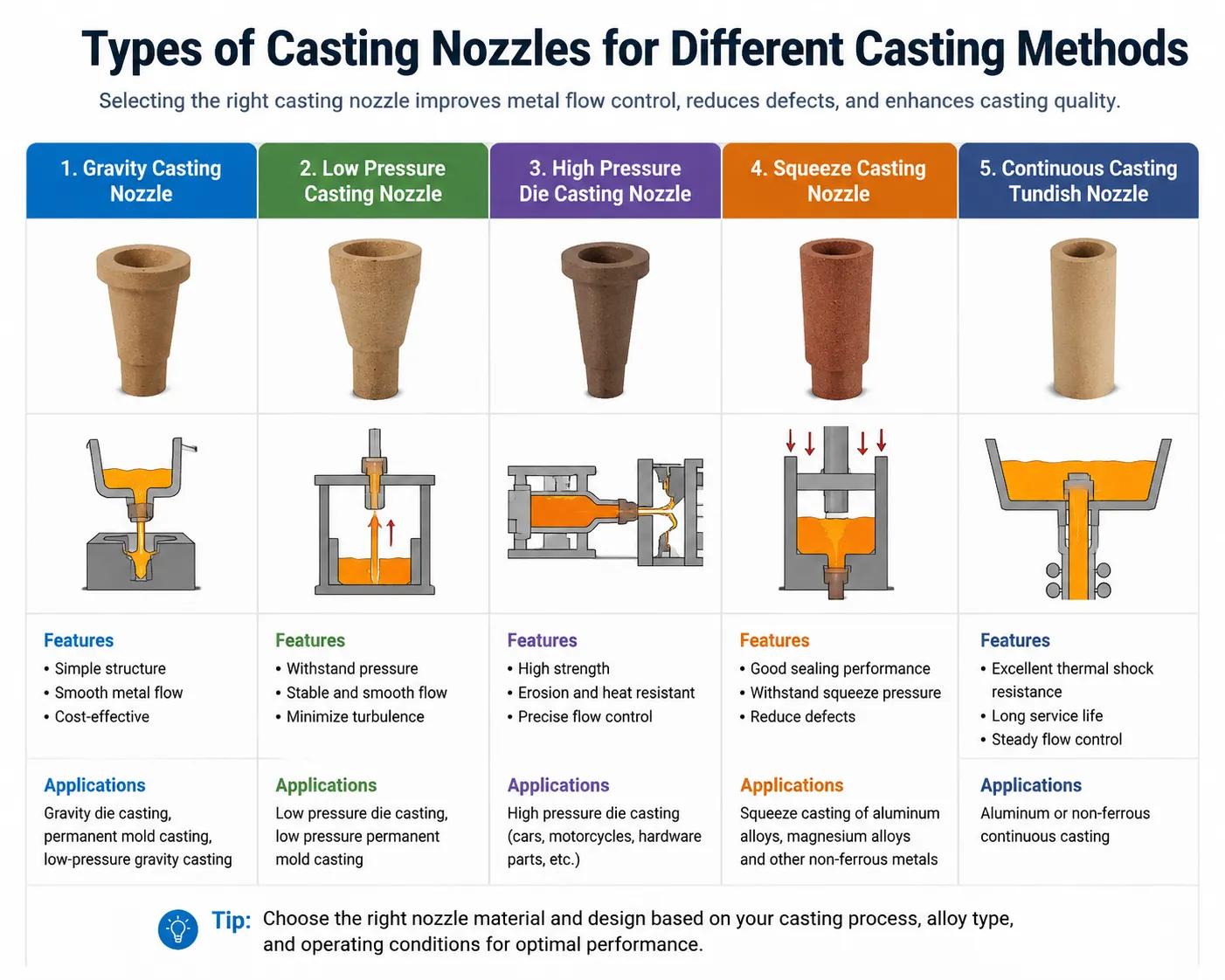
Submerged nozzles deliver metal below the surface of the existing metal pool in the mold, reducing surface turbulence and oxide entrainment compared to open pouring. This design works well for DC slab casting where surface quality directly affects downstream rolling performance.
Open pour distribution nozzles deliver metal from above without submersion, generally used in simpler billet casting setups where the additional complexity of submerged delivery isn’t justified by the production requirements or alloy sensitivity involved.
Caster tips for twin-roll casting represent the most geometrically specialized category, typically featuring a long, narrow slot opening precisely matched to the roll face width, with internal flow channels designed to equalize pressure and velocity across that entire width before the metal exits into the roll gap.
Combination bag and nozzle assemblies used in some belt casting and specialty continuous casting configurations integrate a flow distribution chamber directly with the final delivery nozzle, reducing the number of separate transition points metal has to pass through before reaching the casting zone.
| Nozzle Type | Casting Application | Distinguishing Feature |
|---|---|---|
| Submerged entry nozzle | DC slab casting | Delivers below existing pool surface |
| Open distribution nozzle | Billet casting | Simple design, gravity-fed delivery |
| Twin-roll caster tip | Thin strip casting | Long narrow slot, precise width matching |
| Combination bag/nozzle | Belt and specialty casting | Integrated distribution and delivery |
| Multi-strand distribution nozzle | Multiple billet casting | Splits flow evenly to multiple casting points |
Nozzle Geometry and Its Effect on Metal Distribution
The internal shape of a nozzle or caster tip determines far more than simple flow rate, it controls velocity profile, turbulence characteristics, and distribution uniformity, all of which show up as measurable quality differences in the finished cast product.
Slot width and length in a strip casting caster tip need precise matching to the roll face dimensions. Too narrow relative to the roll width leaves edge regions underfed, causing thin edges or edge cracking during subsequent rolling. Too wide causes metal to overflow beyond the intended casting zone, creating waste and potential safety hazards from molten metal spillage.
Internal flow channel taper affects velocity distribution across the nozzle width. A poorly designed taper can cause metal to flow faster through the center than the edges, or vice versa, creating a non-uniform curtain that translates into thickness variation across the strip width even when overall flow rate measurements look correct.
Exit lip design, the precise shape where metal actually leaves the nozzle or caster tip, influences how cleanly the metal stream separates from the refractory surface. A poorly shaped exit can cause dripping, uneven stream breakup, or metal clinging to the lip surface that eventually builds into a deposit affecting flow consistency.
| Geometry Feature | Effect on Casting Quality | Common Problem if Incorrect |
|---|---|---|
| Slot width matching | Edge quality, width utilization | Edge cracking, underfeeding at edges |
| Internal taper design | Cross-width velocity uniformity | Thickness variation across strip width |
| Exit lip shape | Clean stream separation | Dripping, deposit buildup, flow instability |
| Overall channel length | Flow stabilization before exit | Turbulence carrying into casting zone |
| Wall thickness consistency | Thermal uniformity across width | Localized hot/cold spots affecting solidification |
We worked through a thickness variation problem with a strip casting operation where the issue traced back to a caster tip that had been resurfaced improperly after a previous wear cycle, altering the internal taper just enough to shift velocity distribution toward one edge. The measurement equipment showed correct total flow rate throughout, which is exactly why the problem took so long to diagnose, nobody was looking at distribution uniformity specifically since the aggregate numbers looked fine.
Caster Tip Design for Thin Strip and Foil Casting
Thin strip and foil casting applications push caster tip design requirements further than thicker gauge production, since the tolerances for acceptable variation shrink proportionally as target thickness decreases.
For strip casting targeting final gauges in the range that eventually gets rolled down to foil stock, caster tip slot opening precision becomes critical, often requiring tolerances measured in fractions of a millimeter across the entire width of the tip. Even minor inconsistency at this stage compounds through subsequent rolling passes, meaning a small caster tip defect can produce a proportionally larger final product quality problem once the material has been reduced through multiple rolling stands.
Material selection also becomes more critical for thin gauge applications, since any tendency toward metal adhesion or gradual erosion changes the delivery geometry faster relative to the tight tolerance window these applications demand. Foundries running dedicated foil stock production lines often specify premium boron nitride composite caster tips specifically because the extended dimensional stability justifies the higher material cost when weighed against the quality consequences of tip degradation on such thin material.
| Casting Target | Caster Tip Tolerance Requirement | Material Preference |
|---|---|---|
| Standard gauge strip (3-10mm) | Moderate precision, standard tolerance | Fiber-reinforced ceramic acceptable |
| Thin gauge strip (1-3mm) | Tight precision required | Boron nitride composite preferred |
| Foil stock precursor (under 1mm target after rolling) | Very tight precision, minimal drift tolerance | Premium boron nitride, frequent inspection |
Alignment and Positioning Requirements
Even a perfectly manufactured caster tip or nozzle underperforms if installed with incorrect alignment relative to the mold, casting rolls, or belt system it’s feeding metal into. Alignment issues represent one of the more common and preventable sources of casting quality problems we encounter during troubleshooting visits.
For twin-roll casting, the caster tip needs precise positioning relative to both the roll gap centerline and the roll face width, with even minor misalignment causing asymmetric metal distribution that no amount of downstream process adjustment can fully correct. Vertical positioning relative to the roll nip point also matters significantly, since delivering metal too far from or too close to the actual solidification point changes the effective casting behavior even with an otherwise correctly designed tip.
For DC casting configurations, nozzle alignment relative to mold centerline affects flow symmetry, and any offset tends to create asymmetric solidification patterns that can manifest as dimensional inconsistency or internal structural non-uniformity in the cast billet or slab.
| Alignment Parameter | Consequence if Incorrect | Recommended Check Frequency |
|---|---|---|
| Horizontal centerline position | Asymmetric metal distribution | Every tip/nozzle change, periodic verification |
| Vertical distance to solidification point | Altered casting behavior, quality drift | Initial setup, verify after any equipment adjustment |
| Angular orientation | Uneven flow pattern across width | Every installation |
| Gap consistency across nozzle width | Width-wise thickness variation | Precision measurement at installation |
We recommend foundries build alignment verification into their standard changeover procedure rather than treating it as an occasional check, since the labor cost of a quick verification is minimal compared to even a short production run generating out-of-spec material due to an alignment error that went unnoticed.
Signs of Nozzle Wear and When to Replace
Recognizing wear indicators before they cause quality problems saves considerably more than the cost of proactive replacement, and several observable signs typically precede outright failure.
Gradual flow rate drift, where achieving the same target flow requires increasingly different valve or head pressure settings compared to when the nozzle was new, often indicates internal channel erosion or deposit buildup changing the effective flow geometry.
Visible surface pitting or erosion patterns on the internal flow surfaces, observable during scheduled inspection when the caster tip or nozzle is removed for cleaning or replacement, indicate progressive wear that will eventually affect flow consistency even before quality problems become obvious in production.
Asymmetric wear patterns, particularly relevant for wide caster tips in strip casting, sometimes develop due to slightly uneven flow distribution from the upstream delivery system, and these asymmetric patterns tend to accelerate over time as the developing irregularity itself further concentrates flow toward the more eroded region.
Quality metric drift in finished product, including thickness variation trends, surface defect rate increases, or edge quality degradation that develops gradually over a production campaign rather than appearing suddenly, often correlates with progressive nozzle wear even when the component hasn’t reached obvious visible failure.
| Wear Indicator | What It Suggests | Recommended Response |
|---|---|---|
| Flow rate requiring adjustment over time | Internal geometry change from erosion/buildup | Schedule inspection, consider replacement |
| Visible internal pitting/erosion | Progressive material degradation | Assess remaining service life, plan replacement |
| Asymmetric wear pattern | Uneven upstream flow distribution | Check upstream delivery system alongside nozzle replacement |
| Gradual quality metric drift | Cumulative effect of wear approaching critical threshold | Investigate immediately, don’t wait for obvious failure |
| Visible cracking or chipping | Imminent failure risk | Replace immediately before continued production |
Benefits of Proper Nozzle Selection and Maintenance
Foundries that approach caster tip and nozzle selection and maintenance systematically rather than reactively see consistent benefits across several quality and operational metrics.
Improved dimensional consistency: Properly matched and well-maintained nozzles produce more consistent thickness and width measurements across a production run, reducing the trim losses and rework associated with out-of-spec sections.
Reduced surface defect rates: Consistent, low-turbulence flow delivery reduces oxide entrainment and surface irregularities that would otherwise require additional downstream processing or cause outright rejection.
Extended production run length: Nozzles selected with appropriate wear resistance for the specific production volume allow longer continuous operation between changeovers, improving overall line utilization.
Lower scrap and rework costs: Consistent quality directly reduces the volume of material that fails to meet specification and either requires reprocessing or gets scrapped entirely.
Predictable maintenance scheduling: Understanding wear patterns and establishing proactive replacement schedules based on actual service life data, rather than reacting to failures, allows better production planning and reduces unplanned downtime.
| Benefit Area | Typical Improvement Reported |
|---|---|
| Thickness variation reduction | 15% to 30% tighter tolerance achievement |
| Surface defect rate | 10% to 25% reduction |
| Production run length between changeovers | Extended by 20% to 50% depending on material upgrade |
| Unplanned downtime from nozzle failure | Significantly reduced with proactive replacement scheduling |
| Overall scrap rate | Measurable reduction correlating with flow consistency improvement |
Common Problems Traced Back to Nozzle Issues
Certain recurring casting defects trace back to caster tip or nozzle problems more often than operators initially suspect, since the symptoms often appear downstream from the actual root cause.
Edge cracking in rolled strip products frequently originates from underfed edge regions caused by caster tip slot width mismatch or asymmetric wear concentrating flow toward the center of the width. Operators sometimes chase this problem through rolling parameter adjustments without checking the upstream casting delivery component first.
Banding defects, visible as periodic surface irregularities running across the strip width, often correlate with flow instability at the caster tip, sometimes from partial deposit buildup creating intermittent flow disruption rather than a steady-state problem that would be easier to diagnose.
Center-to-edge thickness variation across strip width typically points directly to internal nozzle geometry issues, whether from original design mismatch, installation misalignment, or progressive wear altering the intended flow profile.
Intermittent flow interruption or surging, sometimes mistaken for upstream furnace or launder problems, can originate from partial blockage within the nozzle from oxide buildup or refractory degradation creating an unstable flow path.
| Downstream Symptom | Nozzle-Related Root Cause to Check |
|---|---|
| Edge cracking after rolling | Slot width mismatch, asymmetric edge wear |
| Periodic surface banding | Flow instability, intermittent deposit disruption |
| Cross-width thickness variation | Internal geometry mismatch, alignment error |
| Intermittent flow surging | Partial blockage, oxide buildup within flow channel |
| Gradual quality drift over production run | Progressive erosion or deposit accumulation |
Installation and Setup Procedures
Proper installation technique significantly affects both immediate performance and service life, and we’ve found that standardizing this procedure across shift teams eliminates a surprising amount of variability that otherwise gets misattributed to equipment or material problems.
Preheating the caster tip or nozzle before contact with molten metal prevents thermal shock cracking, similar to the preheating requirements for ceramic filtration components discussed in related casting equipment applications. The preheat temperature and duration should match manufacturer specifications for the specific refractory material being used, since different ceramic compositions have different thermal shock tolerance characteristics.
Alignment verification during installation, using appropriate measurement tools rather than visual estimation, confirms the component sits correctly relative to the mold, rolls, or belt system before production begins. This step takes only a few extra minutes but catches misalignment issues before they generate out-of-spec production.
Initial flow testing at reduced rate before ramping to full production speed allows operators to verify the installation is performing as expected and catch any immediate problems, such as unexpected asymmetric flow or leakage, before committing to full-scale production that would generate larger volumes of potentially defective material if something is wrong.
| Installation Step | Purpose | Common Shortcut That Causes Problems |
|---|---|---|
| Component preheating | Prevents thermal shock cracking | Skipping or rushing preheat cycle |
| Dimensional alignment check | Ensures correct positioning | Relying on visual estimation instead of measurement |
| Seal/gasket inspection | Prevents leakage around component | Reusing degraded sealing material |
| Reduced-rate initial flow test | Catches installation problems early | Jumping directly to full production speed |
| Documentation of installation date/batch | Enables service life tracking | Failing to log installation for future reference |
Cost Considerations and Service Life Expectations
Caster tip and nozzle costs vary considerably based on material composition, size, and geometric complexity, and buyers should evaluate total cost of ownership rather than focusing purely on unit purchase price.
| Component Category | Approximate Cost Range | Typical Service Life |
|---|---|---|
| Basic refractory distribution nozzle | Lower cost tier | Shorter, higher replacement frequency |
| Fiber-reinforced ceramic nozzle | Moderate cost tier | Moderate service life |
| Standard boron nitride caster tip | Higher cost tier | Extended service life |
| Premium boron nitride composite (thin gauge application) | Highest cost tier | Longest service life, tightest tolerance retention |
We advise foundry buyers to calculate cost per ton of metal cast rather than cost per component when comparing options, since a more expensive caster tip that lasts three times longer while maintaining tighter tolerance can easily produce lower total cost despite the higher individual purchase price. This calculation becomes even more favorable when the quality improvement from better tolerance retention reduces scrap and rework costs on top of the direct replacement frequency savings.
Procurement Guidance for Buyers
Sourcing caster tips and nozzles requires more technical specification exchange than many general refractory purchases, since these components need precise matching to specific casting equipment dimensions and production parameters.
Provide suppliers with complete dimensional specifications for your casting equipment, including roll face width and gap settings for strip casting applications, or mold dimensions and flow requirements for DC casting setups, rather than assuming a standard catalog size will fit correctly.
Request material composition documentation and thermal shock resistance data specific to your operating temperature range and alloy composition, since some refractory formulations perform notably differently depending on the specific aluminum alloy chemistry they contact regularly.
Ask about dimensional tolerance guarantees and quality control procedures the manufacturer follows, since inconsistency between supposedly identical components from batch to batch can introduce exactly the kind of intermittent quality problems that are difficult to trace back to their source.
| Procurement Item to Request | Purpose |
|---|---|
| Complete casting equipment dimensional specifications | Ensures correct fit and geometry matching |
| Material composition and thermal shock data | Confirms compatibility with your operating conditions |
| Batch-to-batch dimensional tolerance documentation | Reduces intermittent quality variation risk |
| Recommended preheat and installation procedure | Ensures proper handling from first use |
| Expected service life data under comparable conditions | Supports accurate total cost of ownership calculation |
Frequently Asked Questions
What is the difference between a caster tip and a casting nozzle?
The terms overlap significantly, but caster tip generally refers to the precise delivery component used in twin-roll strip casting that meters metal into the roll gap, while casting nozzle more broadly describes flow control components used across various continuous casting configurations including DC billet and slab casting.
How often should a caster tip be replaced in continuous strip casting?
Replacement frequency depends on material composition, production volume, and alloy being cast, but many operations establish schedules ranging from a single extended production campaign to multiple weeks of continuous operation, with premium boron nitride composite tips generally lasting longer than basic refractory alternatives.
Can a worn casting nozzle be repaired rather than replaced?
Some nozzles can undergo resurfacing or minor repair, but this requires precise control to avoid altering the internal geometry that determines flow characteristics. Improperly executed repairs can introduce new quality problems, so repair should only be attempted by qualified refractory service providers with appropriate equipment.
What causes uneven thickness across the width of cast aluminum strip?
Cross-width thickness variation commonly traces back to caster tip internal geometry problems, including taper design flaws, alignment errors, or asymmetric wear that creates uneven flow velocity distribution across the tip width.
Does the aluminum alloy being cast affect nozzle material selection?
Yes, alloy composition, particularly reactive elements like magnesium, can interact differently with various refractory materials, and some alloy systems require specific nozzle material formulations to avoid contamination or accelerated erosion.
How do I know if my current caster tip is causing quality problems versus other equipment?
Systematic troubleshooting comparing quality metrics before and after nozzle inspection or replacement, combined with visual examination of the internal flow surfaces for erosion or deposit buildup, typically isolates whether the nozzle is the root cause versus other casting line variables.
What is the typical lead time for ordering replacement caster tips?
Lead times vary by manufacturer and component complexity, but custom-sized or specialty material caster tips often require several weeks for production, making it advisable to maintain spare inventory for critical production lines rather than ordering reactively after failure.
Can nozzle problems cause defects that only appear after downstream rolling?
Yes, subtle casting delivery inconsistencies that aren’t severe enough to cause obvious problems in the as-cast material can still create underlying non-uniformity that becomes visible as edge cracking, banding, or thickness variation after the material undergoes subsequent rolling reduction.
Is boron nitride always the best material choice for aluminum casting nozzles?
Boron nitride composites offer excellent non-wetting and thermal shock properties particularly valuable for thin gauge strip casting, but the higher cost isn’t always justified for less demanding applications like general billet casting, where fiber-reinforced ceramic alternatives often provide adequate performance at lower cost.
How does misalignment differ from wear as a cause of casting defects?
Misalignment problems typically appear immediately after installation and remain relatively constant unless equipment shifts further, while wear-related problems develop gradually over a production campaign, worsening progressively as the component degrades, which helps distinguish between the two root causes during troubleshooting.
Closing Thoughts From Our Casting Line Experience
Caster tips and casting nozzles rarely get the attention they deserve relative to their actual influence on final product quality, largely because they sit hidden within the casting equipment and don’t generate the kind of visible, immediate feedback that more obvious process variables produce. Based on what we’ve observed across multiple continuous casting operations, the plants that build systematic inspection, alignment verification, and proactive replacement scheduling around these components consistently outperform those treating nozzle management as a reactive afterthought.
If your operation struggles with recurring quality issues that don’t clearly trace back to obvious process parameters like temperature or casting speed, we’d suggest pulling your caster tip or nozzle for close inspection before assuming the problem lies elsewhere. The component doing the actual work of delivering molten metal into your casting zone deserves to be among the first places you look, not the last.