How to optimize rotary jet degassing process for degassing units part B
How to optimize rotary jet degassing process for degassing units part B
3.1 Influence of bottom clearance on the gas-liquid two-phase flow field
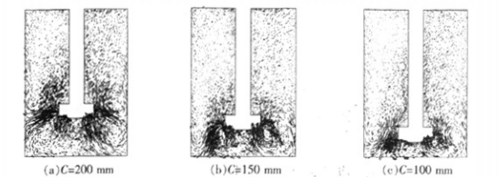
Figure 2 shows the liquid phase velocity distribution in a certain longitudinal section (phase angle θ= 0°.) in the degassing unit with different clearances from the bottom, where the degassing unit is square and the bubble diameter db = 1.0 mm. Since the distribution of the liquid phase velocity field is investigated, only the liquid phase section of the vanadium height where the aluminum melt is located is displayed.

Fig. 2 has a certain longitudinal section 1 MW liquid phase velocity distribution in the degassing unit with no separation from the bottom
It can be seen from Figure 2 that the rotating nozzle generates a high-speed radial jet in the stirring area, and the liquid flow moves with the liquid along the circumference. When it moves to the inner wall of the degassing unit, it is deflected to form a vortex, which is consistent with Khopkar et al. The experimental results for gas-liquid two-phase flow in a stirred tank are similar. However, the radial jet is not discharged horizontally but is deflected downward, and with the reduction of the clearance from the bottom, the degree of deflection increases. Accordingly, the vortex of the produced cattle is closer to the bottom of the degassing unit, so that the aluminum under the rotating nozzle is The melt is thoroughly stirred.

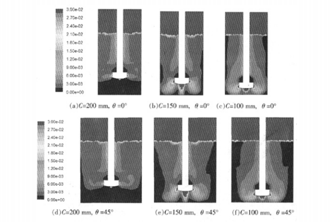
Figure 3 shows the gas volume fraction distribution in different longitudinal sections (θ = 0°or 45°) in the degassing unit with different bottom clearances. The parameters of rotary injection are the same as those in Figure 2.
Fig.3 Distribution of gas volume fractions in different longitudinal sections in degassing units with different bottom clearances
It can be seen from Figure 3 that in the middle of the degassing unit, that is, near the rotating nozzle and the rotating rod, the gas distribution is dense. As the radial distance increases, the gas content gradually decreases to the minimum in the side wall area of the degassing unit, especially 45. The phenomenon of very low gas content in the longitudinal section where the phase angle is located is more significant. This shows that the gas easily escapes from the degassing unit, and the central area floats up to the free liquid surface, causing the aluminum melt in the side wall area to be unable to effectively contact with a sufficient amount of argon, which is not conducive to the elimination of hydrogen, and at 45° phase, This phenomenon is more serious at the angular position.
In addition, the gas distribution in the degassing unit from the bottom clearance has a certain influence. When the gap between the bottom and the bottom is large, the downward deflection of the radial jet is small, causing the gas to move radially outward after being discharged from the air hole, and continue to float up, resulting in a short action time of the bubbles in the melt, and the rotation The melt in the lower part of the nozzle cannot be treated, which reduces the degassing efficiency of unit gas; as the clearance from the bottom decreases, the downward deflection of the radial jet is strengthened, and the gas is blown into the aluminum melt from the gas hole. The trend of α increases and the movement time of the gas in the degassing unit increases accordingly, which is beneficial to the full contact between the gas-liquid two phases to a certain extent and is beneficial to the elimination of hydrogen from the aluminum melt.


