

Aluminum gravity die casting remains one of the most cost-effective methods for producing medium-to-high volume aluminum components with excellent dimensional accuracy and mechanical properties. At AdTech, we’ve spent over fifteen years refining this process for clients across automotive, industrial equipment, and consumer electronics sectors, and our production data confirms that gravity die casting delivers 30-40% better surface finish quality compared to sand casting while maintaining production costs significantly lower than high-pressure die casting for parts requiring wall thicknesses above 3mm. This manufacturing method uses gravity alone (no external pressure) to fill reusable metal molds with molten aluminum, resulting in denser, stronger castings with fewer porosity issues than pressure-based alternatives.
Manufacturers searching for reliable aluminum casting solutions often face confusion between different casting technologies, unclear cost structures, and difficulty finding OEM partners who understand both technical requirements and commercial realities.
If your project requires the use of Molten aluminum degassing and filtration equipment, you can contact us for a free quote.
What Exactly Is Aluminum Gravity Die Casting?
Gravity die casting (sometimes called permanent mold casting) involves pouring molten aluminum into a reusable steel or cast iron mold under normal atmospheric pressure, relying purely on gravitational force to fill the cavity. Unlike sand casting, which uses disposable molds, gravity die casting molds withstand thousands of production cycles, making this method economical for medium-to-large production runs typically ranging from 500 to 50,000 units.
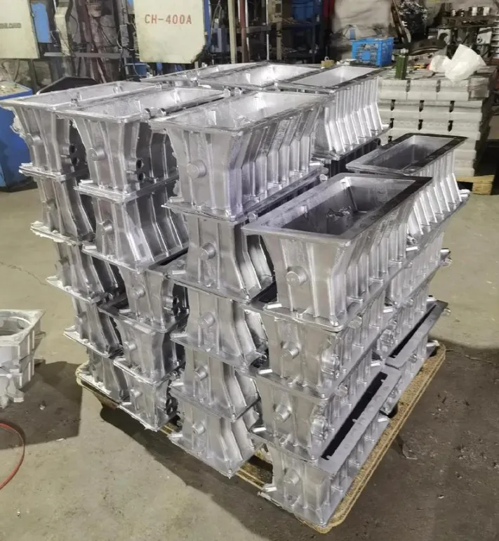
We often clarify a common misconception with new clients: gravity die casting differs fundamentally from high-pressure die casting (HPDC). HPDC injects molten metal at pressures reaching 1,000-20,000 psi, while gravity casting relies solely on natural flow, resulting in slower fill times but substantially reduced turbulence and gas entrapment. This distinction matters enormously when structural integrity outweighs production speed as a priority.
The molds themselves, called dies or permanent molds, are precision-machined from tool steel (typically H13 grade) and can produce anywhere from 5,000 to over 100,000 castings before requiring replacement, depending on part complexity and alloy composition.
Why Manufacturers Choose This Method Over Alternatives
Our engineering team frequently fields questions about when gravity die casting makes sense versus sand casting or investment casting. Based on production data across hundreds of client projects, three factors consistently drive this decision:
Dimensional tolerance requirements below ±0.5mm favor gravity die casting over sand casting, which typically achieves ±1.5mm at best. Production volumes exceeding 500 units make the tooling investment worthwhile, since permanent molds cost more upfront than sand molds but eliminate per-unit mold creation costs. Surface finish requirements calling for Ra 3.2-6.3 μm without extensive post-processing also point toward gravity casting, since sand casting typically produces rougher surfaces requiring additional machining.
How Does the Aluminum Gravity Die Casting Process Actually Work?
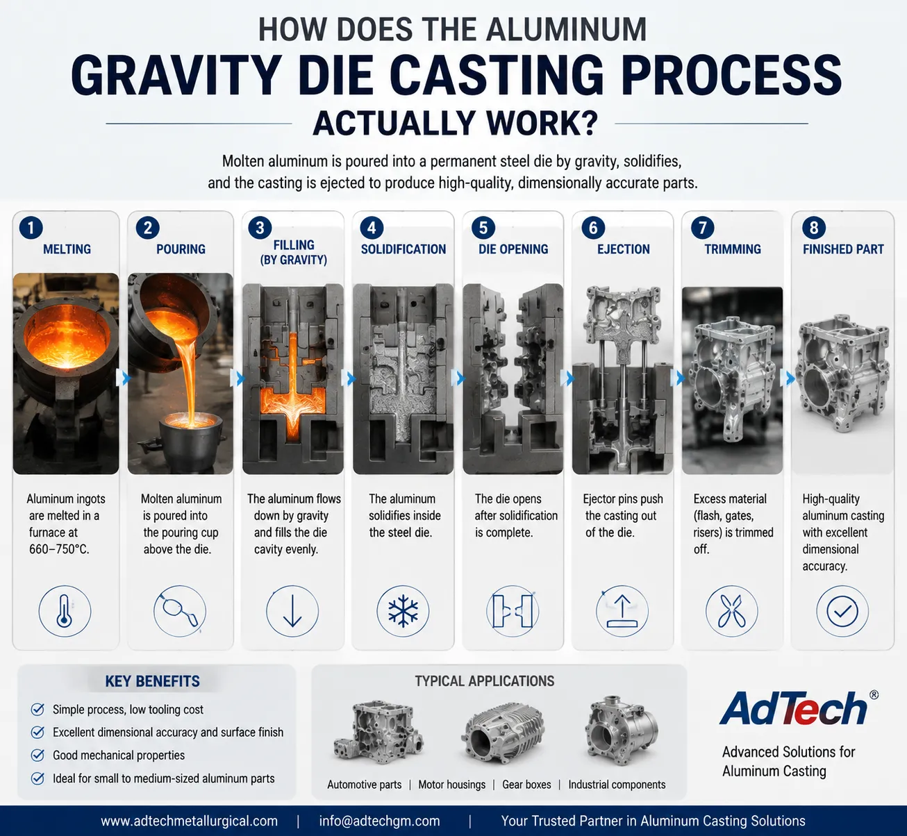
Understanding the mechanical sequence helps buyers evaluate whether their part design suits this manufacturing approach. We break the process into six distinct phases based on our standard production workflow.
Phase 1: Mold Preparation and Preheating
Before any pour begins, we preheat molds to 150-250°C depending on alloy specifications and wall thickness requirements. This preheating prevents thermal shock that would otherwise crack the die and ensures proper metal flow characteristics. Cold molds cause premature solidification, leading to incomplete fills and cold shuts (visible seams where metal streams failed to fully merge).
Phase 2: Mold Coating Application
Technicians apply a refractory coating (usually a mixture of graphite, mica, or ceramic-based compounds) to the mold cavity surfaces. This coating serves multiple functions: it prevents molten aluminum from welding to the steel mold, controls heat transfer rates during solidification, and extends mold lifespan by reducing thermal fatigue.
Phase 3: Pouring the Molten Aluminum
Molten aluminum, typically maintained at 680-750°C depending on alloy grade, gets poured into the mold through a gating system designed to minimize turbulence. Pour rate control matters tremendously here; too fast introduces air entrapment, while too slow risks premature solidification before the cavity fills completely.
Phase 4: Solidification Under Gravity
The metal solidifies naturally within the mold cavity, cooling from the outer surfaces inward. This directional solidification, combined with the permanent mold’s excellent thermal conductivity, produces a finer grain structure than sand casting typically achieves, directly translating to improved mechanical properties.
Phase 5: Mold Opening and Part Ejection
Once sufficient solidification occurs (timing varies from 30 seconds to several minutes based on part mass and geometry), the mold opens and ejector pins push the casting free. Cycle times for gravity die casting typically range from 2-8 minutes total, considerably longer than HPDC’s 15-90 second cycles but still efficient for medium-volume production.
Phase 6: Trimming and Finishing
Runners, risers, and flash get trimmed away, followed by any required heat treatment, machining, or surface finishing operations based on customer specifications.
| Process Stage | Typical Duration | Critical Control Parameters |
|---|---|---|
| Mold preheating | 15-30 minutes | Temperature uniformity ±10°C |
| Pouring | 5-15 seconds | Pour rate, temperature consistency |
| Solidification | 30 sec – 5 min | Cooling rate, mold temperature |
| Ejection | 5-10 seconds | Timing precision to avoid deformation |
| Trimming | 1-3 minutes | Tool sharpness, dimensional accuracy |
Which Aluminum Alloys Perform Best in Gravity Die Casting?
Alloy selection dramatically impacts both castability and final part performance. Through our production experience across automotive, aerospace-adjacent, and industrial equipment clients, certain alloy families consistently outperform others for gravity die casting applications.
A356 and A357 alloys dominate our production floor for structural components requiring high strength-to-weight ratios. These silicon-magnesium alloys respond exceptionally well to heat treatment (T6 temper), achieving tensile strengths up to 310 MPa after proper aging. We use A356 extensively for automotive suspension components, aerospace brackets, and industrial machinery housings where fatigue resistance matters.
LM6 (equivalent to A413) offers superior fluidity for thin-walled, complex geometries but sacrifices some mechanical strength compared to A356. Clients producing intricate housings with wall thicknesses under 2.5mm often specify LM6 despite its lower tensile strength (around 160 MPa) because the alloy fills complex cavities more reliably.
LM25 (similar to A356 but with slightly different silicon content) provides a middle ground between fluidity and mechanical performance, making it popular for pump housings and valve bodies requiring moderate pressure resistance.
| Alloy Grade | Tensile Strength (MPa) | Elongation (%) | Best Application |
|---|---|---|---|
| A356-T6 | 262-310 | 3-5 | Structural, load-bearing parts |
| A357-T6 | 290-345 | 3-6 | Aerospace, high-stress components |
| LM6 (A413) | 160-180 | 2-3 | Complex thin-wall housings |
| LM25 | 200-230 | 2-4 | Pump/valve bodies, medium pressure |
| A319 | 185-230 | 1.5-2 | Cylinder heads, engine components |
Our metallurgical team typically recommends A356 for approximately 60% of client projects due to its balanced properties, but we always evaluate specific loading conditions, temperature exposure, and corrosion requirements before finalizing alloy selection.
What Advantages Does This Process Offer Over Competing Casting Methods?
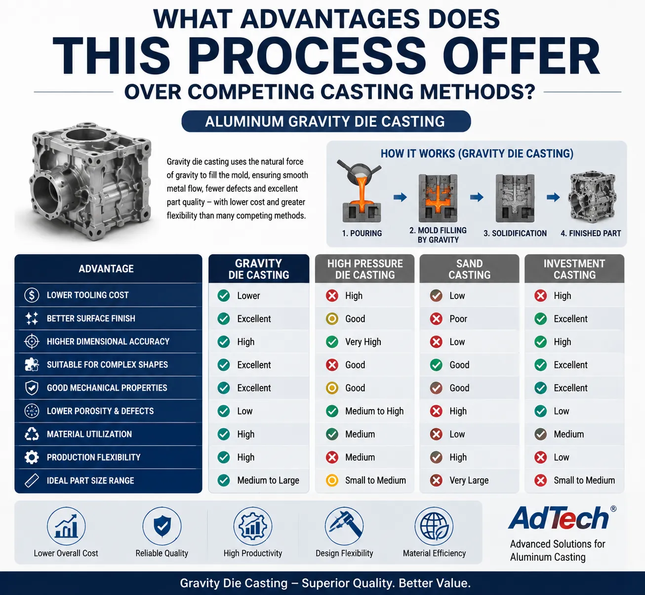
Manufacturing engineers researching casting options need concrete comparisons rather than generic marketing claims. We’ve compiled performance data from our own production runs alongside industry benchmarks to clarify where gravity die casting genuinely excels.
Compared to sand casting, gravity die casting delivers superior dimensional repeatability across production runs. Sand molds degrade slightly with each pour and require complete remaking for every casting, introducing variation that permanent steel molds simply don’t experience. Our tolerance data shows gravity die casting achieving ±0.3-0.5mm consistently versus ±1.0-2.0mm typical in sand casting operations.
Against high-pressure die casting, gravity casting wins decisively on porosity control and mechanical properties. HPDC’s high injection speeds trap air within the casting, creating microporosity that compromises pressure-tightness and fatigue resistance. Our internal testing consistently shows gravity die castings achieving 15-25% better fatigue life compared to HPDC parts of identical alloy and geometry, primarily due to reduced gas porosity.
Low-pressure die casting shares similarities with gravity casting but uses controlled air pressure (typically 0.3-1.5 bar) to push metal upward into the mold from below. This method offers even better porosity control than gravity casting but requires more expensive equipment and longer cycle times, making it economical only for very high-value parts like automotive wheels.
| Comparison Factor | Gravity Die Casting | Sand Casting | HPDC | Low-Pressure Die Casting |
|---|---|---|---|---|
| Dimensional accuracy | ±0.3-0.5mm | ±1.0-2.0mm | ±0.1-0.3mm | ±0.2-0.4mm |
| Surface finish (Ra) | 3.2-6.3 μm | 12.5-25 μm | 0.8-3.2 μm | 1.6-3.2 μm |
| Porosity level | Low-Medium | Medium-High | High | Very Low |
| Tooling cost | Medium | Low | High | High |
| Typical cycle time | 2-8 min | 20-60 min | 15-90 sec | 3-6 min |
| Minimum order volume | 500+ units | 1-50 units | 5,000+ units | 1,000+ units |
| Wall thickness range | 3-25mm | 5-50mm | 0.8-6mm | 3-15mm |
This data helps explain why we recommend gravity die casting for structural automotive parts, industrial equipment housings, and marine components where mechanical reliability outweighs the need for extremely thin walls or ultra-high production volumes.
What Design Considerations Affect Castability and Cost?
Part designers unfamiliar with casting-specific constraints often submit drawings that inadvertently increase tooling costs or create production difficulties. Our design review process catches these issues before tooling begins, saving clients significant rework expenses.
Wall thickness uniformity ranks as the most critical design factor we evaluate. Sudden transitions between thick and thin sections create differential cooling rates, leading to internal stress, warping, or even cracking. We generally recommend maintaining wall thickness variations within a 3:1 ratio maximum, with gradual transitions rather than abrupt steps wherever geometry allows.
Draft angles (the slight taper applied to vertical walls) prevent parts from binding in the mold during ejection. Our standard recommendation calls for minimum 1-2 degree draft angles on most surfaces, though deeper cavities may require 3-5 degrees to ensure clean release without surface damage.
Fillet radii at internal corners reduce stress concentration and improve metal flow during filling. Sharp internal corners create turbulence during pouring and act as crack initiation points under load. We typically specify minimum radii of 3-5mm for structural transitions, though this varies based on section thickness and loading requirements.
Undercuts and complex internal geometries increase tooling complexity substantially, often requiring side-action mechanisms or multi-piece molds. While technically feasible, these features add 20-40% to tooling costs and should be evaluated against alternative manufacturing approaches when budget constraints exist.
Common Design Modifications We Recommend
Through our design-for-manufacturing consultations, certain modifications repeatedly emerge as beneficial:
Converting sharp external corners to filleted transitions reduces stress concentration without compromising functional requirements in most applications. Adding strategic ribbing rather than increasing overall wall thickness maintains structural rigidity while reducing material costs and cycle times. Relocating parting lines to less critical surfaces minimizes visible flash lines on cosmetically important areas.
What Quality Control Measures Ensure Consistent Casting Performance?
Manufacturing reliability depends heavily on systematic quality control throughout production, not just final inspection. Our quality management system incorporates checks at multiple production stages based on ISO 9001:2015 and IATF 16949 standards for automotive-grade production.
Incoming Material Verification
Every aluminum ingot batch undergoes spectrographic analysis confirming chemical composition matches specified alloy requirements within tolerance. We reject approximately 2-3% of incoming material shipments annually due to composition deviations, underscoring why supplier qualification matters as much as process control.
In-Process Monitoring
Pour temperature gets recorded for every casting cycle using calibrated thermocouples, with automatic alerts triggering when readings fall outside specified windows (typically ±15°C from target). Mold temperature monitoring similarly ensures preheating remains within acceptable ranges throughout production shifts.
Non-Destructive Testing Methods
X-ray radiography detects internal porosity, inclusions, or shrinkage defects invisible to surface inspection. We typically apply X-ray sampling rates of 5-10% for standard production, increasing to 100% inspection for aerospace or critical safety applications. Dye penetrant testing identifies surface-breaking cracks or porosity, particularly valuable for parts undergoing subsequent machining that might expose subsurface defects.
Mechanical Property Verification
Tensile testing on sample castings from each production batch confirms mechanical properties meet specification requirements after heat treatment. Hardness testing (typically Brinell or Rockwell scales) provides faster verification for production monitoring between full tensile test intervals.
| Quality Check | Frequency | Acceptance Criteria | Testing Method |
|---|---|---|---|
| Chemical composition | Every material batch | Within alloy spec ±0.1% | Spectrographic analysis |
| Dimensional inspection | Every part or statistical sample | Per drawing tolerance | CMM, calipers, gauges |
| Porosity/internal defects | 5-100% based on criticality | Per ASTM E505 standards | X-ray radiography |
| Surface cracks | Sample or 100% for critical parts | No linear indications | Dye penetrant testing |
| Tensile strength | Per production batch | Meet alloy specification | Universal testing machine |
| Hardness | Per shift or batch | Within specified range | Brinell/Rockwell testing |
| Surface finish | Sample inspection | Meet Ra specification | Profilometer measurement |
How Do OEM Manufacturers Handle Custom Casting Projects?
Sourcing custom aluminum castings involves considerably more than simply requesting quotes. Based on hundreds of client onboarding experiences, we’ve identified the typical project workflow that determines success or failure for custom manufacturing relationships.
Initial Design Review and Feasibility Assessment
Before any tooling investment, reputable manufacturers evaluate part geometry for castability issues, recommend design modifications, and provide realistic timeline and cost estimates. We typically complete this review within 3-5 business days, identifying potential problems before they become expensive tooling corrections.
Prototype Development
Many clients benefit from prototype castings (sometimes using rapid tooling or 3D-printed sand molds for single-piece verification) before committing to full production tooling. This step, while adding 2-3 weeks to project timelines, catches design issues that theoretical review might miss.
Production Tooling Development
Full production tooling typically requires 6-10 weeks depending on part complexity, involving CNC machining of tool steel dies, EDM work for complex internal features, and careful fitting to ensure proper mold operation. We maintain detailed tooling documentation allowing future modifications or replacement tooling creation without starting design work from scratch.
Sample Approval Process
Initial production samples undergo comprehensive dimensional and mechanical verification before full production authorization. This step protects both manufacturer and client from discovering systematic issues after producing thousands of parts.
Ongoing Production and Quality Monitoring
Established production runs still require ongoing quality verification, statistical process control, and periodic tooling maintenance to ensure consistent output throughout the product lifecycle.
What Should Buyers Evaluate When Selecting a Casting Partner?
Our experience competing for and winning custom casting contracts reveals consistent evaluation criteria that serious buyers apply:
Technical capability assessment goes beyond simply asking “can you make this part” to evaluating specific alloy expertise, tolerance achievement history, and relevant industry certifications. Buyers should request material certifications, dimensional inspection reports from similar previous projects, and references from comparable applications.
Communication responsiveness during the quotation phase often predicts relationship quality throughout production. We’ve observed that manufacturers providing detailed, technically substantive responses during initial inquiries typically maintain better communication throughout the production relationship compared to those offering only generic pricing without technical engagement.
Quality certification verification matters particularly for automotive, aerospace-adjacent, or safety-critical applications. ISO 9001 represents baseline quality management, while IATF 16949 indicates automotive-specific quality systems, and AS9100 addresses aerospace requirements.
What Cost Factors Determine Aluminum Gravity Die Casting Pricing?
Understanding cost structure helps buyers evaluate quotations realistically and identify opportunities for cost optimization without compromising quality requirements.
Tooling costs represent the largest upfront investment, typically ranging from $8,000 to $80,000 depending on part size, complexity, and required production volume durability. Simple parts with basic geometry might require only $10,000-15,000 tooling investment, while complex parts with multiple side-actions or extremely tight tolerances can exceed $50,000.
Per-unit production costs depend on several variables: raw material consumption (including runners and risers that get remelted but still consume processing time), cycle time efficiency, labor requirements for trimming and finishing, and any required secondary operations like heat treatment or machining.
| Cost Factor | Typical Range | Primary Influencing Variables |
|---|---|---|
| Tooling investment | $8,000-$80,000 | Part complexity, size, expected volume |
| Material cost per kg | $2.50-$4.50 | Alloy grade, current aluminum market price |
| Machining time (labor) | $25-$65/hour | Part complexity, required precision |
| Heat treatment (if required) | $0.50-$2.00/kg | Alloy grade, required temper |
| Secondary machining | Varies by feature | Tolerance requirements, geometry |
| Quality inspection | 3-8% of unit cost | Criticality classification, testing requirements |
We generally advise clients that per-unit costs decrease substantially as volumes increase, primarily because tooling investment amortizes across larger production runs. A part costing $45 per unit at 1,000 pieces might drop to $28 per unit at 10,000 pieces, purely from tooling cost distribution, assuming raw material and processing costs remain stable.
What Industries Rely Most Heavily on Gravity Die Casting?
Automotive manufacturing consumes the largest share of gravity die cast aluminum components, particularly for suspension parts, transmission housings, and engine brackets where mechanical reliability under cyclic loading matters more than absolute minimum weight. Our automotive clients typically specify A356-T6 for these applications, valuing the alloy’s fatigue resistance and machinability.
Industrial equipment manufacturing represents our second-largest client category, encompassing pump housings, valve bodies, and hydraulic system components. These applications often prioritize pressure-tightness and corrosion resistance, sometimes leading to LM25 or specialized corrosion-resistant alloy selections.
Marine equipment manufacturers increasingly specify gravity die cast aluminum for components exposed to saltwater environments, taking advantage of aluminum’s natural corrosion resistance combined with the process’s lower porosity compared to pressure die casting methods.
Renewable energy applications, particularly wind turbine components and solar mounting systems, have grown substantially as clients within our production portfolio, driven by aluminum’s favorable strength-to-weight ratio and long-term durability requirements in outdoor installations.
What Common Defects Occur in Gravity Die Casting and How Are They Prevented?
Understanding potential failure modes helps buyers ask informed questions during supplier evaluation and understand quality control importance beyond generic assurances.
Porosity remains the most frequently encountered defect, arising from trapped gas, shrinkage during solidification, or excessive hydrogen content in the melt. We control porosity through careful degassing procedures (typically using nitrogen or argon purging), proper gating system design that minimizes turbulence, and controlled cooling rates that allow directional solidification.
Cold shuts occur when two streams of metal meet without fully fusing, typically resulting from insufficient pour temperature or excessive distance between gates. Our process controls maintain pour temperatures within tight windows specifically to prevent this defect, particularly problematic in thin-walled sections.
Shrinkage cavities develop when metal volume decreases during solidification without adequate feed metal available to compensate. Proper riser design and placement, informed by solidification simulation software, prevents this issue by ensuring the last-solidifying regions receive continuous metal feed throughout cooling.
Inclusions (non-metallic particles trapped within the casting) typically originate from oxide films, refractory material breakdown, or contamination during melting and pouring. Filtration systems and careful melt handling procedures minimize inclusion risk, though complete elimination remains practically impossible even in well-controlled operations.
| Defect Type | Primary Cause | Prevention Method | Detection Method |
|---|---|---|---|
| Gas porosity | Hydrogen absorption, trapped air | Melt degassing, proper venting | X-ray, density testing |
| Shrinkage porosity | Inadequate feeding during solidification | Riser design, solidification simulation | X-ray, sectioning |
| Cold shuts | Low pour temperature, poor gate design | Temperature control, gating optimization | Visual, dye penetrant |
| Inclusions | Oxide films, refractory breakdown | Filtration, careful melt handling | X-ray, metallography |
| Hot tears | Restricted contraction during cooling | Design modification, mold coating adjustment | Visual, dye penetrant |
Frequently Asked Questions
What wall thickness range works best for aluminum gravity die casting?
Our production experience shows optimal results with wall thicknesses between 3mm and 25mm. Thinner walls risk incomplete filling due to premature solidification, while excessively thick sections increase cycle time and risk internal porosity from slow, uneven cooling.
How long does tooling last before requiring replacement?
Standard steel tooling typically produces 10,000-50,000 castings before requiring refurbishment or replacement, though this varies significantly based on alloy abrasiveness, part complexity, and maintenance practices. We’ve seen well-maintained tooling exceed 80,000 cycles for simpler geometries.
Can gravity die casting achieve the same tolerances as CNC machining?
Generally no. Gravity die casting typically achieves ±0.3-0.5mm as-cast tolerances, while CNC machining routinely achieves ±0.01-0.05mm. Critical dimensions requiring tighter tolerances usually receive secondary machining operations after casting.
What minimum order quantity makes gravity die casting economical?
We typically recommend minimum orders of 500 units to justify tooling investment, though this threshold shifts based on part complexity and value. Simple parts might become economical at 300 units, while complex parts requiring expensive multi-piece tooling might need 1,000+ units for reasonable per-unit economics.
How does gravity die casting compare cost-wise to 3D printing for prototypes?
For single prototypes or very small quantities (under 10 units), 3D printing or CNC machining from billet typically costs less despite higher per-unit material costs, since no tooling investment exists. Gravity die casting becomes cost-competitive once production volumes exceed roughly 50-100 units, depending on part complexity.
What surface finishes can be achieved without secondary processing?
Standard gravity die casting produces surface finishes in the Ra 3.2-6.3 μm range directly from the mold. Achieving smoother finishes (Ra 1.6 μm or better) typically requires secondary processes like machining, polishing, or specialized mold coatings designed for enhanced surface quality.
Does gravity die casting work for aluminum alloys other than the common A356/A357 series?
Yes, though castability varies significantly across alloy families. High-silicon alloys generally cast more easily due to improved fluidity, while high-strength aerospace alloys (like 2xxx or 7xxx series) present more casting challenges and often see more use in wrought forms rather than casting applications.
How do lead times typically break down for custom gravity die casting projects?
Based on our standard project timelines: design review takes 3-5 days, tooling development requires 6-10 weeks, first article sample production and approval adds 1-2 weeks, and full production typically begins 8-13 weeks after project kickoff, depending on part complexity and current production scheduling.
What certifications should buyers look for when evaluating casting suppliers?
ISO 9001:2015 represents baseline quality management system certification applicable across industries. Automotive applications should prioritize IATF 16949 certification specifically. Companies serving aerospace-adjacent markets often pursue AS9100 certification, while environmental management certification (ISO 14001) matters for buyers with sustainability requirements.
Can existing sand-cast or investment-cast parts be converted to gravity die casting?
Often yes, though this requires design review to ensure the geometry suits permanent mold constraints, particularly regarding draft angles and undercuts that sand casting handles more easily than steel tooling. We regularly help clients transition from sand casting to gravity die casting when volumes increase enough to justify tooling investment, typically achieving both cost reduction and quality improvement in the process.
Final Thoughts on Selecting Aluminum Gravity Die Casting for Your Project
Throughout our years producing custom aluminum components, we’ve consistently found that gravity die casting occupies a valuable middle ground in the casting technology spectrum, offering better mechanical properties and dimensional consistency than sand casting while avoiding the porosity challenges and high tooling costs associated with pressure die casting methods. This makes the process particularly well-suited for structural components requiring reliable mechanical performance in production volumes between 500 and 50,000 units.
Success with this manufacturing method depends heavily on proper alloy selection matched to application requirements, thoughtful design that respects casting-specific constraints around wall thickness and draft angles, and partnership with manufacturers maintaining rigorous quality control throughout production. Buyers evaluating potential suppliers should prioritize technical engagement during quotation, relevant certification verification, and transparent communication about capability limitations alongside strengths.
Our production floor experience across automotive, industrial, and marine applications confirms that when properly matched to application requirements, aluminum gravity die casting delivers exceptional value through the combination of mechanical reliability, dimensional consistency, and reasonable production economics that many alternative manufacturing methods struggle to match simultaneously.