CFD analysis to improve degassing units for degassing with nitrogen
1 Rotary jet degassing system
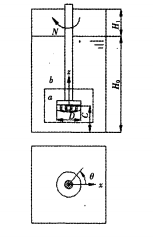
The structure of the rotary jet degassing unit used in the calculation is shown in Figure 1. The degassing unit is a square groove with a cross-sectional dimension of 468 mm X468 mm. The working medium in the tank is aluminum melt with density ρ L=2300 kg/m3, viscosity ρ L=0.0029 Pa·s, and the initial liquid level height H0 =650 mm. The rotating nozzle is located in the center of the degassing unit, the maximum outer diameter is D=160 mm, the clearance from the bottom is C=150 mm, and the stirring speed is N=300 r/m. Argon gas is sprayed into the aluminum melt from the nozzle holes on the rotating nozzle, with a flow rate of Q=0.28 m3/h and a density of ρ L= 1.6288 kg/m3, viscosity ρ L =2.125 x 10⁵ Pa·s, bubble diameter db = 1.0 mm. In order to facilitate the distinction, phase angle 9 is defined in this paper to represent the longitudinal sections at different positions, that is, the angle that each longitudinal section rotates counterclockwise relative to the tea axis with the z-axis as the rotation axis. Fig. 1 Schematic diagram of the structure of the rotary blowing degassing unit. In addition, different bottom clearances, bubble diameters, and degassing box forms are selected in this paper to investigate the influence of different parameters on the process of rotary blowing and degassing of aluminum melt.

2 CFD analysis of rotary jet degassing with nitrogen process
2.1 Mathematical model
The Euler model was used to simulate the two-phase flow field during the degassing process of aluminum melt by rotary blowing, so as to fully consider the bidirectional coupling between gas and liquid. The interphase drag force adopts the Schiller-Naumann model, and the dispersed k-8 two-phase turbulence model is selected to describe the turbulence. Since the rotary blowing degassing unit is usually square, the phase angle of the blades on the rotating nozzle relative to the degassing unit is different at different times, and the flow field presents an unsteady characteristic of periodic changes with time. For this reason, the multi-reference coordinate system method is selected. Describe the interaction between the rotating nozzle and the side walls of the degassing unit.
2.2 Selection of computational domain, mesh division, and phase designation Purification gas is blown into the aluminum melt from the nozzle holes on the rotating nozzle, which will inevitably cause changes in the height of the liquid level, and there will also be bubbles from the free liquid surface. escape. To simplify the boundary setting of the free surface, select the initial surface height day. and the height of the gas phase section above the initial liquid level, (day, = 230 mm) as the height of the entire computational domain, as shown in Figure 1. Due to the multi-reference coordinate system method, the computational domain needs to be divided into two sub-domains, the inner domain, and the outer domain. The inner domain contains the moving rotating nozzle, and the outer domain b contains the static degassing unit, see Figure 1. The inner and outer subdomains and the upper gas phase segment are meshed with unstructured tetrahedral elements respectively. In order to make the calculation more accurate, local mesh refinement is performed on important areas. The total number of units finally generated is about 140,000. Set the aluminum melt as the main phase and argon as the secondary phase. In order to simplify the problem and reduce the computational cost, the bubble size is set to be uniform regardless of the phenomenon of bubble condensation and fragmentation.
2.3 Boundary conditions, initial conditions, and solution parameters
Boundary conditions: the inner domain adopts a rotating reference system; the inner wall of the degassing unit, the rotating rod, the rotating nozzle, and other surfaces are defined as non-slip walls, and the standard wall function is used for processing; the introduction of argon gas determines the velocity value according to the gas flow, The velocity inlet boundary is used; the top surface is defined as the pressure outlet boundary condition, and the volume fraction of the gas phase is set to 1. Considering that the problem studied in this paper belongs to the gas-liquid two-phase flow, there is bidirectional coupling between the gas and liquid, and convergence is difficult. In order to reduce the convergence difficulty, it is treated as an unsteady problem. Correspondingly, the initial conditions are set as follows: the computational domain is divided into upper and lower regions with the initial liquid surface as the boundary. For the area below the initial liquid level, set the volume fraction of argon to 0; for the area above the initial liquid level, set the volume fraction of argon to 1.
Using FLUENT6.2 computational fluid dynamics software. The equations are discretized by the finite volume method, the coupling between pressure and velocity is by the coupled SIMPLE algorithm, and the momentum, volume fraction, and turbulent momentum are discretized by the first-order upwind difference scheme. The convergence criterion is that the residuals of all variables are lower than 10-3, and when the argon gas flowing into the computational domain and the argon gas escaping from the top surface reaches mass equilibrium, the calculation is considered to be over.


