

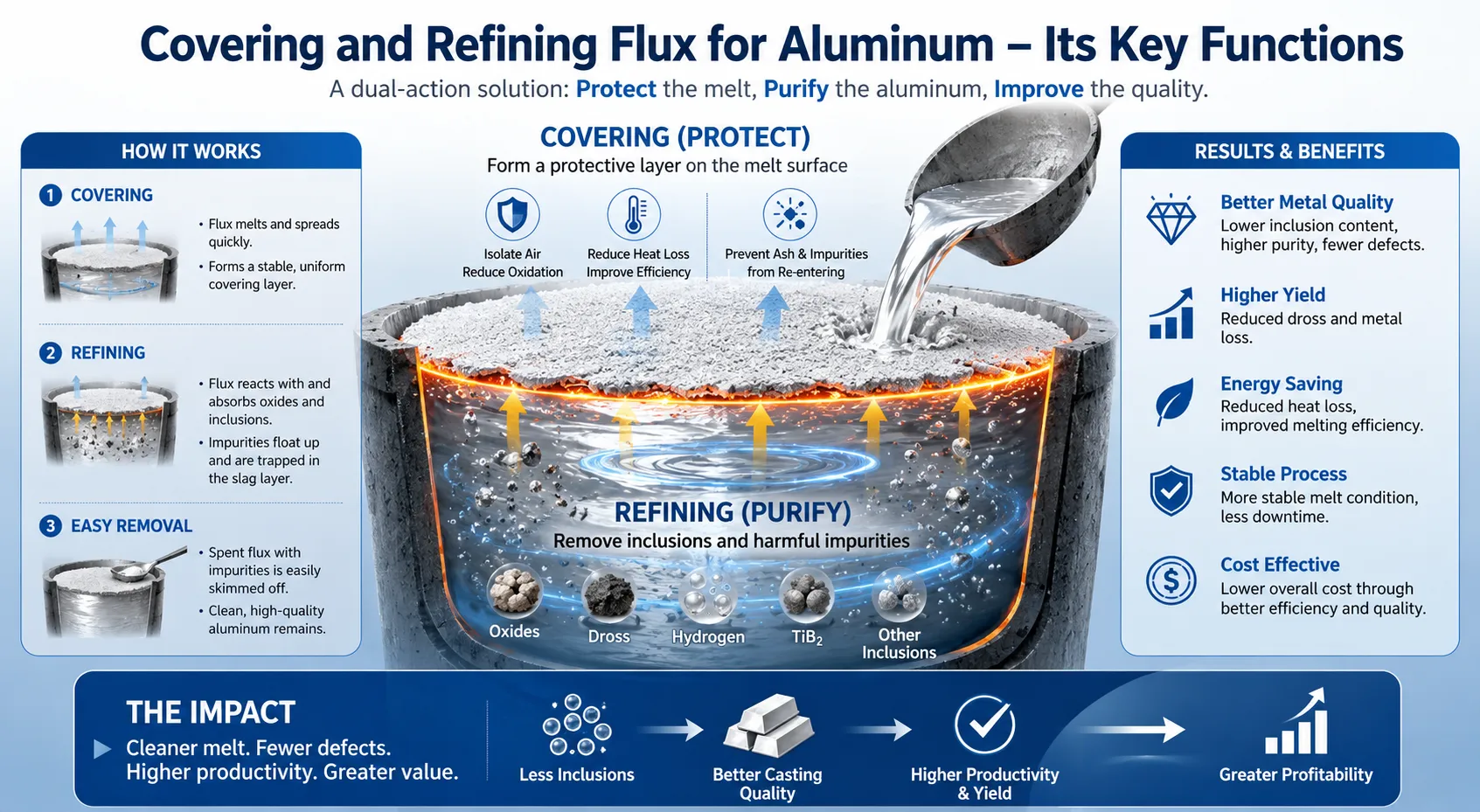
Cover flux for aluminium is a specially formulated mixture of inorganic salts applied directly to the surface of liquid aluminium in melting furnaces, holding furnaces, and ladles to create a physical and chemical barrier between the melt and the furnace atmosphere — and when correctly selected and applied, it measurably reduces metal oxidation losses by 40-70%, suppresses hydrogen absorption from atmospheric moisture, and significantly lowers the dross generation rate that drives both metal yield losses and downstream casting defects. After working with aluminium foundries, secondary smelters, and continuous casting operations across multiple continents, we can state clearly that cover flux is not a discretionary consumable — it is a fundamental process input that pays for itself many times over through reduced metal loss alone, before accounting for improvements in melt cleanliness and casting quality.
How Does Aluminium Oxidise in a Furnace? The Chemistry You Need to Understand
Why Liquid Aluminium Is So Prone to Surface Oxidation
Understanding why aluminium oxidises so aggressively in the molten state is the starting point for appreciating what cover flux actually does. Many engineers are surprised to learn that solid aluminium at room temperature is actually highly resistant to corrosion — the thin, self-healing oxide film that forms instantly on a freshly cut aluminium surface provides excellent protection. The problem in foundry operations is that the furnace environment attacks this protective layer in ways that do not occur at ambient temperatures.
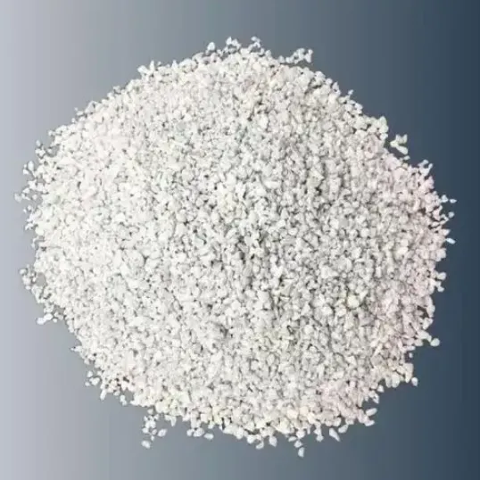
At liquid aluminium temperatures (660-850°C), several simultaneous reactions occur at the melt surface:
Primary oxidation reaction:
4Al + 3O₂ → 2Al₂O₃
This reaction is thermodynamically very favourable — aluminium has one of the highest affinities for oxygen of any common metal. The Gibbs free energy of formation of Al₂O₃ is approximately -1,676 kJ/mol at standard conditions, which means the driving force for oxidation is extremely strong at elevated temperatures.
Hydrogen absorption from moisture:
2Al + 3H₂O → Al₂O₃+ 6[H]
Atmospheric moisture reacts with the aluminium melt surface to simultaneously generate aluminium oxide and inject atomic hydrogen into the melt. This hydrogen then dissolves in the liquid aluminium and causes porosity during solidification. The rate of this reaction increases with atmospheric humidity, melt surface area, and melt temperature.
Magnesium oxidation (in Mg-containing alloys):
2Mg + O₂ → 2MgO
Mg + H₂O → MgO + H₂
Magnesium is even more reactive with oxygen and moisture than aluminium. In 5xxx, 6xxx, and 7xxx alloys containing significant magnesium, surface oxidation rates are dramatically higher, and the oxides formed (MgO and MgAl₂O₄ spinel) are more friable and harder to manage than pure Al₂O₃.
The dross formation cascade:
Once an aluminium oxide layer forms on the melt surface, it does not remain a thin, protective film at furnace temperatures. Unlike the solid-state passive film, the oxide at liquid aluminium temperatures is mechanically weak and is continuously disrupted by:
- Convection currents in the melt (buoyancy-driven and thermally driven flow)
- Charging of solid scrap or ingot onto the melt surface.
- Skimming, stirring, and melt transfer operations.
- Gas flames from burners impinging on the melt surface.
Each disruption of the surface oxide exposes fresh aluminium to oxidation, generating new oxide that incorporates metal droplets and forms a heterogeneous mixture of aluminium oxide and trapped liquid metal — this is dross. In an unprotected reverberatory furnace operating at 750°C, dross generation rates of 2-5% of melt weight per hour are not unusual under adverse conditions.
Oxidation rate as a function of temperature:
| Melt Temperature (°C) | Relative Oxidation Rate (Al only) | Relative Oxidation Rate (Al-5Mg) |
|---|---|---|
| 680 | 1.0 (baseline) | 4.2 |
| 700 | 1.3 | 5.8 |
| 720 | 1.7 | 7.5 |
| 750 | 2.4 | 11.2 |
| 780 | 3.3 | 16.8 |
| 800 | 4.1 | 22.4 |
| 850 | 6.8 | 38.0 |
The exponential increase in oxidation rate with temperature is a strong argument for minimising superheating beyond what casting requirements demand, and it demonstrates why cover flux becomes increasingly important at higher processing temperatures.
More Read: ما هو التدفق المستخدم للألومنيوم?
What Is Cover Flux Made Of? Chemical Composition and Salt Systems
The Key Chemical Components in Aluminium Cover Flux Formulations
Cover flux for aluminium is based on mixtures of inorganic chloride and fluoride salts, selected and blended to achieve a molten flux layer that covers the melt surface at aluminium processing temperatures. The flux must melt and spread at temperatures below the aluminium melt temperature to be effective, must wet the aluminium oxide surface without reacting destructively with the underlying metal, and must maintain its protective properties across the full duration of a melting or holding campaign.
Primary salt components and their functions:
Sodium chloride (NaCl) — common salt:
NaCl has a melting point of 801°C, which is above the typical aluminium processing temperature range. It is therefore not used alone but is combined with other salts to form eutectic mixtures with lower melting points. NaCl contributes low cost, good fluidity when molten, and serves as the base component of most flux formulations. Typical content in cover flux: 30-60%.
Potassium chloride (KCl):
KCl melts at 776°C and forms a eutectic with NaCl at approximately 657°C (the NaCl-KCl eutectic point). This binary eutectic is the foundation of the simplest cover flux systems. The NaCl-KCl eutectic is fluid and spreadable at aluminium processing temperatures, provides a reasonable surface seal, and wets aluminium oxide well. Typical content: 20-50%.
Sodium fluoride (NaF) and potassium fluoride (KF):
Fluoride salts are added to chloride base mixtures for two reasons: first, they lower the liquidus temperature of the flux mixture further, ensuring complete melting at lower temperatures; second, fluoride ions react with aluminium oxide at the flux-metal interface, helping to dissolve and incorporate surface oxides into the flux layer. This oxide dissolution improves the flux’s protective performance compared to chloride-only systems. Typical content: 5-20%.
الكريوليت (Na₃AlF₆F):
Cryolite is a natural or synthetic fluoride mineral used in some flux formulations as a source of both sodium and fluoride ions. It is particularly effective at dissolving aluminium oxide and is used in cleaning and drossing fluxes as well as cover formulations. However, cryolite generates significant fluoride emissions at aluminium processing temperatures, which raises workplace safety and environmental compliance concerns. Its use is decreasing in markets with strict fluoride emission regulations.
Magnesium chloride (MgCl₂):
MgCl₂ is hygroscopic (absorbs moisture from the air) and must be used carefully. However, in controlled amounts, it contributes to lowering the flux melting point and improves wetting on magnesium-containing alloy surfaces. Some cover flux formulations for high-magnesium alloys incorporate MgCl₂ at 5-15%.
Calcium fluoride (CaF₂) — fluorspar:
CaF₂ raises the viscosity of the molten flux, which can be advantageous for preventing flux from flowing off the melt surface in tilting or turbulent operations. It also contributes fluoride activity for oxide dissolution. Typical content: 0-15%.
Standard cover flux composition ranges:
| المكوّن | Low-Fluoride Formulation (%) | Standard Formulation (%) | High-Mg Alloy Formulation (%) |
|---|---|---|---|
| كلوريد الصوديوم | 45 – 60 | 35 – 50 | 25 – 40 |
| كلوريد الكالسيوم | 30 - 45 | 25 – 40 | 20 – 35 |
| ناف | 2 – 8 | 5 – 12 | 8 – 15 |
| ك. ف. ف | 0 - 5 | 3 – 10 | 5 – 12 |
| CaF₂ | 0 – 3 | 2 – 8 | 3 – 10 |
| MgCl₂ | 0 | 0 - 5 | 5 – 15 |
| نا₃AlF₆F₆ | 0 | 0 - 5 | 0 – 8 |
Melting point of flux mixture:
The target melting point for a cover flux intended for aluminium is 550-650°C — well below the aluminium liquidus of 660°C. This ensures that the flux melts and flows into a continuous layer before the aluminium metal temperature rises to full processing temperature. A flux that melts above the aluminium processing temperature will not spread effectively and will leave unprotected areas of melt surface.
Types of Aluminium Fluxes and How Cover Flux Differs from Cleaning and Refining Flux
Understanding the Full Aluminium Flux Family
The term “aluminium flux” is used loosely in the foundry industry to refer to several chemically and functionally distinct products. Purchasing the wrong flux type for your application is a common and costly mistake.
Cover flux (protective flux):
Primary function: create a continuous molten salt barrier on the melt surface that prevents atmospheric oxygen and moisture from contacting the liquid aluminium. Secondary function: prevent heat loss from the melt surface (acts as a thermal insulation layer). Does not significantly alter melt composition or aggressively attack oxide inclusions within the melt body. Applied continuously at low dosage rates throughout the melting and holding period.
Cleaning flux (drossing flux):
Primary function: remove oxide inclusions and dross from the melt by incorporating them into the flux phase. Cleaning fluxes are typically higher in fluoride content than cover fluxes and are more chemically aggressive. They are applied periodically — not continuously — to treat accumulated dross and draw inclusions out of the melt. After treatment, the flux-dross mixture is skimmed off, taking captured inclusions with it.
Refining flux:
Primary function: remove specific impurities from the melt, typically magnesium (in alloys where Mg has been contaminated to above-specification levels) or sodium (which causes embrittlement in some alloys). Refining fluxes contain reactive components that selectively combine with the target impurity. They are used intermittently as a corrective treatment.
Degassing flux (tablet or powder):
Primary function: generate bubbles of reactive gas within the melt to carry dissolved hydrogen to the surface. These fluxes release chlorine gas (from chlorine-generating compounds such as hexachloroethane) or other reactive gases when immersed in liquid aluminium. They are less effective than rotary argon degassing but are used in smaller operations or as a supplement.
Grain refining flux:
Primary function: introduce titanium and boron into the melt to provide heterogeneous nucleation sites during solidification. These fluxes contain potassium titanium fluoride (K₂TiF₆) and potassium boron fluoride (KBF₄) in controlled ratios.
Flux function comparison table:
| نوع التدفق | توقيت التطبيق | طريقة التطبيق | Primary Benefit | مستوى الفلورايد |
|---|---|---|---|---|
| تدفق الغطاء | Continuous / frequent | الانتشار السطحي | الوقاية من الأكسدة | منخفضة إلى متوسطة |
| تدفق التنظيف | Periodic (per heat or campaign) | Stirred into melt | Dross removal, cleanliness | متوسط إلى مرتفع |
| تكرير التدفق | Corrective, as needed | Stirred into melt | Composition adjustment | متغير |
| تدفق التفريغ الغازي | Per heat, before casting | Submerged tablet/plunger | إزالة الهيدروجين | منخفضة |
| Grain refining flux | Per heat, timed addition | Wire or plunger addition | تنقية بنية الحبيبات | عالية |
In practice, a well-run aluminium foundry uses cover flux throughout the melting and holding period and supplements with periodic cleaning flux treatment before skimming. Degassing is typically handled by a rotary unit rather than flux tablets in modern operations. Understanding this distinction is critical when comparing prices between flux types — a supplier quoting a low price for a cleaning flux that is being requested as a cover flux will create operational problems.
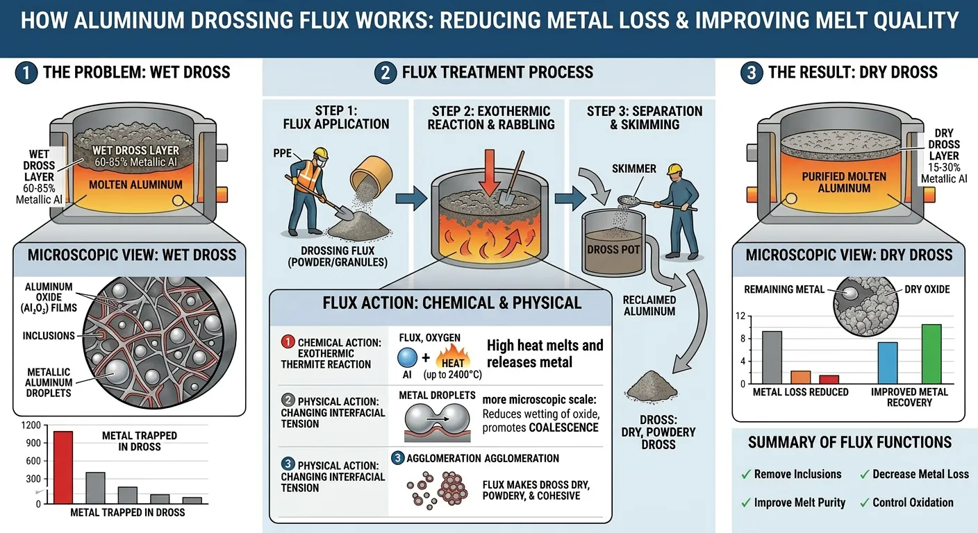
How Cover Flux Works: Physical Barrier vs. Chemical Protection Mechanisms
The Two Layers of Protection That Cover Flux Provides
Cover flux protects liquid aluminium through two mechanisms operating simultaneously, and the relative contribution of each mechanism depends on the flux composition, application rate, and operating conditions.
Mechanism 1: Physical barrier protection
When cover flux is applied to the melt surface and melts to form a continuous molten salt layer, it physically separates the liquid aluminium from the furnace atmosphere. Oxygen, nitrogen, water vapour, and combustion products from gas burners cannot reach the aluminium surface through a continuous flux layer. This is the simplest and most intuitive protection mechanism.
The effectiveness of physical barrier protection depends entirely on coverage continuity. A flux layer with gaps — caused by insufficient dosage, localised evaporation of low-boiling components, or mechanical disruption from stirring — provides proportionally less protection. The barrier must cover the entire melt surface continuously, including corners and edges where oxidation often concentrates.
The flux layer also acts as a thermal insulator between the melt and the furnace atmosphere, reducing the temperature gradient at the melt surface and thereby slowing natural convection currents that would otherwise continuously expose fresh aluminium to the atmosphere.
Mechanism 2: Chemical oxide dissolution and absorption
The fluoride components in cover flux actively react with aluminium oxide inclusions that form at the flux-metal interface:
Al₂O₃ + 6NaF → 2AlF₃ + 3Na₂O
Al₂O₃ + Na₃AlF₆ → 4AlF₃ + 3NaO (simplified)
These reactions dissolve Al₂O₃ into the flux phase, preventing the accumulation of a coherent oxide layer at the interface that would otherwise trap metal droplets and form dross. By continuously dissolving nascent oxide as it forms, a fluoride-containing cover flux keeps the melt-flux interface clean and maintains good contact between the protective salt layer and the fresh aluminium surface.
This chemical dissolution mechanism is why fluoride-free or very-low-fluoride cover fluxes — despite providing physical barrier protection — are less effective at controlling dross formation than properly formulated fluoride-containing fluxes. The physical barrier alone prevents oxygen from reaching the melt, but it does not address the oxide that forms from oxygen absorbed before the flux layer is established, or from oxide films introduced with scrap charges.
Protection efficiency by mechanism:
| حالة التشغيل | Physical Barrier Contribution | Chemical Dissolution Contribution | Combined Protection |
|---|---|---|---|
| Clean melt, no scrap charging | 70% | 30% | ممتاز |
| Active scrap charging | 45% | 55% | جيد |
| High-humidity environment | 50% | 50% | جيد |
| High-magnesium alloy | 30% | 70% | Moderate (requires high-Mg formulation) |
| Turbulent melt (stirring) | 35% | 65% | Moderate (requires higher dosage) |
| Long holding periods | 65% | 35% | جيد |
Cover Flux Application Methods: Powder, Granule, and Tablet Forms Compared
Which Physical Form of Cover Flux Is Best for Your Operation?
Cover flux is commercially available in three physical forms — powder, granule, and pressed tablet — each with distinct advantages and limitations that affect both performance and ease of application.
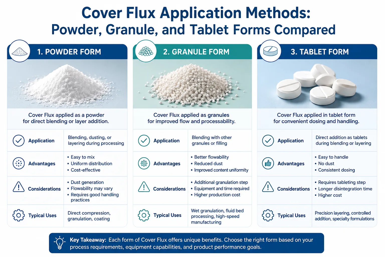
Powder form (particle size 0.1 – 1.0 mm):
Powdered cover flux spreads most easily over the melt surface and melts fastest to form a continuous layer due to its high surface-area-to-volume ratio. It can be applied manually using a sieve or shovel, or through automated pneumatic dispensing systems. The disadvantages of powder are significant: dust generation during handling creates respiratory hazards and flux losses before the material even reaches the melt; powder can be easily blown by furnace drafts before it melts into place; and storage requires careful moisture protection since the hygroscopic salts absorb atmospheric humidity readily.
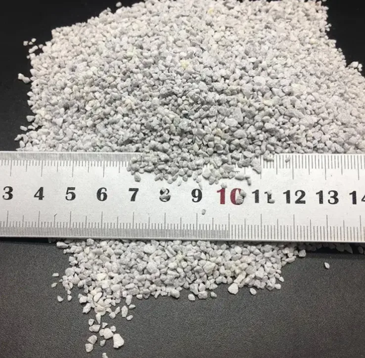
Granule form (particle size 1.0 – 5.0 mm):
Granular cover flux represents the best balance of performance and handling practicality for most foundry environments. The larger particle size reduces dust generation during handling while still providing rapid melting and spreading on the melt surface. Granules are less susceptible to wind displacement before melting and flow freely from standard scoops and dispensing equipment. This is the form we most frequently recommend for manual application in foundry operations.
Pressed tablet form (20 – 100g per tablet):
Tablets are produced by compressing powdered flux under high pressure without binders. They offer the cleanest handling characteristics — minimal dust, no spillage, easy counting for precise dosage control — and are well suited to automated addition systems where tablets are dropped onto the melt surface at controlled intervals. The tradeoff is slower initial melting compared to powder or granule due to the lower surface area, which can leave the melt surface partially unprotected during the melt-in period if tablets are placed infrequently. Tablets are commonly used in holding furnaces where the melt surface is stable and infrequent additions are acceptable.
Physical form comparison:
| الممتلكات | المسحوق | Granule | Tablet |
|---|---|---|---|
| Melting speed | سريع | معتدل | بطيء |
| توليد الغبار | عالية | منخفضة | منخفضة جداً |
| Handling safety | Requires PPE | Standard PPE | سهولة |
| Dosage precision | منخفضة | معتدل | عالية |
| حساسية الرطوبة | عالية جداً | عالية | معتدل |
| Automated application | Possible (pneumatic) | Possible | ممتاز |
| Coverage uniformity | ممتاز | جيد | معتدل |
| Storage requirement | Sealed, dry | Sealed, dry | Sealed, dry |
| أفضل تطبيق | Static furnaces, automated | Manual foundry use | Holding furnaces, automation |
Application Equipment for Cover Flux
Manual application uses simple handheld sieves or perforated scoops that allow even distribution over the melt surface. The operator should apply flux from the furnace door or charging area, distributing it across the entire melt surface including corners and edges — not simply dumping it in a pile at one location.
Automated flux addition systems use either pneumatic conveying (for powder and fine granule) or mechanical feeders (for granule and tablet) to deliver controlled quantities of flux to the melt surface at preset intervals. These systems reduce labour cost, improve dosage consistency, and reduce dust exposure for furnace operators. They are cost-effective for operations running multiple shifts or where high flux consumption makes manual dosing labour-intensive.
Dosage Rates and Application Frequency by Furnace Type
How Much Cover Flux Should You Apply and How Often?
Dosage rate is the most frequently misapplied aspect of cover flux use. Underdosing leaves areas of the melt surface unprotected and fails to suppress dross formation. Overdosing wastes flux, increases dross volume (the excess flux becomes part of the dross layer), and can introduce excess fluoride into the melt if the flux is excessively stirred.
The correct dosage targets a continuous, self-levelling layer 5-15mm thick across the entire melt surface. This layer should appear smooth and molten at operating temperature, with no dry, unmelted patches, and no large accumulations that have become thick, viscous, and difficult to skim.
Recommended cover flux dosage rates:
| نوع الفرن | Initial Charge Dosage (kg/tonne Al) | Maintenance Dosage (kg/tonne Al per hour) | Application Frequency |
|---|---|---|---|
| Gas-fired reverberatory | 2.0 – 4.0 | 0.5 – 1.5 | Every 30-60 minutes |
| Electric resistance furnace | 1.0 – 2.5 | 0.3 - 0.8 | Every 60-90 minutes |
| Induction furnace (coreless) | 1.5 – 3.0 | 0.4 - 1.0 | Every 45-75 minutes |
| Crucible furnace (gas) | 1.5 – 3.0 | 0.5 – 1.2 | Every 30-60 minutes |
| فرن الحجز | 0.5 – 1.5 | 0.2 – 0.5 | Every 60-120 minutes |
| Ladle (transfer, short duration) | 1.0 – 2.0 | غير متاح | At start of transfer |
Factors that increase required dosage:
- High-humidity foundry environment (more moisture to exclude)
- High-magnesium alloy composition (faster oxidation rate)
- Elevated melt temperature (above 750°C)
- Frequent scrap charging that disrupts the flux layer.
- Burner flame impingement on melt surface (combustion gases attack flux layer)
- Long holding times between casting operations.
Factors that allow reduced dosage:
- Electric furnace (no combustion atmosphere over the melt)
- Low-humidity environment or air-conditioned facility
- Inert atmosphere furnace (argon or nitrogen blanket over melt)
- Clean, dry scrap charges requiring minimal melt-in.
- Short holding times between ladle fillings.
Cover Flux Selection by Alloy Type: Why One Formula Does Not Suit All Alloys
Matching Cover Flux Chemistry to Aluminium Alloy Composition
The oxidation behaviour of aluminium changes significantly with alloy composition, and a cover flux formulation optimised for pure aluminium or low-alloy material may perform poorly on high-magnesium or high-zinc alloys. This is an area where we see significant losses in foundry operations that use a single flux formulation across their entire alloy range.
Pure aluminium and 1xxx series:
These alloys have the simplest oxidation chemistry — primarily Al₂O₃ formation. Standard NaCl-KCl based cover flux with moderate fluoride content (8-15% total fluoride) performs well. Low-fluoride formulations are acceptable where emissions are a regulatory concern.
2xxx series (Al-Cu alloys):
Copper does not contribute significantly to melt surface oxidation. Standard cover flux formulations appropriate for 1xxx alloys are suitable. The higher processing temperatures typical for 2xxx alloys (730-760°C) mean slightly higher dosage rates may be required.
3xxx series (Al-Mn alloys):
Manganese forms manganese oxides at the melt surface, but at lower concentrations these are incorporated into the primary Al₂O₃ layer. Standard cover flux is appropriate. No special formulation adjustment needed.
4xxx series (Al-Si alloys, including casting alloys A356, A380, A413):
Silicon does not oxidise preferentially at the melt surface — the aluminium still dominates surface oxidation chemistry. Standard cover flux formulations work well for 4xxx wrought alloys and most casting alloys in this family. However, some high-Si casting alloys processed at lower temperatures benefit from lower-melting-point flux formulations that provide full coverage at 700°C or below.
5xxx series (Al-Mg alloys, 2-6% Mg):
This is where flux selection becomes critical. Magnesium oxidises approximately 1,000 times faster than aluminium at 750°C and generates MgO and MgAl₂O₄ spinel, which are less dense and more voluminous than Al₂O₃. The standard NaCl-KCl flux system provides inadequate protection for 5xxx alloys because the fluoride content needed to dissolve MgO and spinel is substantially higher than what is needed for Al₂O₃. Dedicated high-magnesium cover flux formulations with 15-25% total fluoride content are required. These formulations also typically include BaCl₂ or CaCl₂ additions that improve wetting on the higher-reactivity alloy surface.
6xxx series (Al-Mg-Si alloys, 0.2-1.2% Mg):
Lower magnesium content than 5xxx, so standard cover flux with moderate fluoride content is generally adequate. For 6xxx alloys at the higher end of the Mg range (above 0.8%), it is worth using a flux with slightly elevated fluoride content or applying at a higher dosage rate.
7xxx series (Al-Zn-Mg alloys, up to 3% Mg):
The combination of zinc and magnesium creates a challenging oxidation environment. Both elements oxidise readily, and zinc oxide (ZnO) adds to the dross complexity. High-fluoride cover flux formulations similar to those used for 5xxx alloys are appropriate, with dosage rates at the upper end of the recommended range.
Flux formulation recommendation by alloy family:
| سلسلة السبائك | Mg Content (%) | نوع التدفق الموصى به | Total Fluoride Target (%) | Dosage Adjustment vs. Standard |
|---|---|---|---|---|
| 1xxx | < 0.05 | Standard cover flux | 8 – 12 | خط الأساس |
| 2xxx | < 0.05 | Standard cover flux | 8 – 12 | +10% for higher temp |
| 3xxx | < 0.05 | Standard cover flux | 8 – 12 | خط الأساس |
| 4xxx casting | < 0.10 | Standard or low-temp flux | 8 – 15 | Baseline to +10% |
| 5xxx (2-4% Mg) | 2.0 – 4.0 | High-Mg cover flux | 15 – 20 | +30 – 50% |
| 5xxx (4-6% Mg) | 4.0 – 6.0 | Premium high-Mg flux | 20 – 28 | +50 – 75% |
| 6xxx | 0.2 – 1.2 | Standard or mid-fluoride | 10 – 16 | +10 – 20% |
| 7xxx | 1.0 - 3.0 | High-Mg / high-fluoride | 16 – 24 | +30 – 50% |
How Cover Flux Affects Dross Formation and Metal Recovery
The Direct Relationship Between Cover Flux Quality and Metal Yield
Dross is the most visible consequence of poor cover flux performance. Every kilogram of dross generated represents both direct metal loss (dross typically contains 40-80% entrapped aluminium metal, depending on how it is managed) and indirect costs — labour for skimming, dross processing or disposal, and downstream quality problems from dross particles contaminating the melt.
The financial impact of dross generation is substantial. In a foundry melting 10 tonnes of aluminium per day with a dross rate of 3% (300 kg dross per day) and a metal recovery from dross of 60%, the gross daily metal loss from dross is 120 kg of aluminium. At current aluminium prices, this represents a significant daily cost that accumulates quickly over a month or year of operation.
Cover flux impact on dross generation:
The primary mechanism by which cover flux reduces dross is continuous suppression of the oxide formation rate at the melt surface. Less oxide formation means less material to entrap metal droplets, less dross volume generated, and higher metal recovery from the dross that does form.
Studies conducted across multiple foundry operations consistently show:
- Operations without cover flux: dross rate 3-6% of melt weight.
- Operations with standard cover flux at correct dosage: dross rate 1.5-3% of melt weight.
- Operations with optimal cover flux formulation and dosage: dross rate 0.8-1.8% of melt weight.
Additionally, dross formed under a protective flux layer has higher metal content and is easier to recover than dross formed on an unprotected melt surface. Under-flux dross tends to be a dry, crumbly mixture with 40-55% metal content. Well-formed dross from a properly fluxed operation is a wetter, more fluid material with 60-80% metal content that can be more efficiently processed in a dross press or rotary salt furnace.
Dross generation comparison by cover flux practice:
| Cover Flux Practice | Dross Rate (% of melt wt.) | Metal in Dross (%) | Net Metal Loss (%) | Cost Impact vs. No Flux |
|---|---|---|---|---|
| No cover flux | 4.5 – 6.0 | 40 – 55 | 2.2 – 3.3 | Baseline (highest cost) |
| Incorrect flux type | 3.5 – 5.0 | 45 – 60 | 1.8 – 2.8 | -15 to -20% |
| Underdosed standard flux | 2.5 – 4.0 | 50 - 65 | 1.2 – 2.0 | -30 to -40% |
| Optimal standard flux | 1.5 – 2.5 | 60 – 75 | 0.6 – 1.0 | -55 to -70% |
| Optimal high-Mg flux (5xxx) | 1.8 – 3.0 | 62 – 78 | 0.7 – 1.2 | -50 to -65% |
Environmental and Safety Considerations: Fluoride Content and Workplace Exposure
Managing Fluoride Emissions and Worker Safety in Flux Operations
Fluoride-containing cover fluxes generate gaseous fluoride compounds during operation — primarily hydrogen fluoride (HF) and silicon tetrafluoride (SiF₄) from reactions between fluoride salts and silica-containing materials. These emissions require careful management to protect worker health and meet environmental regulations.
Hydrogen fluoride (HF) exposure limits:
| الهيئة التنظيمية | HF Exposure Limit | Time Basis |
|---|---|---|
| OSHA (USA) | 3 ppm | 8-hour TWA |
| ACGIH (USA) | 0.5 جزء في المليون | Ceiling (instantaneous) |
| EU (EH40) | 1 جزء في المليون | 8-hour TWA |
| UK HSE (WEL) | 1 جزء في المليون | 8-hour TWA |
At typical aluminium foundry flux application rates, HF concentrations at the furnace operator position can reach 1-5 ppm without ventilation controls — potentially exceeding regulatory limits depending on jurisdiction.
Engineering controls for fluoride emission management:
Local exhaust ventilation (LEV) installed directly above or alongside the furnace opening is the primary control measure. The LEV system captures fluoride-containing gases at the generation point before they disperse into the working environment. Requirements include:
- Capture velocity at the furnace opening: minimum 0.5-1.0 m/s.
- Exhaust volume: calculated based on furnace opening area and operating temperature.
- Treatment of exhaust gases: wet scrubbing (sodium hydroxide solution) or dry lime injection before atmospheric discharge.
- Regular monitoring of airborne HF concentrations at operator positions.
Personal protective equipment (PPE) for flux handling:
| المهمة | معدات الوقاية الشخصية المطلوبة |
|---|---|
| Flux storage and handling | Nitrile gloves, dust mask (P2/FFP2), safety glasses |
| Flux application to melt | Heat-resistant gloves, face shield, dust mask, protective clothing |
| Skimming fluxed dross | Face shield, heat-resistant gloves and sleeves, respiratory protection |
| Working near furnace during flux operation | Supplied air respirator recommended in high-fluoride environments |
Low-fluoride and fluoride-free flux alternatives:
Growing regulatory pressure on fluoride emissions has driven development of reduced-fluoride and fluoride-free cover flux formulations. These products substitute borate compounds, phosphate additions, and specialised organic carriers for some or all of the fluoride content. The tradeoff is typically reduced oxide dissolution performance — physical barrier protection is maintained, but chemical dissolution of forming oxide is less effective. For low-to-moderate risk operations (pure aluminium, low-Mg alloys, clean melts), low-fluoride fluxes can provide adequate protection with substantially reduced HF emissions.
Quality Indicators: How to Evaluate Cover Flux Before and During Use
What to Check When Qualifying a Cover Flux Supplier
Cover flux quality varies considerably between suppliers, and purchasing based on price alone without specification verification frequently leads to operational problems that cost far more than the price difference saved. We have audited several foundry operations where substandard flux purchased at a 15-20% discount resulted in dross rates double those achievable with a quality product — the financial loss from excess dross far exceeded the flux cost savings.
Key quality parameters to specify and verify:
| المعلمة | ما أهمية ذلك | طريقة الاختبار | المواصفات النموذجية |
|---|---|---|---|
| التركيب الكيميائي | Incorrect NaCl/KCl/fluoride ratio affects melting point and performance | XRF or wet chemical analysis | Per formulation specification |
| Melting point / liquidus | Flux must melt below aluminium processing temperature | DSC (Differential Scanning Calorimetry) | 550 – 650°C |
| محتوى الرطوبة | Moisture releases steam on contact with melt, causing spattering and hydrogen pickup | معايرة كارل فيشر | < 0.5% by weight |
| توزيع حجم الجسيمات | Affects melting speed and dust generation | تحليل المنخل | Per agreed specification |
| الكثافة السائبة | Affects dosage by volume vs. weight | Tap density measurement | Per agreed specification |
| Fluoride content (total) | Determines oxide dissolution capability and emission potential | قطب كهربائي انتقائي أيوني | Per formulation specification |
| Heavy metal impurities | Lead, cadmium, mercury must be absent in food-contact or sensitive applications | ICP-OES analysis | أقل من الحدود التنظيمية |
In-use quality assessment:
The most practical quality check during production is observation of the flux behaviour on the melt surface:
- Good quality flux: melts rapidly and smoothly, spreads uniformly across the melt surface, forms a continuous molten layer with a slightly oily or glassy appearance, remains fluid at operating temperature without excessive thickening.
- Poor quality flux: melts unevenly, leaves dry patches, forms a thick, pasty layer that does not spread, produces excessive fumes on contact with melt, or causes spattering (indicating moisture contamination).
Moisture contamination is the most common quality problem with chloride-based fluxes. Even flux that left the factory with acceptable moisture content can absorb significant atmospheric moisture during shipping and storage. Flux stored in damaged or partially opened bags in a humid warehouse for several weeks can reach moisture contents above 2-3%, which causes violent steam release and spattering when applied to a melt at 720-750°C — a significant safety hazard. Always store flux in sealed, undamaged bags in a dry area, and consider purchasing in smaller bag sizes if usage rate is low.
Cover Flux for High-Magnesium Alloys: Special Formulation Requirements
Why Standard Cover Flux Fails on 5xxx and 7xxx Series Aluminium
High-magnesium aluminium alloys present the most challenging cover flux application in the foundry industry. The failure mode is specific and consistent: an operator who has successfully used a standard NaCl-KCl flux on 1xxx or 4xxx alloys switches to 5xxx alloy production without changing the flux formulation, and observes dramatically increased dross formation, frequent surface fires (burning of the magnesium-rich dross in air), and deteriorating melt quality.
The root cause is that standard cover flux has inadequate fluoride content to dissolve and incorporate MgO and MgAl₂O₄ spinel as these form at the melt surface. Without effective oxide dissolution, the oxide layer thickens, entraps metal, and eventually burns in the furnace atmosphere — generating additional oxide and heat in a self-sustaining reaction.
Requirements for a cover flux suitable for high-magnesium alloys:
Higher total fluoride content (18-28%): Sufficient fluoride activity to continuously dissolve MgO and spinel as they form, preventing accumulation of a reactive oxide layer.
Modified base salt system: Some high-Mg flux formulations incorporate BaCl₂ (barium chloride) or CaCl₂ (calcium chloride) at 5-15% to improve wetting characteristics on the magnesium-rich surface and to increase the density of the molten flux layer (better coverage under turbulent conditions).
Controlled viscosity: The molten flux must remain fluid enough to flow into surface disruptions caused by convection currents but viscous enough not to slide off the surface during charging operations. High-Mg flux formulations balance these requirements through careful CaF₂ content adjustment.
Higher application rate: Due to the faster oxidation rate of Mg-containing alloys, dosage rates for high-Mg cover flux are typically 30-75% higher than for equivalent standard cover flux applications.
Suppression of burning reactions: Some specialised formulations include small additions of inhibiting compounds (borates or specialised proprietary additives) that elevate the ignition temperature of the dross surface, preventing the surface burning events that cause rapid metal loss in high-Mg alloy melts.
Cost-Benefit Analysis: Calculating the Return from Cover Flux Use
Quantifying the Financial Case for Cover Flux Investment
The economic justification for cover flux use is straightforward to calculate once you know your current dross generation rate and aluminium price. Here is a worked example based on a medium-sized aluminium foundry:
Baseline operation (no cover flux):
- Daily melt throughput: 8 tonnes aluminium
- Dross generation rate: 4.5% (360 kg dross per day)
- Metal content in dross: 50% (180 kg recoverable metal per day, 180 kg lost)
- Current aluminium price: $2,400 per tonne
- Daily metal loss value: 180 kg × $2.40 = $432 per day
- Annual metal loss value: $432 × 300 working days = $129,600
With optimised cover flux application:
- Cover flux dosage: 2.5 kg per tonne = 20 kg per day
- Cover flux cost: $2.50 per kg = $50 per day
- New dross generation rate: 1.8% (144 kg dross per day)
- Metal content in dross: 68% (97.9 kg recoverable, 46 kg lost)
- Daily metal loss value: 46 kg × $2.40 = $110 per day
- Annual metal loss value: $110 × 300 = $33,000
Net annual saving:
- Metal loss reduction: $129,600 – $33,000 = $96,600
- Annual flux cost: $50 × 300 = $15,000
- Net annual saving: $96,600 – $15,000 = $81,600
- Return on flux investment: 544%
This calculation is conservative — it excludes savings from reduced skimming labour, improved casting quality (lower scrap rates), reduced furnace maintenance (less oxide buildup on furnace walls), and improved consistency of alloy composition.
Sensitivity analysis — net saving at different metal prices:
| Aluminium Price ($/tonne) | Daily Metal Loss Saving ($) | Annual Net Saving ($) | ROI on Flux Cost |
|---|---|---|---|
| $1,800 | $240 | $57,000 | 380% |
| $2,200 | $310 | $72,000 | 480% |
| $2,400 | $322 | $81,600 | 544% |
| $2,800 | $385 | $100,500 | 670% |
| $3,200 | $450 | $120,000 | 800% |
Across any realistic aluminium price range, the return on cover flux investment is highly positive. The economic case is strongest at higher metal prices, but even at historically low aluminium prices, cover flux use returns multiple times its cost in metal yield improvement alone.
الأسئلة الشائعة
Q1: What is cover flux for aluminium and what does it do?
Cover flux is a mixture of inorganic salts — primarily sodium chloride, potassium chloride, and fluoride compounds — applied to the surface of liquid aluminium in a furnace or ladle. It creates a molten salt barrier that physically separates the aluminium melt from the furnace atmosphere, preventing oxidation by atmospheric oxygen and moisture. The fluoride components in the flux also chemically dissolve aluminium oxide as it forms at the melt surface, suppressing dross generation. The result is lower metal loss, cleaner melt, and reduced downstream casting defects.
Q2: How do you apply cover flux to liquid aluminium?
Cover flux is applied by distributing the material evenly across the entire melt surface — including corners and edges — using a sieve, perforated scoop, or automated dispensing system. An initial charge of 2-4 kg per tonne of aluminium establishes the protective layer. Subsequent maintenance additions of 0.5-1.5 kg per tonne per hour are made at regular intervals (every 30-90 minutes depending on furnace type) to compensate for flux consumed or skimmed with dross. The flux must cover the complete melt surface continuously — bare areas are not protected.
Q3: What is the difference between cover flux and drossing flux?
Cover flux is applied continuously at low dosage rates to protect the melt surface from oxidation throughout the melting and holding period. Drossing flux (cleaning flux) is applied periodically at higher dosage rates and stirred into the melt or dross to incorporate oxide inclusions into the flux phase for removal. Cover flux prevents dross from forming; drossing flux helps remove dross that has already formed. The two products have different chemical compositions — drossing fluxes are typically higher in fluoride content and more chemically aggressive.
Q4: How much cover flux should I use per tonne of aluminium?
The recommended initial dosage is 2-4 kg of cover flux per tonne of aluminium, with maintenance additions of 0.5-1.5 kg per tonne per hour. Exact dosage depends on furnace type, alloy composition, melt temperature, and environmental humidity. High-magnesium alloys (5xxx, 7xxx series) require 30-75% higher dosage rates than standard alloys due to their higher oxidation rate. Electric furnaces require lower dosage than gas-fired furnaces because there is no combustion atmosphere above the melt.
Q5: Can I use cover flux on all aluminium alloys?
Standard cover flux formulations (NaCl-KCl with 8-15% fluoride) are suitable for most aluminium alloys with low magnesium content — 1xxx, 2xxx, 3xxx, 4xxx casting alloys, and lower-Mg 6xxx alloys. High-magnesium alloys (5xxx series above 2% Mg, 7xxx series, and high-Mg 6xxx alloys) require specially formulated high-magnesium cover flux with higher fluoride content (15-28%) to effectively dissolve MgO and spinel inclusions. Using a standard flux on high-Mg alloys results in inadequate protection, excessive dross, and potentially dangerous surface burning reactions.
Q6: Is cover flux hazardous to use? What safety precautions are needed?
Cover flux contains chloride and fluoride salts that generate hydrogen fluoride (HF) gas when heated in contact with moisture or when in contact with liquid aluminium. HF is a toxic gas with a regulatory exposure limit of 0.5-3 ppm depending on jurisdiction. Foundry operators applying or working near cover flux should wear appropriate PPE including heat-resistant gloves, face shields, and respiratory protection. Local exhaust ventilation should be installed above furnace openings to capture emissions. Flux should be stored in sealed bags in a dry location to prevent moisture absorption that worsens HF generation.
Q7: Why is my aluminium melt producing excessive dross even with cover flux?
Excessive dross despite cover flux use typically indicates one or more of the following problems: incorrect flux formulation for the alloy being processed (particularly if processing high-Mg alloys with standard flux); insufficient dosage or application frequency leaving areas of melt surface unprotected; moisture-contaminated flux that is partially decomposing before providing protection; melt temperature too high for the operating conditions; mechanical disruption of the flux layer from scrap charging or excessive stirring without subsequent flux replenishment; or burner flames impinging directly on the melt surface and burning through the flux layer.
Q8: How should cover flux be stored to maintain its quality?
Store cover flux in its original, sealed packaging in a clean, dry indoor location away from moisture sources. Chloride-fluoride salt mixtures are hygroscopic — they absorb moisture from the air, which degrades their performance and creates a safety hazard (moisture in flux causes spattering and HF generation when the flux contacts liquid aluminium). Bags that have been opened and only partially used should be resealed immediately with tape or clips. Avoid storing flux near water pipes, outdoor areas, or humid environments. First-in, first-out stock rotation ensures older material is used before moisture absorption becomes significant.
Q9: Does cover flux affect the chemical composition of the aluminium melt?
Correctly applied cover flux at recommended dosage rates has minimal effect on aluminium melt composition. Small amounts of sodium from NaCl/NaF can dissolve into the melt — sodium embrittlement is a concern in some 6xxx and 7xxx alloys. This is managed by using potassium-based flux formulations where sodium pickup is critical, or by limiting contact time between the flux and the melt at operating temperature. Fluoride contamination of the melt is negligible at correct dosage rates. Flux that is stirred into the melt (rather than resting on the surface) significantly increases the risk of compositional contamination and should be avoided except for deliberate cleaning flux treatments.
Q10: What is the environmental impact of aluminium cover flux disposal?
Used cover flux mixed with dross contains chloride and fluoride salts that are classified as hazardous waste in many jurisdictions due to leaching potential. The salt-rich dross fraction generated from fluxed operations should be processed through a dross press to recover trapped metal and then the salt cake should be sent to a licensed processing facility. Modern secondary aluminium facilities use closed-loop salt recovery systems where the salt cake is reprocessed in rotary salt furnaces, recovering additional metal and regenerating the salt for reuse. Direct landfill disposal of flux-containing salt cake is prohibited or heavily regulated in the EU, North America, and many other regions.
Conclusion: Choosing the Right Cover Flux for Your Aluminium Foundry
Cover flux for aluminium is a small-cost, high-impact consumable that sits at the intersection of metal yield, melt quality, and operational safety. The correct selection and application of cover flux consistently delivers a return of 400-800% on consumable cost through reduced metal loss alone, before accounting for downstream quality improvements.
The key decisions in cover flux selection are:
التوافق مع السبائك: Match the fluoride content and base salt system to your alloy’s magnesium level. Standard flux for low-Mg alloys; dedicated high-Mg formulation for 5xxx, 7xxx, and high-Mg 6xxx alloys.
Physical form: Granule for most manual foundry operations; tablet for automated addition and holding furnaces; powder only where automated dispensing is available and dust exposure is controlled.
Dosage discipline: Apply at the recommended rate consistently — underdosing is a false economy that costs more in metal loss than the flux savings are worth.
Storage and handling: Keep flux dry, sealed, and protected from moisture from delivery to point of use. Moisture-contaminated flux creates both safety hazards and performance problems.
Quick reference: Cover flux selection summary:
| نوع السبيكة | محتوى المغنيسيوم | نوع التدفق | Starting Dosage (kg/tonne) | اعتبارات خاصة |
|---|---|---|---|---|
| 1xxx, 2xxx, 3xxx | < 0.1% | Standard cover flux | 2.0 – 3.0 | Standard application |
| 4xxx casting alloys | < 0.1% | Standard or low-temp flux | 2.0 – 3.5 | Check melting point matches operating temp |
| 6xxx (low Mg) | 0.2 – 0.6% | Standard to mid-fluoride | 2.5 – 3.5 | Monitor sodium pickup |
| 6xxx (high Mg) | 0.6 – 1.2% | Mid-fluoride flux | 3.0 – 4.0 | Increase dosage in humid conditions |
| 5xxx (2-4% Mg) | 2.0 – 4.0% | High-Mg cover flux | 3.5 – 5.0 | Dedicated high-fluoride formulation required |
| 5xxx (4-6% Mg) | 4.0 – 6.0% | Premium high-Mg flux | 4.5 – 6.5 | Monitor for surface burning, increase frequency |
| 7xxx | 1.0 – 3.0% | High-Mg / high-fluoride | 3.5 – 5.5 | Manage fluoride emissions |
AdTech supplies cover flux, cleaning flux, grain refining flux, and complete melt treatment solutions to aluminium foundries and casting operations globally. Our technical team provides flux selection support, application protocol development, and dosage optimisation services based on your specific alloy range, furnace configuration, and quality requirements.